
DRO Functions Explained
When you compare digital readouts, you usually end up with two or three feature lists side by side, and most of them are written in the same shorthand: ABS/INC, SDM, PCD, R/D, Simple R, and so on. The names come from the keys and menus of traditional DRO consoles, and a few of them are far from self-explanatory.
This page goes through the functions you will find on a typical mill or lathe console, in roughly the order a console manual lists them, and shows how you do the same job in TouchDRO. TouchDRO is a digital readout for manual milling machines and lathes that uses an Android tablet as the display instead of a dedicated console (see "What is TouchDRO?"). It often uses a different name for a function, and a few console functions have no TouchDRO equivalent, in which case the entry says so. The reasons behind the differences are explained in "TouchDRO Design Philosophy".
To see which of these functions are included in the free version of the application and which are part of TouchDRO Plus, refer to the feature comparison table on the TouchDRO Plus page.
Display Basics
Absolute/Incremental (ABS/INC). Every readout can show its position from the part's origin or from a temporary zero that you set for one operation, and the two are kept independently. In TouchDRO, you can switch each axis separately or all of them at once, and the incremental origin is stored with the workspace. Both coordinate systems are explained in "DRO Coordinate Systems and Datums".
Zero set and preset (axis zero, set dimension). Zeroing an axis makes its current position the zero, and presetting it makes the current position any value you type in, such as half the diameter of an edge finder. In TouchDRO, you can zero an axis with the "Set Zero" button beside its readout, as described in "User Interface". To preset an axis, tap the readout digits, and the "Set Dimension" dialog will open.
Inch/Metric (in/mm). Switches the display between inches and millimeters without disturbing the position. In TouchDRO, you can switch all axes at once from the function strip, or a single axis with the "inch/mm" button beside its readout, which is useful when one dimension on an inch drawing is metric. The buttons are covered in "DRO Function Buttons", and the default units in "Application Settings".
1/2 function (centerline, halving, center find). Halves the current reading, so that zero ends up midway between two edges that you touched off. In TouchDRO, you can do this with the center button in the "Axis Details" dialog, which opens when you tap the axis label; see "Axis Details Dialog". With an edge finder or a touch probe, you can also set the zero on a centerline directly, as described under "Edge finder" below.
Hold (position hold, tool change hold). Freezes the reading of an axis while you move it, so that the axis shows the same reading at the new position. This is useful when you change a cutter: touch the old cutter off on a surface, hold the axis, touch the new cutter off on the same surface, and release the hold. In TouchDRO, you can do this with the "Hold" button in the "Axis Details" dialog, as described under "Hold".
Axis summing (Z+Z0, quill plus knee, Z coupling). Adds two scales that move the tool in the same direction into one readout. The usual case is a knee mill with a scale on the quill and another one on the knee. In TouchDRO, each linear axis can have a secondary input that is summed with the primary one, and you can set it up as described in "Linear (X,Y,Z) and Angular Axis Settings".
Number of axes (2-axis, 3-axis, 4-axis). A console is sold with a fixed number of displays. TouchDRO can show up to five readouts: X, Y, and Z, an angular axis, and a tachometer. You can turn each one on or off and change its label in the axis settings, so one tablet can be a two-axis lathe readout on one machine and a four-axis mill readout on another.
Display resolution (decimal places). Sets how many digits the readout shows. In TouchDRO, you can choose three, four, or five decimal places in inches (one fewer in millimeters) with the "Readout Display Format" setting, and a 7-segment or a regular font with "Readout Display Font", as described in "User Interface Settings". Note that this changes only the display, and that the resolution of the scale itself is covered under "Linear error compensation" below.
Position Memory
SDM (sub-datum memory, zero memory, "200 points"). Stores a number of positions on the part (200 on many consoles), each of which can be recalled as a temporary zero, so that you can work to zero at every feature. TouchDRO keeps sub-datums in a database on the tablet, so there is no fixed limit, as explained in "Sub-Datums and Workspaces". Each sub-datum can have a name, a note, and a tag that you can use to show or hide a whole group of points, which is covered in "Sub-Datum Tags and Filtering".
Job memory (workspaces, coordinate sets). On a typical console, SDM is a single list, so the points for a new job replace the old ones. In TouchDRO, you can keep each job in its own named workspace, together with its sub-datums, guides, imported drawing, and incremental origin, and load it again when the job comes back. Workspaces are covered in "Workspaces and Coordinate Entry", and the commands that rotate, mirror, or re-align a stored workspace in "Workspace Commands".
Machine zero (machine reference, fixture positions). A reference that belongs to the machine and stays put from job to job, such as the fixed jaw of the vise or the center of a rotary table. In TouchDRO, you can store such positions as machine datums and recall one whenever a job needs it, so you don't have to indicate the fixture again. Machine datums depend on a machine zero that can be re-established after a power cycle, as explained in "Machine Datums".
Shrinkage (scale factor, scaling). Multiplies every reading by a factor, so that a mold cavity or a pattern is cut oversize by the amount the material will shrink. TouchDRO doesn't apply a scale factor to the readouts. To get the same result, you can use the "Scale Workspace" command, which resizes everything stored in the workspace by a percentage about a pivot point; see "Workspace Commands".
Pattern Functions
In TouchDRO, every pattern function saves the calculated positions into sub-datum memory. As a result, you work a pattern the same way as any other stored coordinates, and you can check it in the graphical view before the drill touches the part.
PCD (pitch circle diameter, bolt hole circle, BHC, circle pattern). Calculates the positions of equally spaced holes on a circle from its center, its size, and the number of holes. In TouchDRO, the function is called "Hole Circle" ("Circular Point Array" on a lathe): you enter the radius, the number of holes (2 to 100), and the start angle, and place the circle by its center or by its first hole, as described in "Hole Circle Function". For a partial circle (an arc of holes), you can enter a sweep angle of less than 360 degrees, and for holes at uneven angles there is a separate function, covered in "Unequally Spaced Hole Circles".
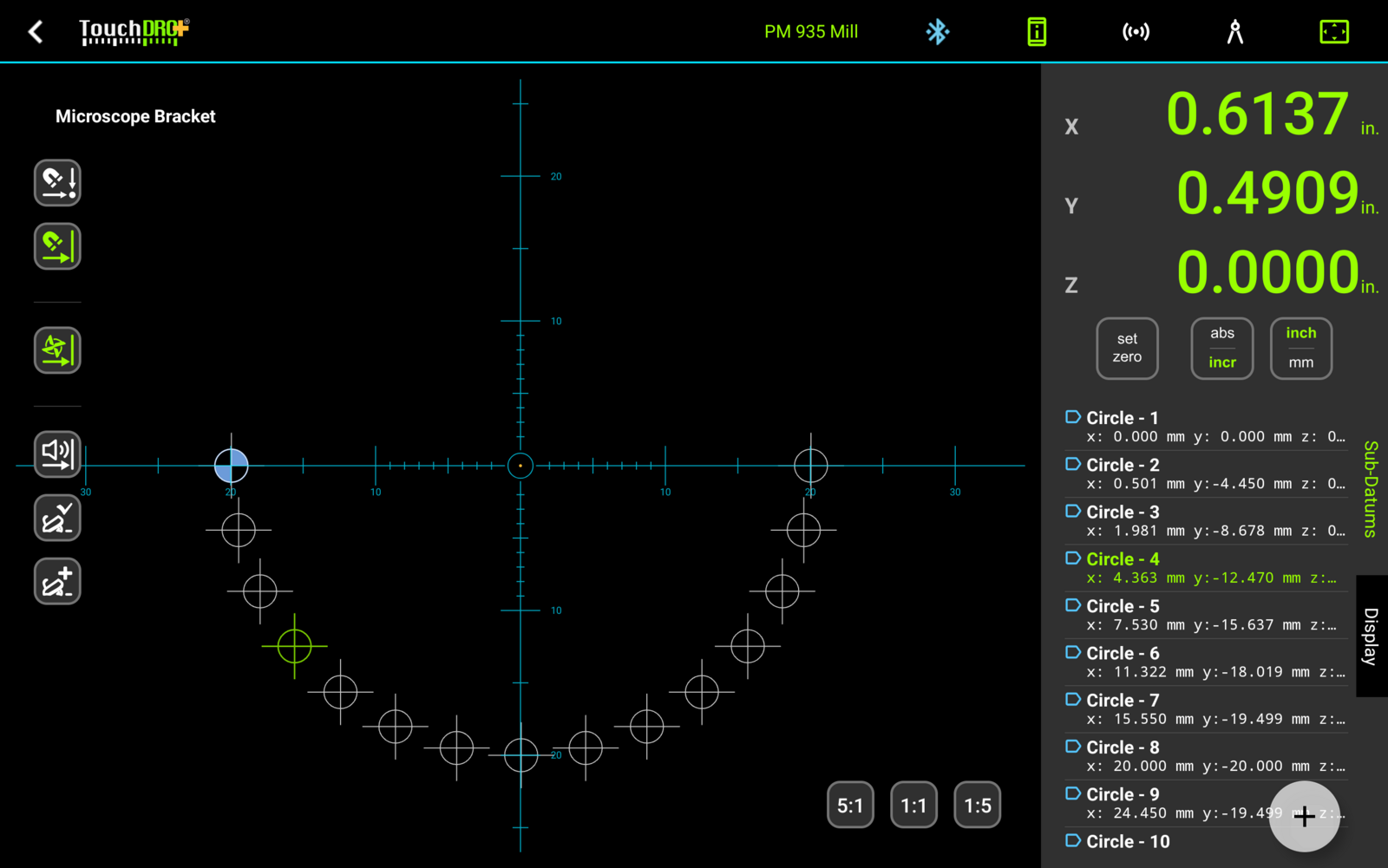
PLD (line holes, LHOLE, linear pattern, hole grid). Calculates equally spaced holes along a line at any angle, or several rows of them. With TouchDRO's "Hole Grid" function, you enter a step and a count for each direction and an angle for the whole grid, and a single row is a grid with a count of 1 in the other direction. For a row that is dimensioned by its two end holes, use the "Equidistant Hole Array" function, and to repeat a group of existing sub-datums on a grid, use the step and repeat button described in "The Sub-Datum Panel".
Arc milling (ARC, Simple R, Smooth R, arc contouring). Stepping a cutter around a radius by hand, one position at a time. With TouchDRO's "Radius/Arc Cutting" function, you enter the radius, the cutter diameter, and the stepover, and TouchDRO calculates the cutter positions for an internal or external arc in the XY, XZ, or YZ plane and stores them as sub-datums that you drive to in turn; see "Radius and Arc Cutting". You can also import a DXF drawing of the part, as described in "Machining to a CAD Drawing", which is useful for the shapes that an arc function can't describe.
Incline milling (slope, oblique line, angle function). On a console, the incline function is used in two ways: to work along a line that runs at an angle in the XY plane, and to step a cutter down a slope in the XZ or YZ plane. TouchDRO has no dedicated incline function. The closest alternatives are the "Hole Grid" function, with which you can place a row of positions along a line at any angle in any of the three planes (see "Projection Plane and Angle"), and the "Rotate Part" function, with which you can turn the stored layout to match a part that is clamped at a known angle.
Rotary table (4th axis, angular axis, dividing). With a rotary encoder on a rotary table or a dividing head, the readout can display its angle. TouchDRO has an angular axis readout that you can switch between degrees and divisions per revolution, which is useful for gears and index plates; see "Angular Axis Details". Furthermore, with the "Rotate Part" function, TouchDRO can turn the stored sub-datums and drawing together with the table, so that you keep driving X and Y to zero at every index, as described in "Rotate Part Function for Rotary Tables".
Tool Functions
Tool compensation (cutter radius compensation, tool diameter offset). Shifts the X and Y readouts by half the cutter diameter, so that the display shows the position of the cutting edge and you don't have to add or subtract the radius on every move. In TouchDRO, you enter the diameter or select a stored tool in the "Tool Compensation" dialog, and choose which side of the cutter the readout should follow. When you are milling to a guide line, TouchDRO can choose the side for you, as described under "Automatic Tool Offset".
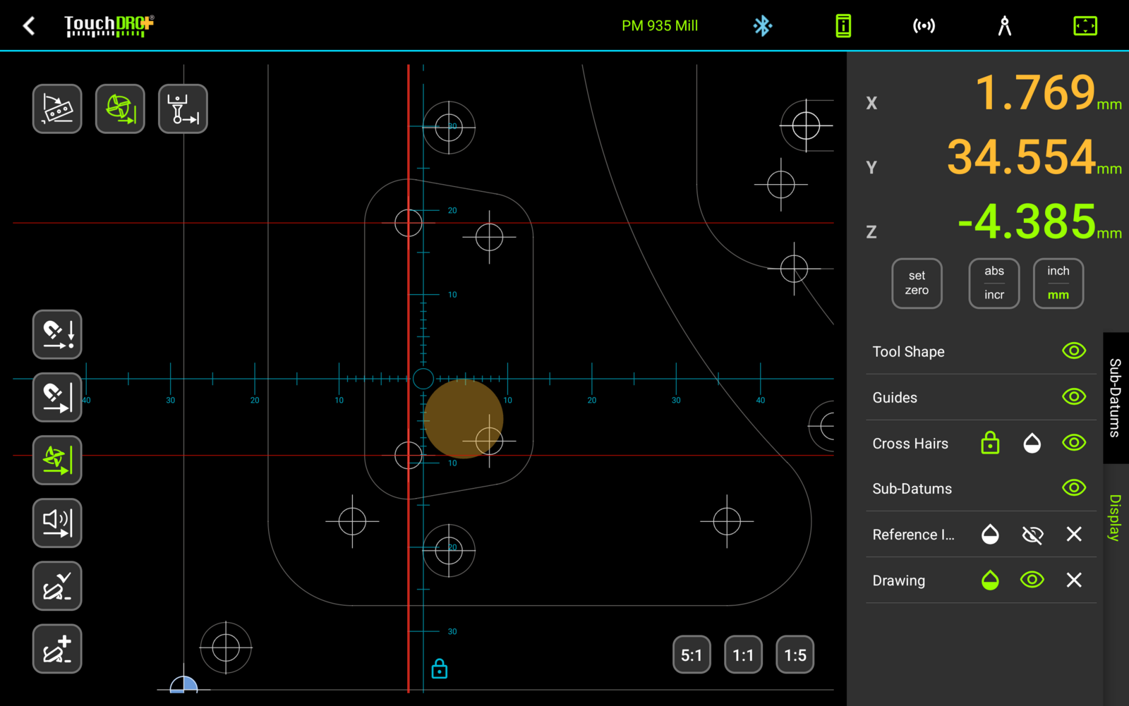
Tool table (tool library, tool memory, tool length offset). A list of stored cutters that you can recall when you change tools. In TouchDRO's tool library, covered in "Mill Tool Library and Tool Offsets", you can save the name, the diameter, the flute count, and optionally the Z offset of any number of cutters. When you recall a tool, TouchDRO uses its diameter for radius compensation and applies its Z offset to the Z readout, so with repeatable tool holders you don't need to touch off after a tool change (see "Tool Length Offsets").
Lathe Functions
The functions in this group are available when the machine profile is set up as a lathe.
Radius/Diameter (R/D). Switches the cross slide readout between the actual travel (radius) and twice the travel (diameter), so that X reads the way the drawing is dimensioned. In TouchDRO, you can switch between the two with the "Radius/Diameter" button in the function strip, covered in "DRO Function Buttons".
Lathe tool offsets (tool library, "200 tools"). Stores the position of each cutter in a quick-change tool post, so that the readout keeps its zero through a tool change. TouchDRO stores any number of tools, each with an X and a Z offset that you can set from the current position, and can draw a DXF outline of the cutter to scale in the graphical view (see "Lathe Cutter Geometry"). The basics are explained in "Lathe Tool Offset Memory Basics", the dialogs in "Managing Tool Offsets on a Lathe", and a few worked examples in "Programming Lathe Tool Offsets".
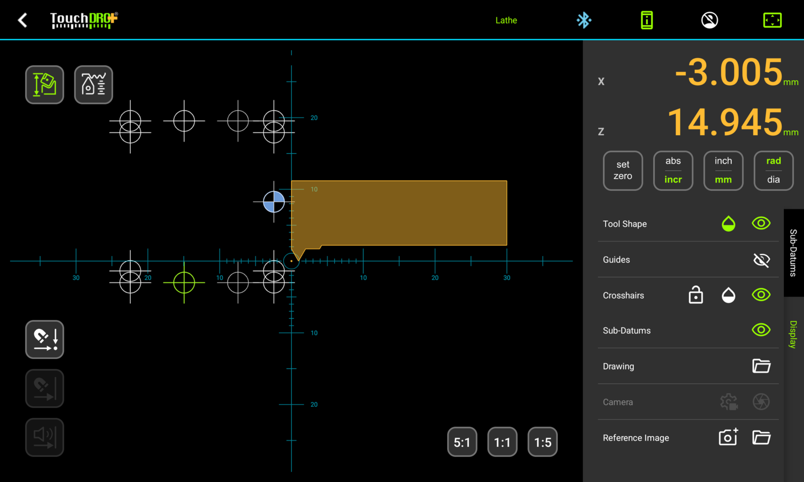
Vectoring (compound slide summing, Z+Z0). With a scale on the compound slide, vectoring splits the compound's travel into its cross slide and carriage components and adds each one to the matching readout. This way, X and Z keep tracking the tool while the compound is set over at an angle. TouchDRO's name for it is "Compound Slide Angle Compensation", and it needs the compound's scale to be set up as the auxiliary readout.
Taper measuring (taper function). Calculates the angle of a taper from the X and Z travel while you run an indicator along it. In TouchDRO, you can do this with the "Measure Distance/Angle" function: zero the axes at one end of the taper, move to the other end, and the dialog will show the distance and the angle between the two positions. On a mill, you can use the same function for the distance and angle between two features in X and Y.
Thread cutting (threading). Single-point threading on a manual lathe, where you need to keep track of the depth over a dozen or so passes. With TouchDRO's "Thread Cutting" function, you can set up an ISO metric, a Unified (UNC, UNF, or UNEF), or a custom thread, and while you cut, TouchDRO shows the depth of the last pass, the infeed, and the cut load, as described in "Thread Cutting on a Lathe". Note that TouchDRO doesn't control the lathe; it only keeps track of the numbers.
Spindle speed, surface speed, and feed rate (RPM, SFM, tachometer). With a tachometer sensor connected to the adapter, TouchDRO shows the spindle speed, and you can switch the readout to surface speed in SFM or m/min., which is calculated from the diameter you are turning on a lathe and from the diameter of the tool in use on a mill. For a machine without a sensor, you can select the speed from a list of the machine's fixed speeds or type it in, as described in "Tachometer Settings". In addition, the "Axis Details" dialog shows you the feed rate of the axis, the chip load, and on a lathe the pitch of the thread being cut.
Compensation and Accuracy
In TouchDRO, most of the settings in this group belong to the adapter input that the scale is connected to. You can find them in the "Encoder Settings" dialog, which opens from the "DRO Adapter Details" dialog.
Linear error compensation (LEC, linear compensation, scale resolution). Corrects an error that grows evenly with distance, which appears when the true resolution of a scale differs slightly from the nominal one or when the scale is mounted at a small angle to the axis. On a console, you enter the nominal resolution and then a correction factor. In TouchDRO, the two are a single number, the resolution in counts per inch, and the calibration wizard measures it against a block of known size, as described in "How to Calibrate DRO Scales".
Counting direction (scale direction, axis direction). Sets which direction of travel counts as positive, since a scale can be mounted either way around. In TouchDRO, the calibration wizard sets "Reverse counting direction" for the input automatically. To flip the sign of a single readout, you can use "Invert Readout" in the axis settings.
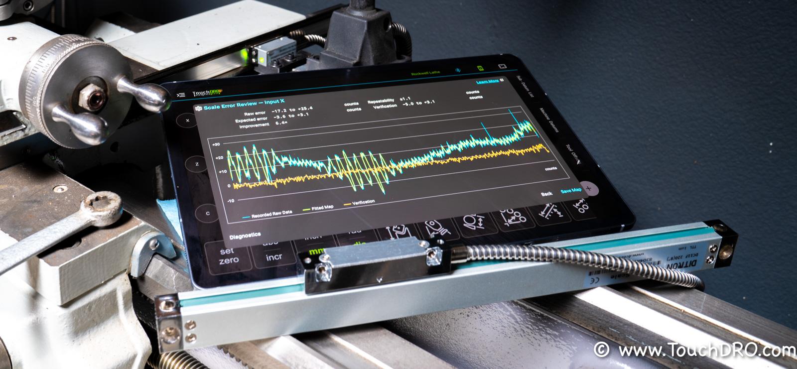
Non-linear error compensation (segmented compensation, section compensation, error mapping). Corrects an error that changes along the travel, by dividing the scale into intervals with a separate correction for each. In TouchDRO, each input can have an error map of up to 20,000 points, which you can record against a temporarily mounted reference scale or import from a file, as described in "Error Correction and Backlash Maps" and "Creating an Error Map". This is mostly useful for magnetic scales, which is covered in the "Improving Magnetic DRO Scale Accuracy" guide.
Backlash compensation. Needed when the position is measured by a rotary encoder on a leadscrew, where the screw starts turning before the table moves. In TouchDRO, you can enter one backlash value for the whole travel, or a backlash map with a separate value for each stretch of the screw, as described under "Backlash Compensation". For a linear scale, the equivalent setting is "Hysteresis".
Digital filter (vibration filter, jitter filter). On a grinder, or on any machine that vibrates, the last digit of the display flickers, and a console's digital filter steadies it by averaging the reading. TouchDRO has no setting that averages the display. Note that the "Input filter" switch in the encoder settings is intended for home-built adapters whose raw signal needs conditioning, so leave it off with a current TouchDRO adapter.
Reference marks (REF, RI, reference zero). Many glass and magnetic scales have one or more reference marks, which give the readout a repeatable position to return to after the power has been off. With a TouchDRO adapter that supports scale referencing, you can run the "reference-mark routine" from the "DRO Adapter Details" dialog: move the axis toward the mark, and the adapter will set its counter to zero there. As a result, you get the same machine zero after every power cycle.
Head angle compensation (tilted or nodded head). When the head of a milling machine is tilted or nodded over, part of every quill movement is along X or Y, and a readout that simply adds the quill to the knee drifts away from the true cutter position. With TouchDRO's "Head Angle Compensation" function, you enter the tilt and nod angles of the head, and TouchDRO splits the quill travel into its components and adds each one to the matching readout.
Probing and Measuring
Edge finder (electronic edge finder, touch probe, center find). Sets the zero on an edge, a centerline, or the center of a bore, with the radius of the edge finder's tip taken into account. TouchDRO's "Indicate Workpiece" function provides a way to do this with a manual edge finder, a camera, or a touch probe wired to the adapter's probe input, in which case TouchDRO can register the touch automatically; see "Edge Finder (Indicate Workpiece) Function". The tip diameter and the offsets of each instrument are stored in a probe profile, covered in "Probe Profiles" and in the "Touch Probe Setup and Calibration" guide.
Tool setter (Z reference, tool height setter). Sets the Z zero by touching the cutter off on a surface of known height. With TouchDRO's "Set Z Reference" function, you select the instrument and enter the Z value that the surface should read, and TouchDRO adds the height of the setter for you. With an electronic tool height setter wired to the adapter, TouchDRO can also detect the touch, as described in the "How to Use a Tool Height Setter" guide.
Measuring functions (2D measurement, inspection). Calculating a distance, an angle, or a circle from points that you locate on the part, which among consoles is mostly found on the metrology readouts made for optical comparators. On a mill, TouchDRO's "measurement mode" has seven measuring functions: "Point", "Point-to-Point Distance", "Circle from Points", "Line Angle", "Angle Between Lines", "Distance Between Lines", and "Outline from Points". You can save the results as sub-datums or send them to an inspection log, as described in "Measurement Functions".
Skew compensation (part alignment). Used to measure a part that isn't clamped square to the table, by aligning the axes of the readout to an edge of the part. In TouchDRO's measurement mode, you can do this with the "Align Measurement Axes" function, with the angle typed in, read from an encoder, or measured from two points on the edge. For machining, you can turn the stored sub-datums and drawing to match the part with the "Rotate Part" function.
Polar coordinates (distance and angle display). Shows a position as a distance and an angle from the origin, in place of X and Y. TouchDRO has no polar mode for the readouts. The "Measure Distance/Angle" dialog shows you both numbers live for the current position, so you can leave it open and move the table until the distance or the angle reads what the drawing calls for.
Video edge finder (camera, microscope, optical center finder). Locates a feature by eye under a crosshair, which is useful for features that a probe can't touch, such as a scribed line, a punch mark, or a hole smaller than the probe tip. TouchDRO can show live video from a USB microscope or camera in the graphical view, with the crosshairs over the image, and you can use the camera as the instrument for indicating a workpiece and in measurement mode, as described in "Live Camera Feed".
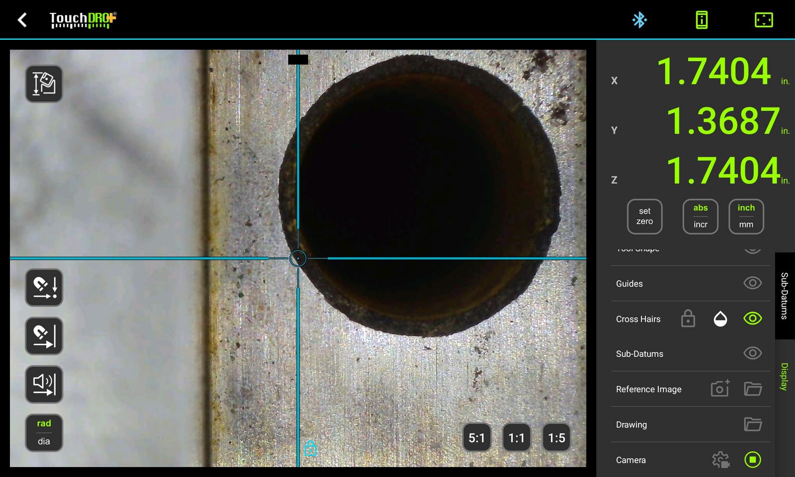
Gauge input (digital caliper, micrometer). Reading a hand-held measuring instrument on the readout's own display. With TouchDRO's "Measure Dimension" function on a lathe, you can see a caliper or micrometer that is wired into the adapter as a full-size readout, and copy the measurement into the X axis as a diameter.
Data and Connectivity
RS-232 output (data output, serial port). Sends the readings to a computer, a printer, or SPC software. TouchDRO has no serial port. With "Live Data Streaming", you can send the positions over the network as a TCP server or an MQTT client, in delimited text or JSON, at a fixed interval or when a value changes, and there is a worked example in the "Monitoring a Manual Mill with MQTT" guide.
CAD import (DXF import, drawing display). Showing the drawing of the part on the readout itself, at true scale, with the spindle position on top of it. In TouchDRO, you can import a DXF file from any CAD program into the graphical view and extract its hole centers as sub-datums, as described in "CAD Drawing Import". For work that doesn't need tight tolerances, you can use a photo of the part in a similar way; see "Reference Image Overlay".
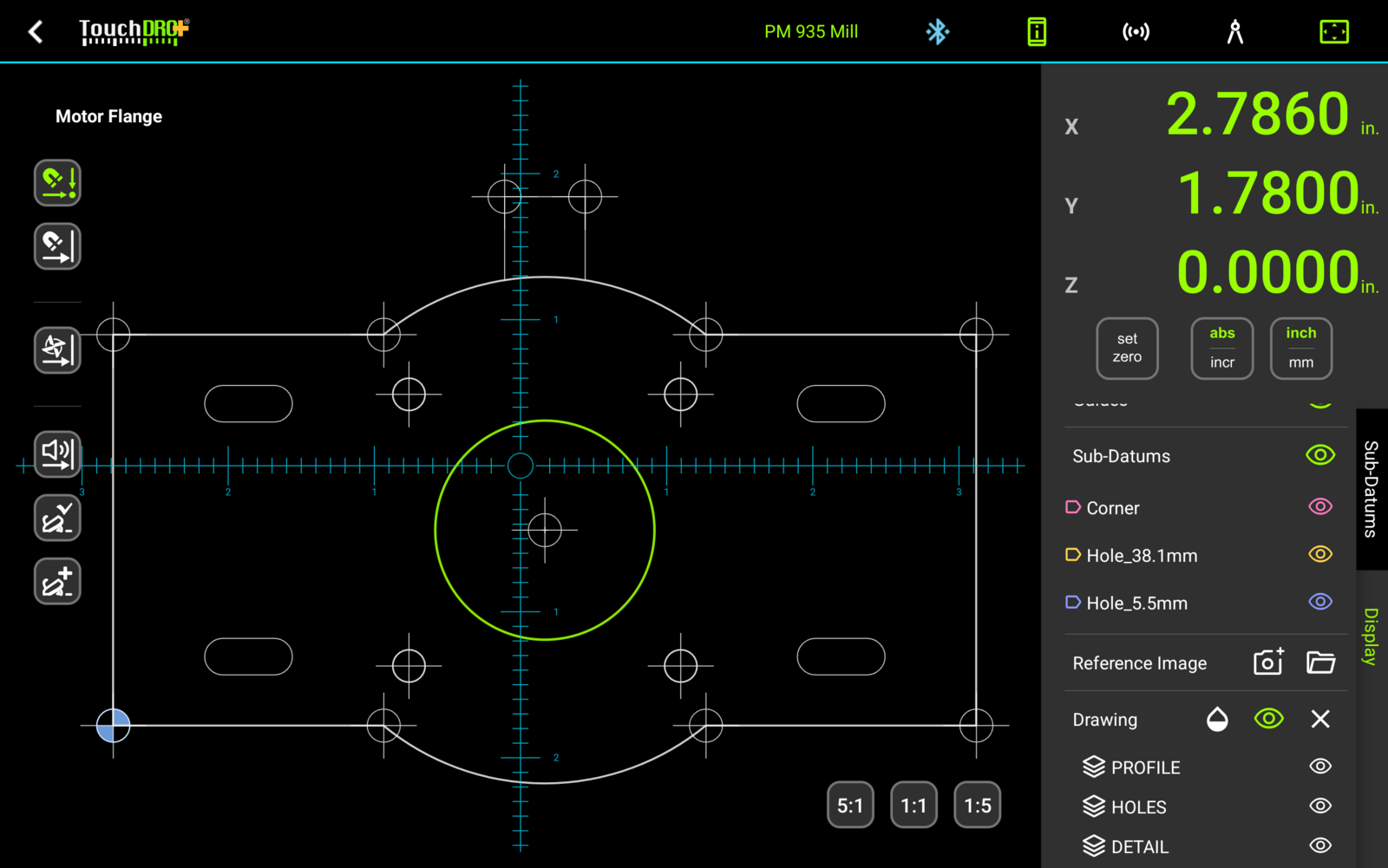
Coordinate import and export (CSV, DXF export). Moving stored positions between the readout and a computer. In TouchDRO, you can import sub-datums from a CSV file prepared in a spreadsheet and export them the same way, as described in "Importing and Exporting Sub-Datum Coordinates". You can also export the whole workspace as a DXF file, with the sub-datums, the guides, and the drawing geometry in it and the tags as layers; see "Exporting a Workspace to DXF".
Wireless connection (Bluetooth, USB, WiFi). On a console, the scales plug into the back of the display. In TouchDRO, the scales plug into an adapter mounted on the machine, and the tablet connects to it over Bluetooth, so there is no cable between the machine and the display, while USB and WiFi connections are available for home-built adapters. See "Connecting To TouchDRO Scale Adapter" and, for the tablet, "System Requirements".
Firmware update (software update). New functions and fixes for the hardware after you have bought it. You can update the firmware of a TouchDRO adapter from the application, with the tablet you already use. TouchDRO downloads the firmware and installs it over a USB cable, or over Bluetooth if your adapter supports it, as described in "Updating the Adapter Firmware".
Convenience Functions
Calculator. A console's built-in calculator provides a way to do the arithmetic at the machine and transfer the result to an axis. TouchDRO has no separate calculator screen. The numeric fields accept arithmetic, so you can type "1/2+0.015" into the "Set Dimension" dialog, or "3.75/2" for the radius of a 3.75" bolt circle, right where the number is needed.
Near-zero warning (zero approach). Signals that an axis is getting close to zero, so that you can keep your eyes on the cut. In TouchDRO, the warning is audible: the beeps start 0.100" (2.5 mm) from zero, get faster as you approach, and turn into a solid tone within 0.005" (0.13 mm). Note that the warning can be active for one axis at a time, as described under "Near-Zero Warning".
Graphical display (graphic positioning aid). Newer LCD consoles can draw a hole pattern, or the distance left to zero, as a simple graphic. In TouchDRO's graphical view, you can see the whole workspace as a drawing to scale, with the sub-datums, guides, imported drawing, and cutter in their true positions and the crosshairs following the spindle; see "Graphical View Display".
Power-off memory (position retention). A console saves the position when it is switched off and restores it when it comes back on. In TouchDRO, the adapter does the counting, and as long as it has power, it keeps track of the position whether or not the tablet is on or connected, as explained under "Scale Interface Adapter". The TDA adapters also save the position when they lose power, although, as with any incremental scale, a movement made while the power is off isn't counted.
Sleep mode. Blanks the console's display while the scales are still being counted. TouchDRO has no sleep setting, and it keeps the screen on while the application is open. To get the same result, you can turn the tablet's screen off or close the application, since the adapter keeps counting without it.
Machine type (mill, lathe, grinder, EDM). A universal console is switched between its mill, lathe, grinder, and EDM modes in the setup menu. In TouchDRO, you create a machine profile for each machine, as described in "Machine Profiles", with "Vertical Mill", "Horizontal Mill", or "Lathe" as the machine type, and one tablet can serve several machines, each with its own settings, workspaces, and tools. There is no grinder or EDM machine type.
EDM depth control. On an EDM console, the readout switches a relay when the ram reaches the set depth, which stops the burn. TouchDRO has no EDM function, and it doesn't switch anything when an axis reaches a target, so it can't replace an EDM readout.