Linear (X,Y,Z) and Angular Axis Settings
TouchDRO can display up to five readouts on the main screen:
- Three linear axis readouts (X, Y, and Z) that represent a tool position within a standard Cartesian coordinate system. Each readout can be configured to receive position from any one scale, or sum-up positions from two scales
- One angular axis readout "α" that can display the angle of a rotary table or an indexing head. The readout can be configured to receive position from any one scale input.
- Tachometer readout that can display spindle rotations per minute (RPM) or cutting speed. Tachometer is hard-coded to display data from the "t" input.
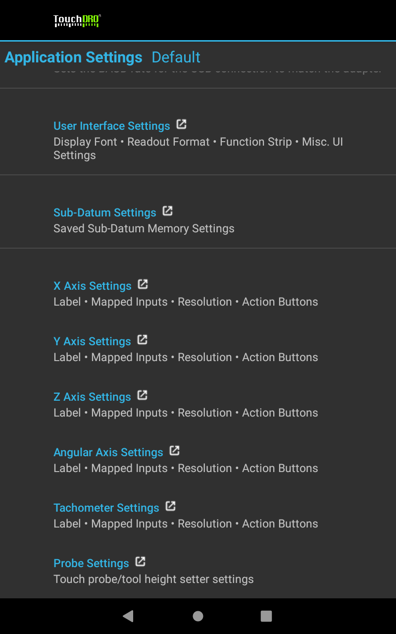
Each axis readout can be enabled/disabled and configured individually to suit particular machine configuration and user preferences.
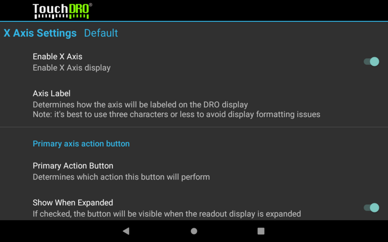
Enable Axis
Determines whether or not the axis output is enabled to suit a particular machine setup. For example, when used with a vertical milling machine, all three linear axes might be shown, while a surface grinder would likely not use the X axis; a lathe won't need Y axis readout.
Note 1: At least one axis must be enabled. As a result, TouchDRO will prevent the last enabled axis to be disabled and will show a warning stating so
Note 2: For the graphical view to work at least two linear axis outputs must be enabled; otherwise, the application will display a bank screen instead of the 2-dimensional workspace representation.
Axis Label
Label that will be shown next to each axis readout on the main screen. The application accepts labels that are 1-3 characters long.
Note: This setting will be deprecated in the future, so it's best to use the standard X,Y, and Z labels.
Axis Button Settings
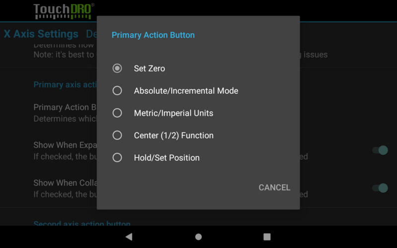
Each linear axis can have up to three action buttons that appear on the main readout screen. The action that each of the three buttons will perform and whether or not it will be displayed when the side panel is visible or hidden can be configured using their respective [identical] configuration sections.
By default, the first button is configured to show "Set Zero" action and be shown when expanded and collapsed. The other two buttons are set to toggle between Absolute and Incremental coordinate systems and Inches and Millimeters respectively. Second and third buttons are configured to be shown in expanded mode, but for some wider screens, there might be enough space to show one or both of them in collapsed mode as well.
Button Action
Determines which action the button will perform when clicked.
Show When Expanded
When checked, the button will be visible when the readout display is expanded (i.e. the right panel is hidden)
Show When Collapsed
When checked, the button will be visible when the readout display is collapsed (i.e. the right panel is visible)
Input Settings
An input is a stream of data received from the TouchDRO adapter for a particular scale and consists of the input prefix (different from axis label) and the number that represents encoder steps. Each axis readout can receive position data from one or two inputs. By default each axis is configured to receive data from one input but when desired, a second input can be enabled, so the readout can combine readings from two scales (for example Z axis on a knee mill could combine input from a scale mounted to the knee and the quill).
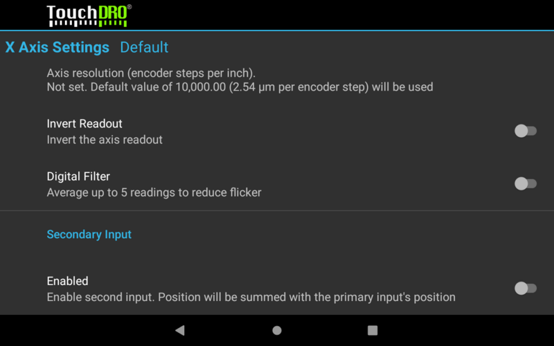
Enabled (Secondary Input Only)
Determines whether the secondary input will be used. When checked, the section will show settings similar to the primary input
Prefix
Determines which input stream should be used for this input. By default X, Y, Z, and Angular axis redouts are set to receive "x", "y", "z" and "w" inputs respectively.
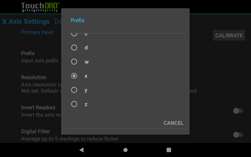
Note: Even though current TouchDRO adapters output only x,y,z, and w streams, the application includes options for a,b,c, and d prefixes. This is done for future expandability or can be utilized by using a DIY adapter that runs a custom Arduino sketch.
Resolution
Determines the count of encoder steps per 1 inch of travel (CPI). The default is set to 10000 coups per inch and needs to be set to match the scales used in the given setup.
CPI can be set directly by editing this setting or by using the calibration process. Some common DRO scale resolutions are as follows:
- 5-micron glass and magnetic scales - 5080
- 1-micron glass and magnetic scales - 25400
- iGaging EZ-View and DigiMag scales - 2650
- Other capacitive scales - 2540
Invert Readout
When checked, the axis input will be inverted to account for scenarios where the scale has to be mounted backwards.
The setting can be toggled directly or set via the calibration process.
Digital Filter
When enabled, the application will use a weighted average of up to five readings to remove jitter caused by iGaging EZ-View and DigiMag scales.
