TouchDRO TDA-400/420 Adapter Manual
TouchDRO TDA-400 and TDA-420 are the latest generation of our scale interface adapters designed for use with the majority of modern optical and magnetic DRO scales. Thanks to the powerful 32-bit dual core processor and state-of-the art software, these adapters offer unparalleled performance and capabilities that can't be found in any other DRO unit on the market.

TDA-400
TouchDRO TDA-400 is a four-axis DRO scale adapter, designed to work with most modern optical and magnetic DRO scales.
- Up to four 5V RS-422 (differential) or TTL (single ended) DRO scales or rotary encoders (NPN, PNP, and Push-Pull) with reference track support.
- Bluetooth and USB connectivity (can be used simultaneously)
- Position retention during power loss
- Access to TouchDRO Plus application
- Support for over-the-air firmware update
TDA-420
TouchDRO TDA-420 is an enhanced version of the TDA-400 adapter. It includes all of the features listed above, and adds two additional flexible TTL inputs that can be configured for a few different use cases.

What is Included
When you receive your TDA scale adapter, it will be ready to go:
- TDA-400 package includes the adapter module, a USB A male to USB-C male cable, and a quick start card.
- TDA-420 package includes the adapter module, a USB A male to USB-C male cable, two Mini-DIN 4 male connectors, and a quick start card.
Features
Four RS-422/TTL Scale Inputs
Both adapters come with four scale inputs that support 5 Volt RS-422 and TTL quadrature encoders. This includes the vast majority of modern DRO scales (optical, magnetic and inductive) and NPN, PNP, and Push/Pull incremental rotary encoders.
TTL scales (also called single-ended) use two lines, A and B, to send the position data to the DRO. Many DRO scales also include a reference line, often labeled R or Z, that outputs a pulse at a predefined distance (more on this later).
RS-422 inputs (also called differential) use a complementary pair for each line. The additional lines are often marked as A'/B', A-/B-, etc. Those lines carry inverted signals, so when line A is high, line A' is low, and vice versa. When the two inputs are combined by a special differential driver circuit, the noise is canceled.
Support for Reference Track
The four primary scale inputs include support for a reference track. Good quality DRO scales usually come with a reference track with reference marks spaced at predefined distance, or a single "home" mark, usually in the middle of the scale. Since reference marks are usually very precise, they can be used in TouchDRO to restore the machine's coordinate system to a known position.
Auxiliary TTL Inputs
TouchDRO TDA-420 adapter comes with two additional flexible TTL lines that can be used for a combination of the following:
- Two TTL quadrature encoder inputs. These inputs can handle combined quadrature signal frequency of up to 100KHz and support NPN or Push/Pull encoder input (this includes virtually all quadrature DRO scales)
- Two touch probe or tool height setter inputs on Aux. line #1
- Tachometer input on Aux. line #2
- Two pairs of home switch inputs. Home switches can be used to zero out a specific primary axis (X, Y, Z, or W) when the input line is pulled low (shorted to the ground).
Position Retention on Power Loss
Both TDA adapters are equipped with non-volatile memory (EEPROM) and a power loss detection circuit that records the last known scales position when the adapter is powered down. When the power is restored, the adapter will check the data integrity, verify that the scales were not in motion, and restore the positions. If the checks fail, it will send an error message to the application alerting the machinist of the potential position loss.
BlueTooth and USB Connectivity
TouchDRO TDA adapters come with a BlueTooth 4.2 transceiver and a high speed USB bridge. The firmware can use either BlueTooth or USB to send the data, or both connection modes can be used simultaneously. For example, BlueTooth can be used to connect to a tablet and USB can be plugged into a computer for real-time data capture.
Support of Over-the-Air Updates
The software running on the TouchDRO adapters (also called firmware) will continue to be updated and receive additional functionality. This firmware can now be updated directly from the TouchDRO application. When a new firmware is released, the app will ask if you want to update the firmware. If the update is approved, the code will be uploaded to the microcontroller.
Access to TouchDRO Plus Application
TouchDRO Plus adds a number of advanced features that are not available with the free version of the application. The TDA adapters include the activation license for the Plus features. When you first connect to the adapter, TouchDRO application will detect the activation license, verify it against the activation server and turn on the features.
Main Input Pinout Options
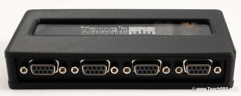
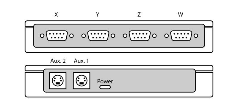
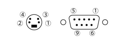
Four main scale inputs on TouchDRO TDA-400 and TDA-420 use female DB-9 (D-Sub 9) connectors preconfigured for one of the scale peanuts listed in the table below.
| Brand | 1 | 2 | 3 | 4 | 5 | 6 | 7 | 8 | 9 |
|---|---|---|---|---|---|---|---|---|---|
| Acu-Rite SENC Scales | A | A' | B | B' | OV/Gnd | Vcc/5V | R | R' | |
| Electronica/EMS, PM MagExact | +Z | Z' | Vcc/5V | Shield | OV/Gnd | A | A' | B' | B |
| Ditron, Sino, Aikron, Easson, Vevor | A' | 0V | B' | Shield | R'/Z' | A | +5V | B | R/Z |
| Generic Chinese Pinout (ToAuto, etc.) | 5V | 0V | A | B |
For more detailed information plese refer to Supported Optical and Magnetic DRO Scales
Auxiliary Inputs
By default, Aux. 1 input is configured for two touch probe inputs, and Aux. 2 is configured for tachometer input. The table below shows all possible input configurations.
| Pin 1 | Pin 2 | Pin 3 | Pin 4 | Note | |
|---|---|---|---|---|---|
| Touch Probe | Gnd. | 5V | "q" signal | "p" signal | Aux. 1 only |
| Tachometer | Gnd. | 5V | "t" | --- | Aux. 2 only |
| Quadrature | Gnd. | 5V | A | B | Aux. 1 - "u", Aux. 2 - "v" |
| Limit switch X/Y | Gnd. | 5V | X | Y | |
| Limit switch Z/W | Gnd. | 5V | Z | W | |
| Serial data | Gnd. | 5V | Clock | Data |
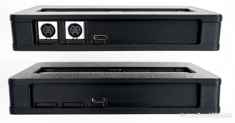
Port Layout and Pin Functions


Touch Probe Wiring
The TDA-420 scale adapter supports up to two triggering touch probe inputs. Touch probe inputs are mapped to "p" and "q" axis labels (configurable on the Touch Probe Settings page). The inputs support normally-open and normally-closed touch probes and tool setters. Note that input type is automatically detected during adapter boot time. Therefore, the probe must be plugged in and not triggered when the adapter is powered up, or the probe will not function correctly.
Digital touch probes can use a two or three-wire connection scheme. Most passive probes use two wires; active probes, and probes with multi-color LEDs use three wires.
Three-Wire Probes
Three-wire probes have internal components used for signal conditioning and/or driving two-color LEDs. The three leads are Vcc, Ground, and Signal leads and should be connected to 5V, Ground, and "p" (or "q") inputs respectively.
Two-Wire Probes
Two wire probes usually behave like a basic electrical switch:
- Conductive probes and tool setters are normally-open. When the stylus touches the workpiece (or the cutter touches the tool setter surface), the circuit is closed through the machine's body.
- Non-conductive kinematic probes are normally closed. When the stylus is deflected by touching the workpiece, the connection is broken.
To connect the probe to TouchDRO, solder one of the probe's leads to the Ground pin and the other to "p" or "q" input:
- For the touch probes without LED, the orientation does not matter.
- Touch probes with LEDs that are designed for a 5V system will work with the pins wired in either orientation. To retain the LED function, refer to your touch probes documentation to determine which wire is connected to 5V.
- Touch probes with LEDs that are designed for operation voltage higher than 5V might not work when the LED is forward biased. Such probes need to be wired "backward" to reverse-bias the LED (and effectively take it out of the circuit).
Technical Characteristics
Position Refresh Rate
The adapters send the scale position to the application every 40 milliseconds (25 times per second) when active, and once per second when idle.
Quadrature Signal Frequency
The maximum recommended quadrature signal frequency is 1 MHz. This is equivalent to a 1 micron scale moving at 4 meters per second, or a 5 micron scale moving 20 meters per second. The absolute maximum frequency is a bit under 4 MHz.
The two auxiliary inputs (TDA-420 only) can reliably handle combined quadrature signal frequency of 100 KHz. In other words, if both axes are moving, their combined signal frequency should not exceed 100KHz; when a single axis is moving, it can output a full 100KHz. This is equivalent to a 1-micron scale moving at 0.4 meters per second, which is on-par with most modern DRO units.
Reference, Touch Probe, and Home Switch Latency
When the reference lines, touch probe, and home switch line signal changes form on to off stage, the adapter must respond to the event and perform the appropriate action. This takes some amount of time. The TDA adapters can handle the interrupt in about 2 microseconds or less. This translates to some amount of repeatability error. For example, a home switch is triggered when a 1-micron scale is moving at 1 meter/second, the error will be 8 encoder steps, or 8 microns. At a more reasonable speed, the error will be well under one encoder step.
Tachometer Signal Frequency
The adapters have a low limit of 0.5Hz and upper limit of 100 KHz input frequency for the tachometer. In other words, the adapter will count pulses that are at most 2 seconds apart, and up to 1/100000 of a second. In terms of RPM, this translated to 30 RPM minimum and 6 million RPM maximum with a single-slit tachometer disk, or 3 RPM to 600,000 RPM with a ten-slit disk. The measurement error is under 1%.
Minimum/Maximum Ratings
| Nominal | Minimum | Maximum | |
|---|---|---|---|
| Supply Voltage | 5 V | 4.0 V | 5.5 V |
| Current Draw | 15 0ma | 50 ma | 300 ma |
| Primary Scale Inputs | |||
| Signal Frequency | 1 MHz | --- | 4 MHz |
| Min Edge Separation | 250 ns | 250 ns | --- |
| Reference Trigger Latency | 2 µs | 2 µs | 2 µs |
| Signal High Level | 5 V | 2 V | 5.5 V |
| Signal Low Level | 0 V | -0.3 V | 0.8 V |
| Auxiliary Inputs | |||
| Quadrature Signal Frequency | 50 KHz | --- | 100 KHz |
| Min. Edge Separation | 5 µs | 5 µs | --- |
| Probe/Home Switch Latency | 2 µs | 2 µs | --- |
| Tachometer Signal Frequency | 100 KHz | 0.5 Hz | 100 KHz |
| Signal High Level | 5 V | 2 V | 5.5 V |
| Signal Low Level | 0 V | 0 V | 1.1 V |
