How to Find the Pinout of an Unknown DRO Scale

We often get questions from people trying to figure out if their mystery DRO scales will work with TouchDRO. These scales usually turn out to be rebranded units from one of the Chinese DRO manufacturers — or, in the case of some older scales, from their Taiwanese and Hong Kong predecessors. In most cases the scale will work, as long as it outputs 5V TTL quadrature. The main question is whether the scale can be identified well enough to determine its output type and pin functions.
If you know the scale brand or the DRO display model, start with the DRO Scale Compatibility page — many common scale brands are already covered there. If the scale is from an obscure brand or has no markings at all, it's usually a rebadged Chinese unit, and most Chinese scales use one of two common DB-9 pinouts that you can tell apart just by opening the connector shell and checking which pins are wired.
If the connector doesn't match either pattern but the original DRO display is still working, we walk through how to reverse-engineer the pinout from that display. If the display is dead or missing, things get trickier, but you can often still identify the scale from the output driver IC inside the reader head.
Chinese Scales
If your scale looks similar to the one in the photo below, and comes with a 9-pin D-Sub connector, it's likely a rebranded DRO scale from one of the major Chinese manufacturers. Virtually all Chinese scales use one of two pinout schemes.

You can usually determine which your scale uses by opening the connector and checking which pins have wires soldered to them. Depending on whether the scale outputs a single-ended or differential signal, and whether it has a reference signal, you might see four, five, six, or eight wires — four or five are the most common.
Why DRO Wire Color Codes Aren't Reliable
The first shortcut people try is to identify pin functions by wire color — red for Vcc, black for ground, and so on. It doesn't work. There's no industry-standard color code for DRO scale wiring, and even two scales with identical internals can ship with completely different colors depending on the production batch or the cable supplier. Always identify pins by their position in the connector, not by the color of the wire soldered to them.
The Two Common Chinese Pinouts
The more common of the two pinouts was originally introduced by Ditron, and is now used by Sino, Easson, Aikron, M-DRO, and many other brands. The less common pinout is used by ToAuto, older Precision Matthews scales, and some house-brand DROs.
If you see four or five wires connected to the first row (pins 1–4 or 1–5), as shown below, your scale almost certainly uses the less common pinout.
")
If you know you have a Chinese scale and it doesn't match that pattern, you likely have a Ditron-compatible scale. There are a few different things you might find inside the connector:
Single-ended scales are most common, and will have pins 2, 6, 7, and 8 connected, possibly pin 9 if the scale has a reference pulse output.

Differential scales can be a bit more complicated. Usually you'll find all 9 pins wired to something, with pin 4 possibly carrying the cable shield. One gotcha: Electronica/EMS scales use a visually identical pattern (8 signal wires plus shield on pin 4) even though the actual pin assignments differ from differential Ditron scales.

Mystery Scale
If you can't figure out the pinout by looking at the connector, the next step is to reverse-engineer it. The goal is to identify the power and ground pins first, and then use an oscilloscope to map the signal and reference lines. How you find power depends on what you have to work with — if the original DRO still powers the scale, you can probe the connector directly; if not, you'll need to open up the scale and trace the lines from the internal circuit.
A basic handheld single-channel oscilloscope is more than enough — the one we'll use below was $34 on Amazon.

Finding Power and Ground
The first step is to find the power supply lines. How you do this depends on whether you still have the original DRO display.
You Still Have the Original Display
The DRO doesn't need to be fully functional — a cracked display, missing buttons, or stuck error codes are all fine, as long as it still provides power to the scale.
Set the vertical scale on the oscilloscope to 2 Volts per division, and the horizontal scale to 1 ms per division. Attach the alligator clip to one of the wires and the probe to any other wire, then move the scale slowly and watch the oscilloscope screen. You'll see one of a few different things happen:
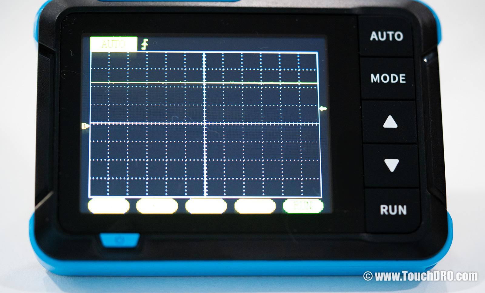
- If the line stays almost flat around 5V (as shown above) as you move the scale, you've found the power supply pair.
- If the line stays flat at some voltage below 0V, you likely have the alligator clip and the probe reversed — swap them and try again.
- If the line jumps off the screen when you connect the probe, change the vertical resolution to 2V per division.
Once you find the pair of pins where the line stays close to flat, mark the pin with the alligator clip as "ground" and the one with the probe as "Vcc". Count the number of divisions to determine the supply voltage. For most modern scales it will be close to 5V; if you find that your supply is much higher than 5V (12V or 24V, for example), your scale is not compatible with TouchDRO, unfortunately.
No Original Display, or It's Dead
If you don't have access to the original DRO display, or it's completely dead, you might still be able to figure out the wiring by tracing the lines from the scale's internal circuit.
Most glass DRO scales use an output circuit built around one of a handful of common ICs. Single-ended TTL scales almost always use the ubiquitous LM339 comparator. Differential RS-422 scales typically use one of the AM26xx31-family line drivers — the AM26LS31 and AM26C31 (5 V), the AM26LV31 (3.3 V), or pin-compatible parts like the DS26LS31 and ST26C31B. If the markings on top of the IC are still legible and you recognize one of these parts, tracing the supply lines is straightforward.

Orient the IC so the notch faces up or the beveled edge faces left — pin 1 (sometimes marked with a small dot in the corner) is in the upper-left, with the rest counting counterclockwise. On the LM339, pin 3 (third pin down on the left) is Vcc and pin 12 (third pin from the top on the right) is ground. On the differential drivers, pin 16 (upper-right corner) is Vcc and pin 8 (lower-left corner) is ground.
With the supply pins identified on the IC, use a multimeter in continuity mode (with the scale unpowered) to find which connector wires trace back to them.
If the IC is marked but you don't recognize it, search for the part number online and pull the pinout from the datasheet. If the markings have been ground or etched off, look for electrolytic capacitors on the board — the positive lead usually goes to Vcc and the negative lead to ground.
Some scales have potted electronics that aren't accessible at all. In that case the only option is to gamble with a current-limited bench power supply, which can be destructive, so we won't cover it here.
Once you know which connector pins carry power and ground, you can power the scale up and use the oscilloscope method below to map the signal and reference lines.
If you identified one of the common ICs above, you've essentially confirmed the scale will work with TouchDRO, so the simplest option is to wait until your adapter arrives and use it as the power source — it supplies 5V on the scale connector, so plugging the scale in does the job. In a pinch, a USB phone charger with the cable cut open works too. Either way, double-check polarity before connecting — swapping Vcc and ground is the fastest way to smoke the scale.
Finding the Signal Pins
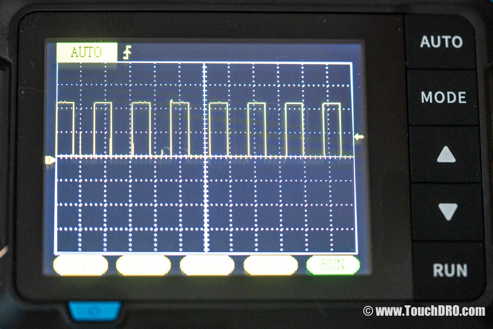
Now that you have the ground pin figured out, we can find the signal lines.
Attach the alligator clip to the ground and probe each of the other pins in turn. As you move the scale, you'll see one of the following behaviors:
- A fast-switching square wave that goes between 0V and 5V — mark this pin as a quadrature signal.
- A sinusoidal signal with smaller amplitude (for example, 1V riding on a ~4V DC offset, or 2V peak-to-peak centered somewhere in the middle of the supply range) — mark this pin as an analog signal.
- A brief pulse every few inches, or just in the middle of the scale — mark this pin as a reference.
Once you've probed all of the connected pins, you should have two or four signal pins, and zero, one, or two reference pins (not all scales have reference pins).
If you have two quadrature signal pins, you're done — you have a single-ended scale (with a reference track if you also found a reference pin).
Identifying Differential Pairs
If you have four signal lines, it means that your scale outputs a differential signal, so we now need to find the differential pairs.
Attach the alligator clip to one of the signal lines, and the probe to any other signal line. Move the scale slowly and see what happens to the oscilloscope trace. You'll see one of two behaviors:
- A square-wave signal switching between two levels, potentially with a small glitch at the start and/or the end (shown below) — you've found a pair.
- A trace that sits at three levels (roughly 5V, 0V, and −5V), or a messy, unstable pattern (shown below) — move the probe to a different pin and try again.
A pin from a different pair, by contrast, gives you a three-level pattern:
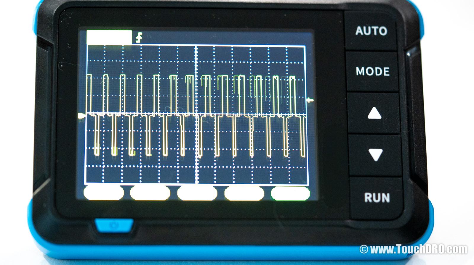
Once you find one of the differential pairs, mark the pins A and A'. Mark the two other signal pins as B and B'. If your scale has two reference pins, mark them as R and R'.
Connecting to TouchDRO
At this point you should know which connector pins carry Vcc and ground, which carry the A and B quadrature signals, and which (if any) carry the reference pulse or the differential complements.
You don't need to know which line is A and which is B. If you swap them the scale will read backwards — that's easily corrected in the TouchDRO application settings.
Take a look at the Main Input Pinout Options in the TDA-410/420 adapter manual. If your scale matches one of the listed pinouts, you can order the adapter pre-pinned for your scale. Otherwise, you'll need to re-pin the connector or build a pigtail cable to match one of the supported pinouts.