TouchDRO Initial Configuration
TouchDRO offers a lot of flexibility and can be customized for a variety of use cases. When you start the application for the first time, it will load the default settings that might be incorrect for your particular machine setup. Therefore, before using TouchDRO, it will be necessary to correctly configure the application. The configuration is done using the TouchDRO Settings page that can be accessed from the main application drawer menu.
In this guide, we will cover only the settings that need to be configured for the application to work correctly; for additional information about TouchDRO configuration and features, please refer to the User Manual.
If you are planning to use TouchDRO with multiple machines or on a combination machine (such as mill/lathe combo or a horizontal/vertical mill), start by familiarizing yourself with the concept of TouchDRO Configurations.
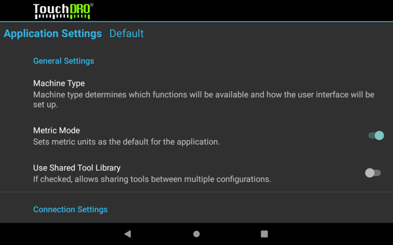
General Settings

Machine type determines which functions are enabled, the format of the saved tool offset library, and the default projection in the graphical view and sub-datum memory.
When Metric Mode is enabled, TouchDRO will default to metric units throughout the application, including the sub-datum memory, some settings, etc.
Use Shared Tool Library setting should be enabled if you are upgrading from TouchDRO V2.5; for new installation it's recommended to leave it off.
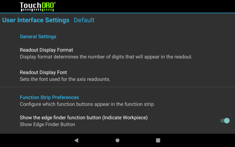
User Interface Settings

Readout Display Format determines how many digits will be displayed after the decimal point. For glass and magnetic DRO scales 0.0000 in/0.000mm is recommended; for capacitive scales 0.000 in./0.00mm might provide a more stable display.
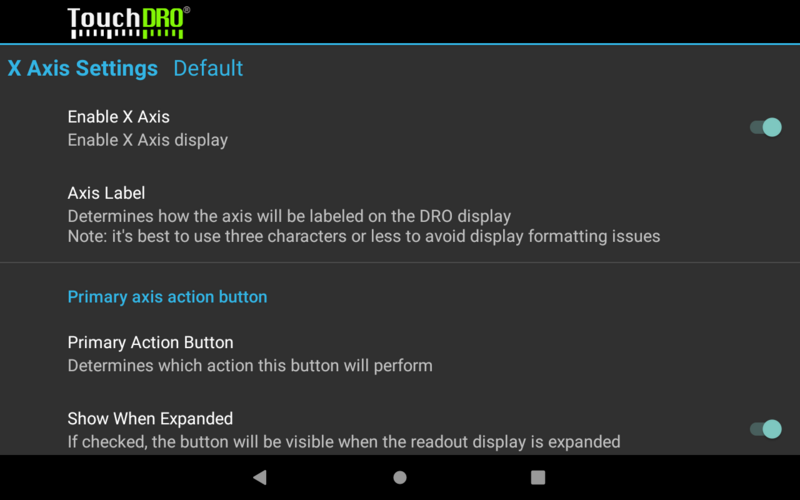
Axis Settings (X, Y, Z)

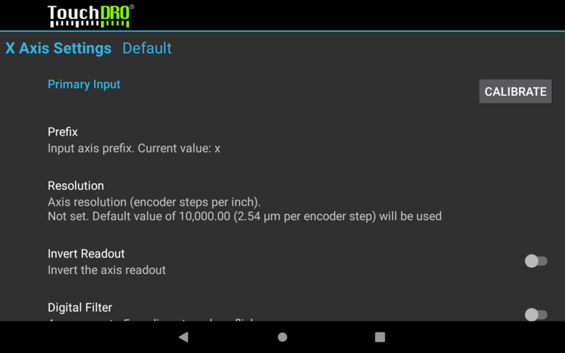
Axis settings are used to configure input axis parameters and per-axis readout display. This is where you will be able to customize TouchDRO for your specific machine and use case. The settings are covered in more detail in the Axis Settings action of the User Manual.

Note that by default, axis resolution is set to 10000 encoder counts per inch, which is likely not the appropriate value for your scales. To set the resolution to the correct resolution, please follow the DRO Calibration Instructions once you've installed your scales on the machine. For rough testing, you can set the resolution as follows:
- 5-micron glass and magnetic scales - 5080
- 1-micron glass and magnetic scales - 25400
- iGaging EZ-View and DigiMag scales - 2650
- Other capacitive scales - 2540
Below are the recommended initial settings for the common machine types:
Lathe
For most lathe setup, the following changes (from defaults) are most commonly used:
- Disable the Y Axis (by convention, the long axis on a lathe is Z and the cross slide is X)
- Set the Third Action Button setting to the "Hold/Set Position" function
- Enable Tachometer
- If you are using an RPM sensor, set the Pulses Per Revolution according to your encoder disk
- Otherwise, set Pulses Per Revolution to 0. This will allow you to directly enter the RPM in the main readout screen (and get the feed rate and cutting speed display)
Vertical Milling Machine
- The default configuration is sufficient for a milling machine setup with 3 scale inputs.
- If your mill has a separate quill movement (such as a common knee mill or many imported table top machines), you will need to enable the Secondary Input and set the Prefix to "w".
- For a two-axis setup (table movement only) disable the Z Axis output.
Horizontal Milling Machine
- For a 3-axis setup no changes from defaults are needed
- For a 2-axis setup (table movement only), disable the Y Axis.
Surface Grinder
- For a 3-axis setup no changes are needed
- In most cases, you will have DRO scales on the column (Y Axis) and on the front-to-back movement (Z Axis). For such a setup, disable the X Axis.
Combination Machine
- For a combination machine, you should use two separate Configurations.
- Use the Prefix setting, where you can map the inputs to the correct outputs, so each spindle configuration uses the correct coordinate system.
- Use suggestions above for each spindle configuration
