Avoiding Common DRO Scale Problems
Capacitive DRO scales such as Shahe, iGaging, AccuRemote, etc. have become a mainstay of DIY hobby digital readouts due to their affordability, availability, and other beneficial properties. They have also earned somewhat of an undeserved reputation of being unreliable, flaky, and easily damaged. However, when used with their original reading head, capacitive scales are very stable and reliable. The problems arise when they are connected together in a two- or three-axis DRO setup and subjected to shop noise. Fortunately, it's relatively easy to avoid many of the common problems by following a few basic guidelines. By following the five steps outlined below before powering up the DRO for the first time, you will be much more likely to end up with a reliable digital readout.
1. Ensure That All Pins Are Properly Wired
More than three-quarters of all scale reliability issues reported by TouchDRO users are the result of improper scale connection. Capacitive scales operate on micro Amps of current and can often work with Vcc and/or Ground leads completely disconnected, but the reading will be extremely unreliable. Furthermore, the Absolute DRO Plus and Shahe remote display scales provide their own clock and, at some positions, will produce a reading when the Data and Clock lines are reversed. Likewise, the reading will be all over the place.
If you purchased a pre-made TouchDRO board with Micro-USB connectors already pre-installed, all you need to do is to ensure that the male plugs are inserted securely. Otherwise, please follow your adapter's documentation to ensure that the pins are connected correctly and are attached securely.
2. Select a Correct Power Supply
Power supply issues are the second most common cause of TouchDRO stability and reliability problems. An incorrect power supply can create ground loops, inject noise into the system, or worse yet, permanently damage your scales and the TouchDRO adapter.
A good way to quickly confirm or rule out power supply problems is to temporarily power the TouchDRO adapter from a battery pack or a USB power bank. This will eliminate the potential unwanted mains ground connection and remove any switching power supply noise.
Output Voltage and Current
All TouchDRO adapters are designed to be powered from a DC power supply, but their requirements differ based on the type of onboard voltage regulator.
- Current revisions of pre-assembled TouchDRO adapters are designed for use with readily-available Micro-USB mobile device chargers that output regulated 5V DC and at least 200 mA. Powering them from an unregulated power supply can create brownout conditions that will lead to random resets while applying more than 5V will permanently damage the voltage regulator.
- Older adapters and DIY kits use a standard center-positive 5.5mm barrel power connector. The onboard voltage regulator can handle up to 13.8 Volts, but for best efficiency, the voltage should be about 2V over the scale's nominal supply voltage. In other words, when used with 3V scales, the TouchDRO adapter should be powered from a 5V power supply; when used with 5V glass scales, the adapter should be powered by a 7V power supply.
Switching vs. Linear Power Supply
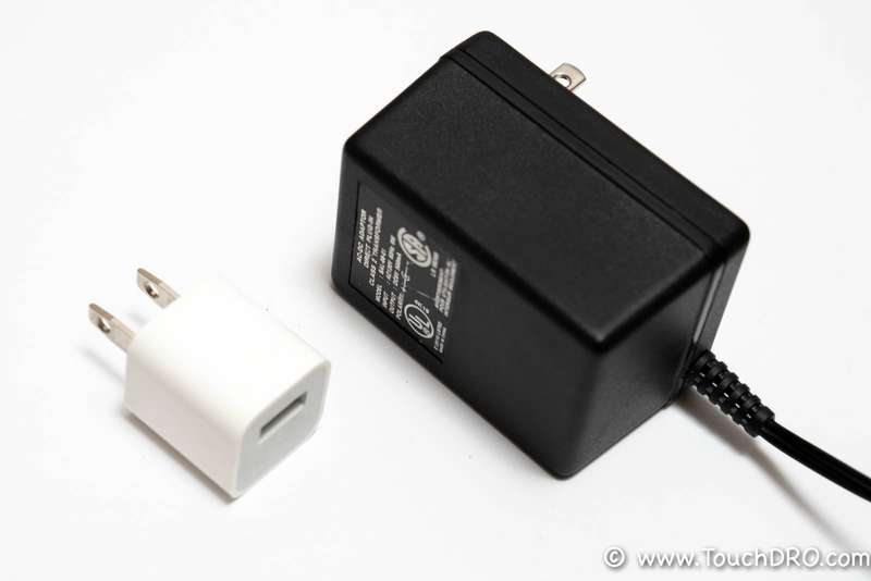
Old school "wall warts" had a very simple circuit that used a heavy transformer to step down AC voltage and a rectifier bridge to convert it to DC. Presently there is no benefit in using a transformer-based power supply with a pre-assembled TouchDRO adapter or DIY kit. On the contrary, many of the old wall warts have no built-in voltage regulators. Since the rated voltage is at full load, and TouchDRO draws very little current, the actual output voltage can easily exceed the rated adapter input voltage.

The new AC/DC adapters (such as phone chargers) use a more sophisticated switching power supply. When done right, they are more efficient and provide very clean and stable voltage up to their rated current draw. Unfortunately, there are ample opportunities to cut corners, so the cheap power adapters often have very poor voltage regulation and can even lack mains isolation.
- For TouchDRO adapters that use a Micro-USB power adapter, the best power supply option is a phone or tablet charger from a reputable brand. These chargers have very good mains isolation and provide a very clean and well-regulated 5 Volt supply.
- For TouchDRO adapters and DIY kits that use a 5.5mm barrel connector a good quality switching power supply should work very well. Just make sure that the rated voltage is within the appropriate range (as explained above) and the power jack is center-positive/barrel-negative.
Mains Isolation
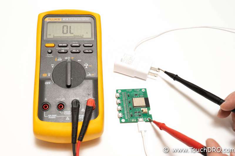
Mains isolation is very important for TouchDRO setups that use capacitive DRO scales. As mentioned earlier, some low-quality switching power supplies might omit an internal transformer to save cost. This will certainly create an undesirable ground loop, but more importantly, this can be very dangerous since it can electrocute you. To ensure that the DC power supply is isolated from the AC side, verify that there is no continuity between the AC connector prongs [including ground, if present] and the mounting holes of the TouchDRO adapter.

3. Ground the DRO Circuit
Any piece of wire can serve as an antenna picking up noise from the electronic fluorescent light ballasts, VFDs, PWM motor controllers and other things. Strong enough noise on the data or clock line can wreak havoc with scale readings. Pulses on Ground or Vcc lines can cause scale resets that manifest themselves in random zeroing out of the reading. Pulses on the clock or data lines will cause position climbing or erratic reading that jump all over the place. In most cases, the problem can be avoided entirely by properly grounding the circuit. Ideally, TouchDRO adapter board should be connected to the machine's body, which in turn, should be grounded, and scale cables should have their shielding braid or foil connected on one end to the ground as well.
Most capacitive scales need to have their frame connected to the Ground or Vcc (depending on the scale model). Models that use plastic reading head housings usually have a small metal strip that is connected to the internal PCB with a thin wire and makes contact with the frame. Due to sub-par soldering, the wire can easily break off the strip, resulting in unreliable ground connection. This usually results in erratic position jumps, especially when subjected to noise from a VFD or a motor. The easiest way to check this is to take the scale housing apart and check the connection visually. Alternatively, you can use a continuity meter and check that there is a solid connection between TouchDRO's ground and the scale's frame.
4. Eliminate Ground Loops
What are Ground Loops
Ground loops are just that, loops in the grounding circuit that are caused by too many grounding points. Issues associated with them are well known to home audio installers and audiophiles alike. In home audio systems they result in low-pitch hum through the speakers. In DRO setups, ground loops can wreak havoc with stability and reliability, and can even damage the scales. To some people this is completely counter-intuitive.
Why Are Ground Loops Bad
To understand why too many ground connections can be as bad as too few, consider an average DIY digital readout setup with three iGaging scales mounted to the machine's frame via metal brackets. Since iGaging scales have the frames connected to the negative lead, which in turn creates a ground connection between TouchDRO Ground net and the machine's frame. At the same time, TouchDRO ground is connected to the mains neutral via the AC/DC adapter. In most cases mains ground and mains neutral lines are tied together at the distribution panel. This creates a ground loop where one leg is the 6' of the scale cable and the other is several feet of wiring running to and from the distribution panel. The latter can cause serious problems for the scales. Consider the fact that at startup, a typical single phase AC motor can create a current spike of up to 5-10 times its normal running current. For example, a 5A motor can create 25-50A spike, which can cause short voltage jump in the mains neutral line (on the order of several volts). According to the Ohm's law Voltage = Current * Resistance. In this case, the resistance comes from the copper wire on the order of 0.25 Ohm per 100 feet, resulting in around a 6V spike in the neutral line. This creates a situation where for a brief moment where TouchDRO ground is at 6V instead of 0V, so the scale sees -3V rather than +3V Vcc. This can cause random scale resets and even damage.
How To Fix Grounding Loops
There are a few ways to deal with ground loops, especially the one caused by mains wiring. The easiest is to use mains-isolating power supply, as explained in the section above. Since the DC side will then be isolated from the AC mains, if a spike outlined above happens, it will not cause the Vcc reversal since the board can "float" up by 6V.
A more laborious method is to isolate scale frames from the machine's body by using plastic mounting brackets or some other means. This way TouchDRO's ground voltage can fluctuate but it will be harmless since the scales won't anchor their 0V to the machine and thus the Vcc reversal won't happen either.
5. Properly Ground 3-Phase VFD
Three-phase Variable Frequency Drives convert 60Hz AC voltage to DC and then back to variable frequency pulse-modulated AC voltage. The modulation frequency, also called "carrier frequency", is usually in the 1 KHz to 7 KHz range and can create all sorts of noise in the wiring. A VFD will come with a manual that lists specific grounding requirements. If not grounded properly, it will almost certainly create havoc with the electronic devices in the shop, and even the whole house in some extreme cases.
At the bare minimum, the frame of the VFD needs to be connected to the ground. It's also recommended to use a shielded 4-wire cable between the motor and the VFD. The shielding should be connected to the ground at one end, usually next to the VFD and the fourth wire should be used to tie the motor's ground to the VFD ground. This is especially important when using an inexpensive Chinese VFD, which often lack proper LC filter circuitry.
Conclusion
Vast majority reliability issues with iGaging EZ-View and other capacitive scales can be traced to faulty wiring, incorrect grounding, ground loops, noise created by VFDs, or similar PWM speed controllers. Common symptoms include random resets, intermittent position jumping and overall instability. When facing such symptoms, the beast approach is to check the wiring first to make sure all lines are connected reliably and if not, correct the problem. Second, verify that you are using the correct power supply and are connecting it properly. Third, ensure that any equipment that can produce noise is properly grounded. If after retesting the issue persists, make sure the board and the scale cables are shielded and properly grounded, but avoid ground loops since they can create additional problems.
