TouchDRO TDK-40/T Adapter KIT Manual
TouchDRO TDK-40 is an easy to build 4-axis DRO adapter kit that supports RS-422 (differential) and TTL (single-ended) glass and magnetic DRO scales and other 5V quadrature encoders. It uses the same powerful 32-bit architecture and differential input circuits as the TDA-4xx adapters, and offers the same speed and performance.
")
The kit includes all the parts needed to build a fully functional 4-axis DRO adapter with tachometer input. For exact details and ordering options, see the product page.


Features
Four RS-422/TTL Scale Inputs
The adapter comes with four scale inputs that support 5 Volt RS-422 and TTL quadrature encoders. This includes the vast majority of modern DRO scales (optical, magnetic and inductive) and NPN, PNP, and Push/Pull incremental rotary encoders.
TTL scales (also called single-ended) use two lines, A and B, to send the position data to the DRO. RS-422 inputs (also called differential) use a complementary pair for each line. The additional lines are often marked as A'/B', A-/B-, etc. Those lines carry inverted signals, so when line A is high, line A' is low, and vice versa. When the two inputs are combined by a special differential driver circuit, the noise is canceled.
Selectable Input Modes
Each of the four scale inputs has a configurable input mode. Quadrature is the default and covers standard optical, magnetic, and inductive scales; the other modes decode serial-protocol scales. The serial modes need TouchDRO Plus. Every TDK-40 has shipped with TouchDRO Plus since February 2026; earlier kits could be ordered without it, in which case the inputs are quadrature-only. The input mode is set per input in the Adapter Details dialog.
Bluetooth Connectivity with USB Mirroring
TouchDRO TDK adapters are equipped with a BlueTooth 4.2 transceiver and a high speed USB bridge. The firmware uses BlueTooth as the primary connection and mirrors the position output to USB, which can be used for real-time data capture, etc.
Tachometer Input
The TouchDRO TDK-40 adapter supports a tachometer input on the Mini-DIN connector. It can be used with any NPN or Push/Pull optical encoders or HALL effect sensors to measure the spindle RPM. The tachometer input can handle input frequencies ranging from 0.5 Hz to 100KHz with measurement error of less than 1%.
| Pin 1 | Pin 2 | Pin 3 | Pin 4 |
|---|---|---|---|
| Gnd. | 5V | --- | Tachometer |
Compatible DRO Scales
The adapters support DRO scales and rotary encoders that output 5V quadrature signals. This includes the vast majority of modern optical, magnetic, and inductive scales. Learn More
Technical Characteristics
Position Refresh Rate
The adapters send the scale position to the application every 40 milliseconds (25 times per second) when active, and once per second when idle.
Quadrature Signal Frequency
The maximum recommended quadrature signal frequency is 1 MHz. This is equivalent to a 1 micron scale moving at 4 meters per second, or a 5 micron scale moving 20 meters per second. The absolute maximum frequency is a bit under 4 MHz.
Tachometer Signal Frequency
The adapters have a low limit of 0.5Hz and upper limit of 100 KHz input frequency for the tachometer. In other words, the adapter will count pulses that are at most 2 seconds apart, and up to 1/100000 of a second. In terms of RPM, this translated to 30 RPM minimum and 6 million RPM maximum with a single-slit tachometer disk, or 3 RPM to 600,000 RPM with a ten-slit disk.
Minimum/Maximum Ratings
| Nominal | Minimum | Maximum | |
|---|---|---|---|
| Supply Voltage | 5 V | 4.0 V | 5.5 V |
| Current Draw | 15 0ma | 50 ma | 300 ma |
| Primary Scale Inputs | |||
| Signal Frequency | 1 MHz | --- | 4 MHz |
| Min Edge Separation | 250 ns | 250 ns | --- |
| Signal High Level | 5 V | 2 V | 5.5 V |
| Signal Low Level | 0 V | -0.3 V | 0.8 V |
| Tachometer Input | |||
| Tachometer Signal Frequency | 100 KHz | 0.5 Hz | 100 KHz |
| Signal High Level | 5 V | 2 V | 5.5 V |
| Signal Low Level | 0 V | 0 V | 1.1 V |
Assembly Instructions
When you receive the kit, it will be partially assembled:
- The ESP32 DevKitC is a self contained module and includes all of the support components needed for the microcontroller; the latest version of the TouchDRO firmware is already pre-loaded onto it.
- TDK-40 main board will be pre-populated with the surface-mounted ICs, LEDs and the rest of passive components.
- To finish the kit you will need to solder the ESP32 module to the board, add four 8-pin headers, wire the DB9 connectors to match your scales’ pinout, and build the enclosure.
Required Tools and Materials
You will need the following tools and materials:
- Soldering iron with a relatively fine tip
- Flux-core electronic solder. We recommend Kester #44 Rosin Core Sn63/Pb37 solder.
- Wire strippers
- Flush-cutting clippers
- Heat gun or a butane lighter (to heat up the shrink tubing)
- Philips #2 screw driver
- 3/16" wrench or a pair of needle nose pliers
Build Instructions
IMPORTANT: Before soldering the ESP32 module to the carrier board, power up the module from a compatible USB power supply and pair it with the TouchDRO application. Refer to the Connecting To TouchDRO Scale Adapter page if needed.
Make sure that the TouchDRO application is able to connect to the module, and stay connected for 20-30 seconds.
Step 1 - Install the ESP32 Module
Remove the ESP32 module from its antistatic bag and insert it into the main board, as shown below.
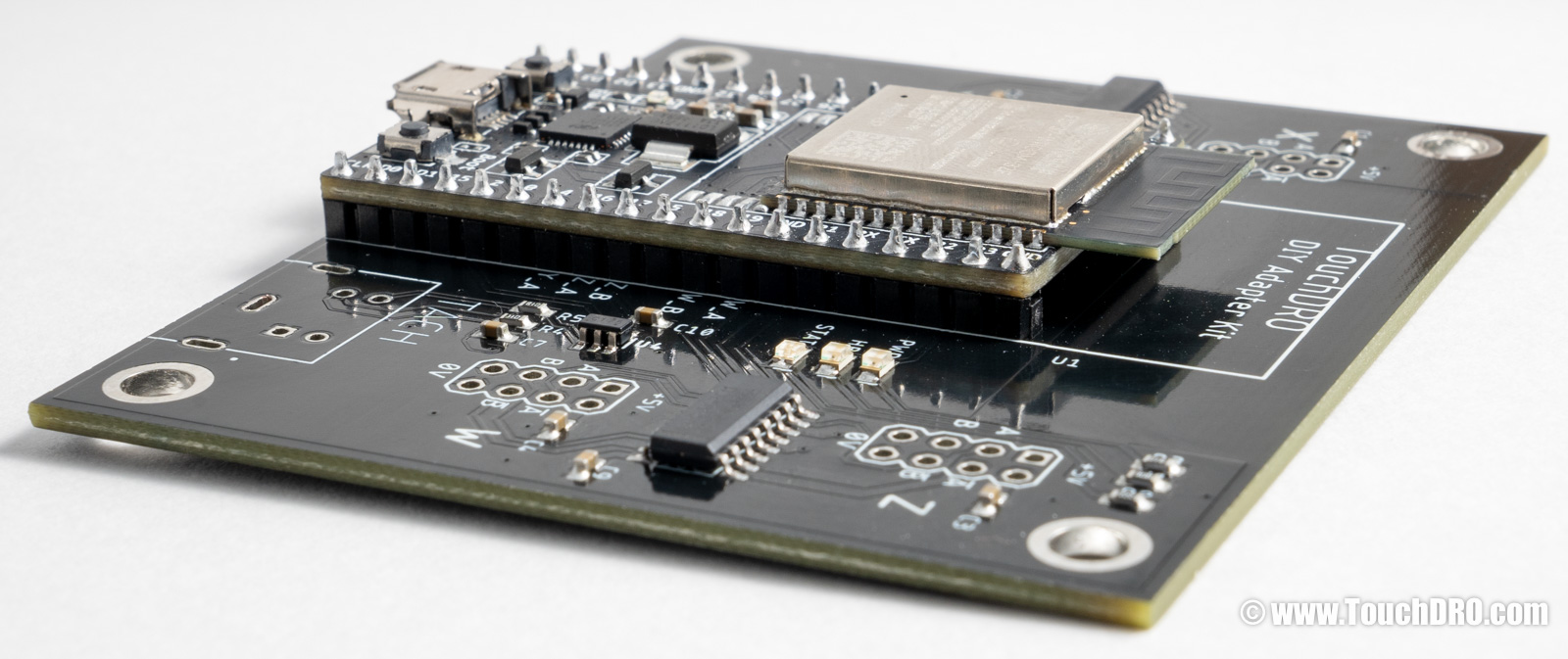
Press the module against the board and solder two diagonally opposed leads to hold the module in place and check that the pin header is sitting flush; adjust if needed.
Carefully solder the remaining leads. Make sure that the molten solder is wetting the pads and the leads, and creates a concave filet.
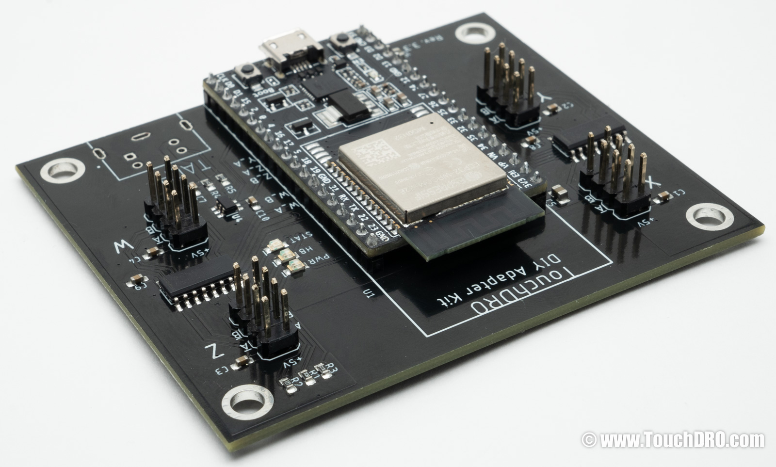
Step 2 - Install the Pin Headers
Insert the first pin header into its position and solder one of the pins while pressing the header by an opposite pin. Do not touch the pin you are soldering; you will get burned.
Repeat for the other 3 pin headers.
Lay the board face-down on a flat surface, press it down, and one-by-one briefly re-melt the soldered pins. This will straighten the connectors.
Solder the remaining pins, making sure that you don't create solder bridges between adjacent solder joints. The end result will look similar to the photo below.
Step 3 - Install the Mini-DIN Connector
Insert the Mini-DIN 4 connector into the main board and solder the pins as shown below.
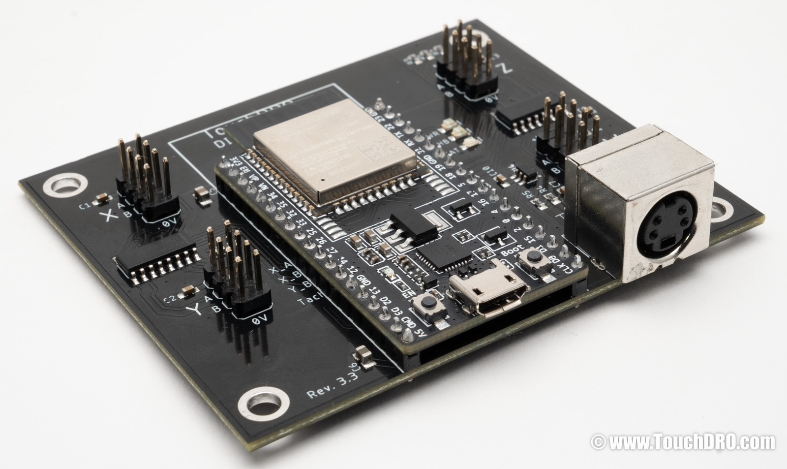
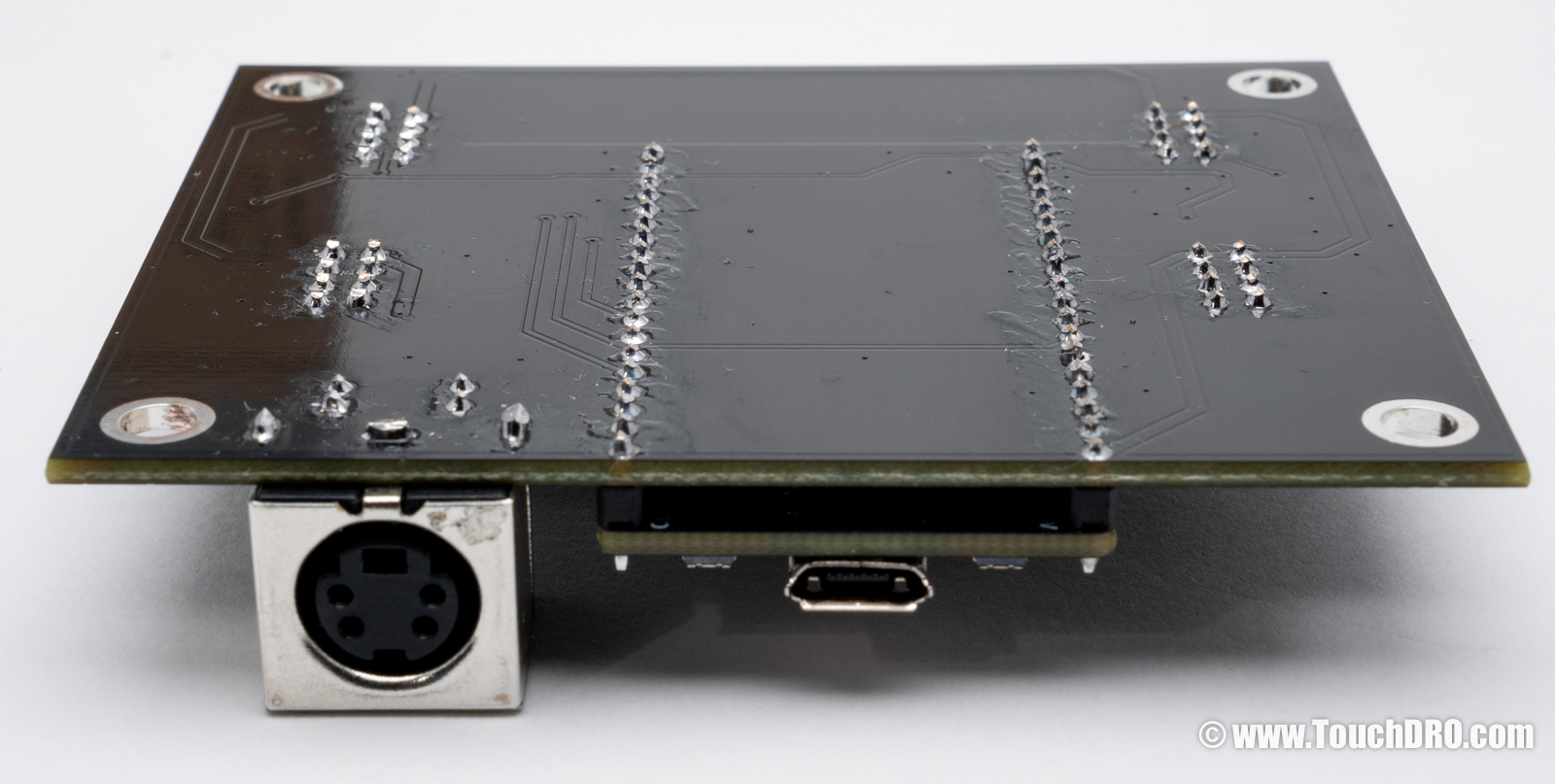
Step 4 - Clip the Protruding Pins
The pins on the underside of the board will protrude by a few millimeters. Using a pair of clippers, cut the pins so they protrude by no more than 2 mm.
Step 5 - Built the DB9 Connectors
Determine the Scale Pinout
Locate the pinout diagram for your scales and determine which pins will be used to connect it to the TouchDRO adapter. This information is usually included with the new scales, or can be obtained from the scale supplier. Alternatively, if you can't locate the relevant documentation, check the "DRO Scale Compatibility" to see if your scales use one of the standard pinouts. Finally, you might be able to reverse engineer the pinout using the "How to Find the Pinout of an Unknown DRO Scale" guide.
Depending on the type of your scales, you will use four or six wires per connector:
- TTL scales will use 5V, Ground/0V, A and B lines
- RS-422 scales will use 5V, Ground/0V, A, A', B, and B' lines
Prepare the Wires
The kit comes with 12 Dupont jumper ribbon cables.
- Cut about 70mm from one side of the cable, separate the wires, and strip about 3mm of isolation off the cut ends.
- Twist the wire strands together and tin them. The end result should look like the photo below.
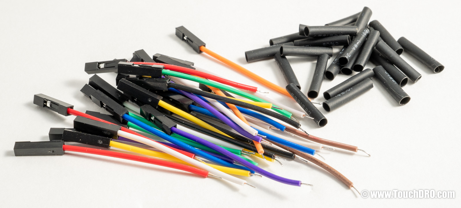
Cut the provided heat shrink tubing piece in half, and slide the resulting pieces over the wires you just prepared.
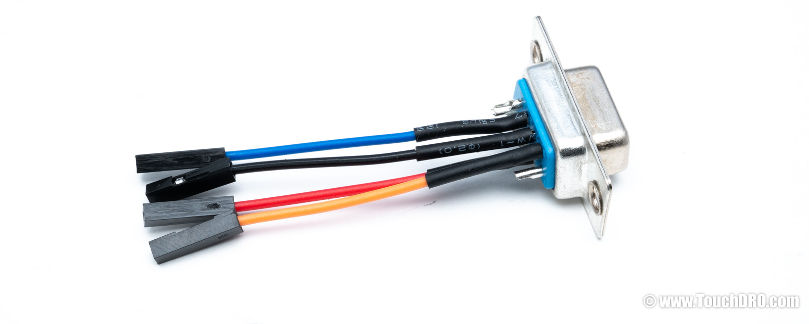
Solder the Wires
Build one connector according to your scale's pinout, but don't seal the heat shrink tubing. To ensure that the pinout is correct, plug in the connector into the board, and carefully plug in the scale making sure that the exposed wires are not touching anything conductive.
Power up the adapter, connect to it from the TouchDRO application and confirm that the readouts change when you move the reading head:
- When the scale is wired correctly, the readout will count up or down rapidly.
- If the readout is not changing when the head is moving, the wiring is incorrect. Power down the adapter and re-check the pinout.
- If the readout is jumping between 0 and 1 (or -1), either one of the lines (A or B) is not connected, or the complementary lines (A' or B') are mixed up.
If everything looks OK, solder the remaining three connectors.
Move the shrink tubing over the soldered pins on the DB9 connector and using a heat gun or a butane lighter, carefully heat it until it shrinks uniformly around the pins. Finished connectors should look like the photo below.
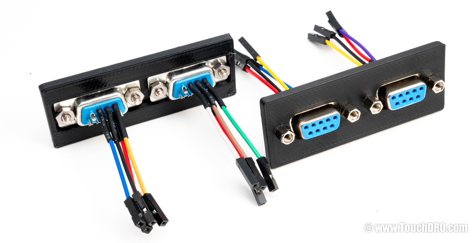
Step 6 - Attach DB9 Connectors to the Face Plate
Using two 4-40 jack nuts and two 4-40 nuts, attach each of the DB9 connectors to the side plates.
The end result should look like the photo below.
Step 7 - Assemble the Enclosure Bottom
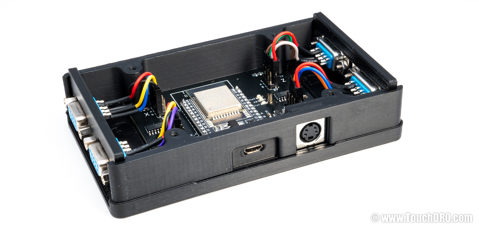
Place the PCB into the base of the enclosure. Use two included black "Plastite" screws to attach the front side to the base. Check that the Micro-USB connector is aligned with the opening and the edge of the module is flush against the plastic enclosure side.
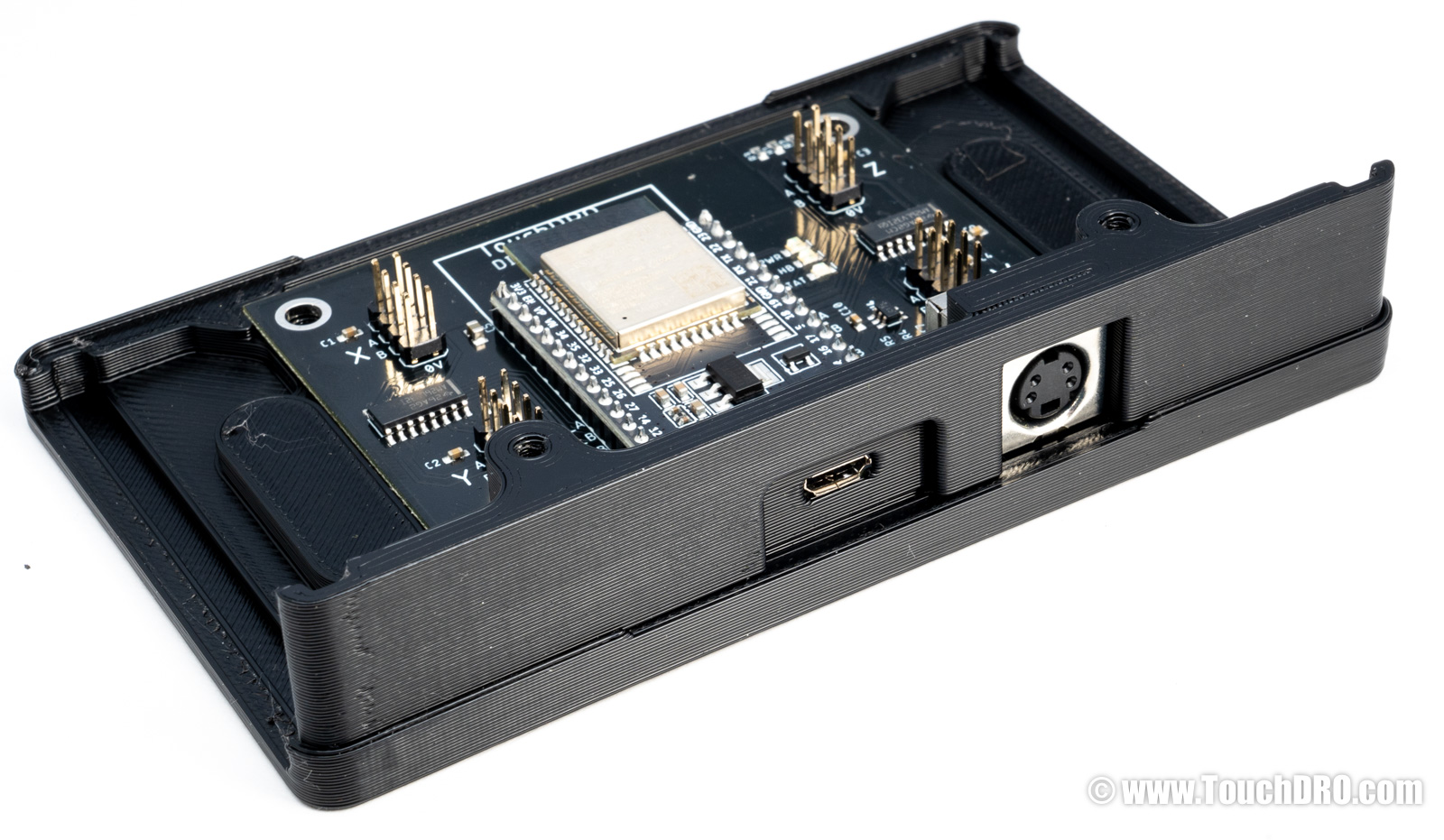
Attach the back side to the base.
Inset the DB9 connector plates into the slits as shown below and plug in the wires into the headers according to your scales pinout. Refer to the TDK-40 pinout diagram above if needed.
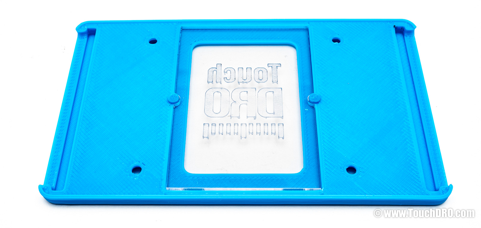
Step 8 - Assemble the Enclosure Lid
Remove the protective film from the acrylic insert and place it into the cutout in the enclosure lid. Note that the TouchDRO logo should be facing towards you.
Step 9 - Test the Adapter
Before closing the lid, it's a good idea to test the scale inputs to make sure that they are wired correctly.
Plug in the scales into the adapter.
Power up the adapter from a compatible USB power supply and pair it with the TouchDRO application. Refer to the Connecting To TouchDRO Scale Adapter page if needed.
Perform the initial configuration as described in the TouchDRO Initial Configuration guide. Once the application is configured, move the scale and confirm that the readouts respond to the movement.
If everything looks good, use the remaining four Plastite screws to attach the lid to the bottom of the enclosure.
Step 10 - Mount the Adapter
TouchDRO adapter communicates with the tablet wireless. This offers a lot of flexibility for adapter and tablet mounting. The following the tips below will ensure best performance and reliability:
- Mount the adapter in a spot where it will have a clear line of sight to the tablet. This can improve Bluetooth speed and eliminate any latency due to protocol errors.
- Make sure that the scale connectors are plugged in completely and the mounting screws are tightened.
- Use the included zip ties with self-adhesive anchors to provide strain relief for the connectors and the Micro-USB cable. (The adapter can be left connected 24/7; when not transmitting it consumes less than 50mA).
- If possible, mount the adapter to the wall rather than the machine. This will isolate it from the vibration caused by the spindle.