
Probe Profiles
A probe profile is a saved description of one probing device: what kind it is, how big its tip is, where that tip sits relative to the spindle, and which port it triggers on. TouchDRO keeps them in the "Probe Library", and the functions that use a probe ask you which profile to use rather than asking for the numbers again.
Three functions use probe profiles. The Indicate Workpiece function finds edges and centers in X and Y, and takes touch probes, edge finders, and cameras. The Set Z Reference function sets Z off a known surface, and takes touch probes and tool height setters. Measurement mode takes a profile as its reference instrument, so that a microscope bolted beside the head still reports positions on the spindle axis, and it takes touch probes and cameras. Each remembers the profile it was last used with, so all three can stay on different instruments.
Most shops own more than one. A 4 mm edge finder and a touch probe measure differently and sit differently in the spindle, so each gets its own profile and you pick between them at the point of use.
The Probe Library
To open the Probe Library, choose "Probe Library" from the application menu. It lists every probe profile available to the current machine profile, with each one's type and tip diameter on its second line.
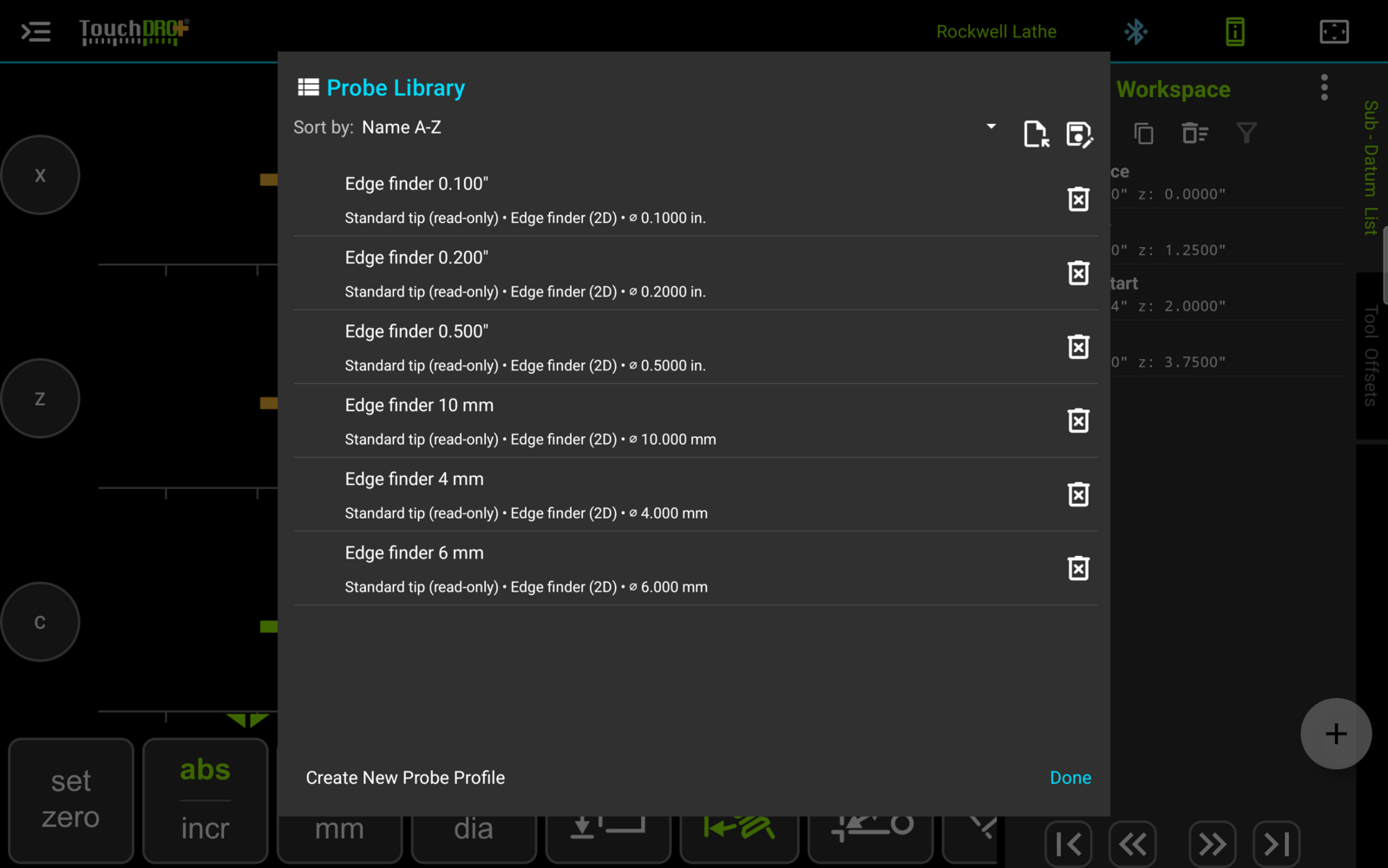
The "Create New Probe Profile" button at the bottom of the list opens an empty profile. The two buttons at the top import and export profiles, and the "Sort by" control changes the order the list is shown in.
Probe Types
The type is the first thing a profile records, and it decides everything else the profile asks for. TouchDRO supports four.
| Type | What it is |
|---|---|
| "Touch probe" | Triggers on contact; compensates for stylus diameter |
| "Edge finder (2D)" | Mechanical or electronic; compensates for tip diameter |
| "Tool height setter" | Sets Z from a known setter height |
| "Camera / microscope" | The crosshair is the reference; no tip to compensate for. Requires TouchDRO Plus |
The four types don't support the same functions, and it's worth knowing the differences before you buy rather than after.
| Function | Touch probe | Edge finder (2D) | Tool height setter | Camera / microscope |
|---|---|---|---|---|
| Edge finding, including bore and boss centering | Yes | Yes | No | Plus only |
| Setting a Z reference | Yes | No | Yes | No |
| Tip diameter calibration | Yes | Yes | No | No |
Only a touch probe does both edge finding and Z reference, which is the practical argument for owning one. Bore and boss centering is not a separate function: it is done inside the Edge Finder dialog by touching opposed edges and taking the midpoint, so any type that can find an edge can center a bore.
Creating a Probe Profile
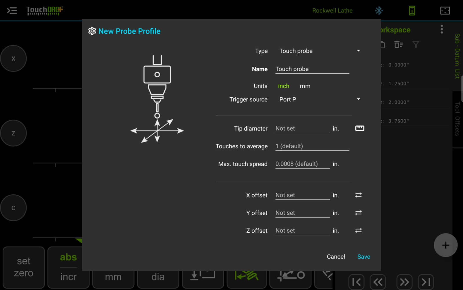
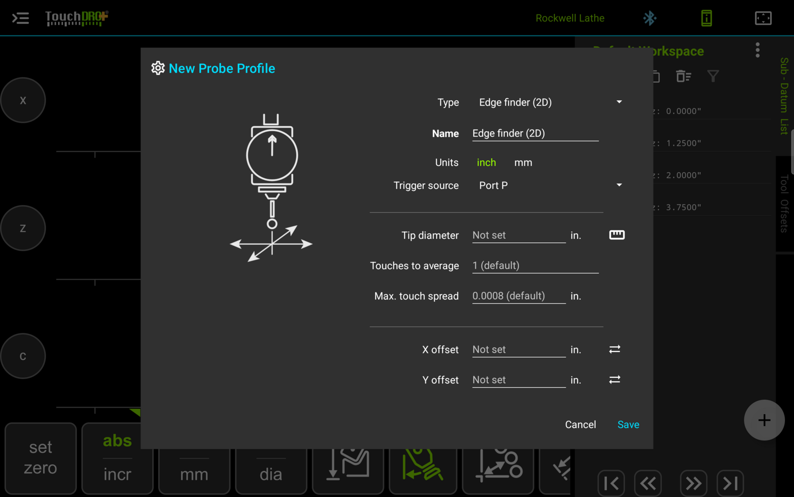
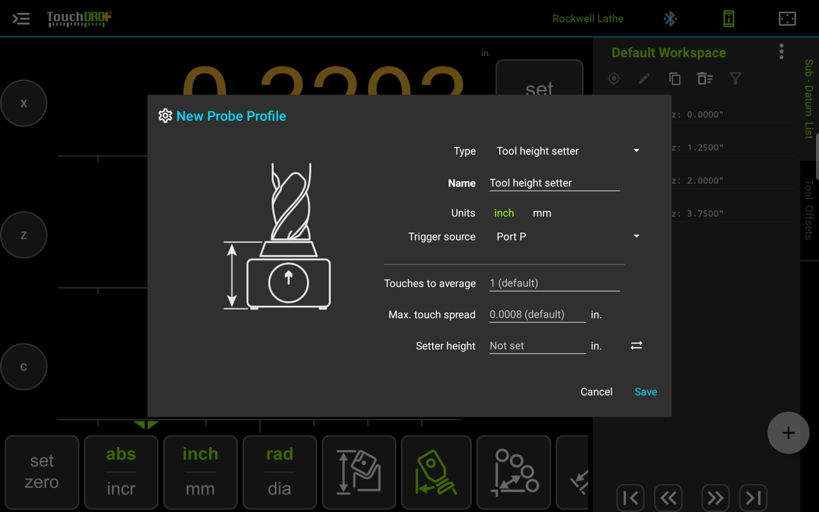
The type decides the drawing and the fields that follow it, so set it first. TouchDRO asks a touch probe for a tip diameter and three offsets; an edge finder for a tip diameter and two; a tool height setter for its height; and a camera for two offsets and nothing else.
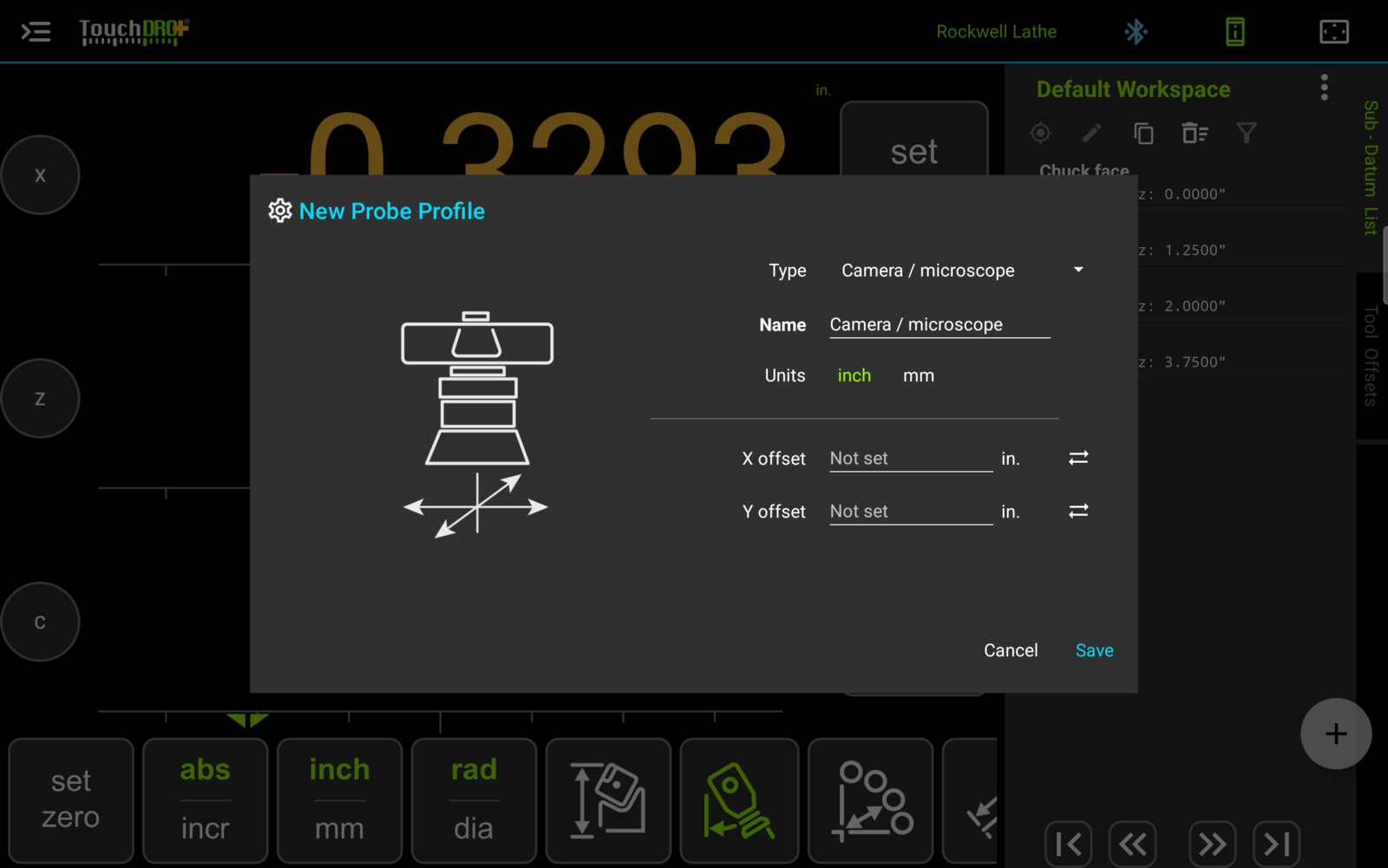
Name and Units
The name is what the probing functions will offer you, so it's worth naming the instrument rather than the type: "6 mm edge finder" tells you which one it is when there are three in the drawer.
The units belong to the profile rather than to the machine, so a metric probe can keep metric numbers on a machine you work in inches.
Trigger Source
The trigger source is the port on the adapter the probe is wired to. The choices are "Port P", "Port Q", and "None".
"None" is for an instrument that doesn't signal at all: a wiggler you line up by feel, or a setter you jog down onto by eye. You touch off and set the value yourself. Everything else about the profile still applies.
Tip diameter calibration needs a trigger port. A profile set to "None" can hold a tip diameter you typed in, but the calibration button (the ruler icon) will not be available, since the wizard has no way to tell when the tip has touched.
Tip Diameter
This is the diameter of the stylus or the edge finder tip, on the two types that have one. Enter the nominal figure, the one marked on the tool. It isn't something to go and measure: calibration replaces it later with a measured effective diameter.
The calibration button beside the field, the one with the ruler icon, runs the tip diameter calibration wizard. The wizard has its own walkthrough in the "Touch Probe Setup and Calibration" guide. The rest of this page calls it the ruler button.
Touches to Average and Max. Touch Spread
These two describe the instrument's repeatability, and they belong to the probe rather than to the machine. A kinematic touch probe repeats well enough to trust a single touch. A budget probe does better averaged over three, with a wider ceiling on how far apart those touches may land before TouchDRO objects.
Left blank, both fall back to a default, and the hint in the field names the figure actually in force. After a calibration run the spread hint reads "measured" instead of "default", because the run has established what this probe's own scatter really is.
Offsets
The offsets describe where the tip sits relative to the spindle axis. They are what allow the instrument to be mounted off-axis in the first place: a probe can sit on a bracket of its own, and TouchDRO will still report positions as though the measurement had been taken at the spindle.
A camera or microscope profile carries the same X and Y offset fields, and they matter more there than anywhere else. A camera is usually on a bracket of its own rather than in the spindle, and the two offsets are the entire reason a reading taken through the crosshair can be reported as a spindle position. They are also the whole of that instrument's accuracy, since there is no tip diameter to get right, so the measurement described below is worth taking care over.
How you arrive at the offsets depends on where the instrument is mounted, and there are two quite different cases. An instrument on a bracket of its own is meant to be off-axis, so the offsets are measured and entered. A probe held in the spindle is meant to be on-axis, and the work goes into making it so rather than into measuring how far off it is.
A Probe Held in the Spindle
A probe in the spindle doesn't strictly need to be on-axis, since the offsets can carry whatever is left, but careful centering reduces the error you get from imperfect clocking and lets the offsets stay at zero. The centering procedure, with the 180-degree flip check that finds the true trigger point, is part of the "Touch Probe Setup and Calibration" guide.
An Instrument on Its Own Mount
A probe on a bracket is measured rather than adjusted. The offset is found by locating the same edge twice, once with the instrument and once with a tool you trust, and the difference between the two readings is how far the instrument sits from the spindle axis.
The same measurement gives a camera or microscope its offset, and it's the figure TouchDRO applies to every position read through the crosshair.
- Clamp a square reference against the table, such as a 1-2-3 block or the fixed jaw of a milling vise, and check that it really is square to the travel.
- Locate an edge on it with the instrument, and mark the spot. The trusted tool has to reach the same spot, not just the same edge.
- Zero the readout on that edge.
- Swap the instrument for a reliable edge finder.
- Find the same edge again, at the mark.
- The readout now shows the offset. Enter it into the profile's X or Y field, or press the button at the end of that row to fill the field from the current reading.
Repeat the same sequence for the other axis.
The Z Offset
The Z offset is a separate quantity and isn't found by either procedure above. On a touch probe it is a genuine height offset. On a tool height setter it is the setter's own height, entered as a plain positive number. 2D edge finders don't use Z at all, and the field is switched off for them.
Standard Tips
TouchDRO ships with a set of ready-made edge finder profiles in common sizes, marked "Standard tip (read-only)". They can't be edited, because every machine profile sees the same ones. To work in a size they don't cover, or to change anything about one, create your own profile instead.
Deleting a Probe Profile
To delete a profile, press the delete icon on its row. TouchDRO will confirm first, and the confirmation says what goes with it: any function currently using that profile loses its probe selection.
Deleting one of your own profiles removes it from the machine profile it belongs to. Deleting a standard tip removes it everywhere, as described above.
Importing and Exporting Profiles
The two buttons at the top of the Probe Library move profiles between machine profiles and between tablets. They work on a TouchDRO probe profile file, which carries the extension ".tdprb".
Exporting
The export button writes every profile belonging to the current machine profile to one file, and TouchDRO confirms the name it saved under. The name carries the machine profile and the date, so several exports can live in the same folder without becoming a guessing game.
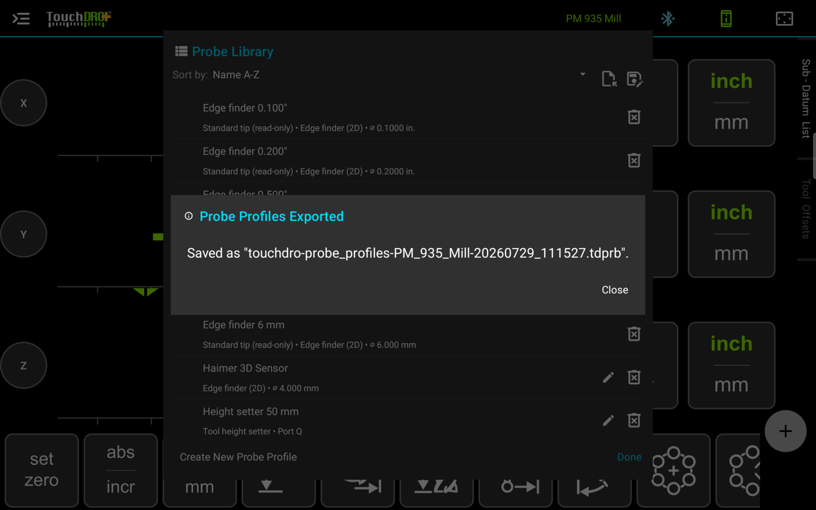
The standard tips aren't exported. They are the same on every install and arrive with the application rather than with a file, so writing them out would only import them back on the far side as a second set of duplicates. Everything you created is exported, and nothing you didn't.
An empty library still produces a file. A machine profile with no probes is a valid state to record, and importing the file restores exactly that.
Importing
The import button asks for a file and then shows you what it would do before it does any of it. Nothing is written until you press the import button at the bottom of the preview.
The line above the tabs says which machine profile the file came from and when it was exported. The "Operation" control decides how the file meets the library you have now:
- "Add as new records" adds every profile in the file, leaving what you already have alone. A profile that came from this same library will arrive as a second copy.
- "Update matching records" writes the file's version over profiles it recognizes, and adds the rest.
- "Replace all existing records" deletes the machine profile's current probes and puts the file's in their place. TouchDRO asks for confirmation first and says how many profiles it is about to remove. The standard tips are not affected.
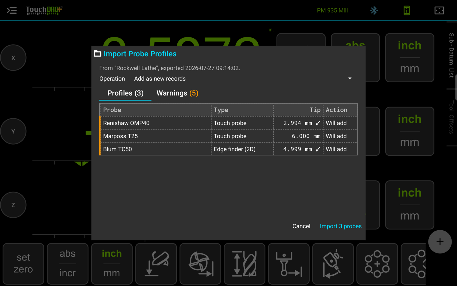
The "Profiles" tab lists what is in the file, one row each, with the type, the tip diameter, and what will happen to it. A check mark beside the diameter means that probe arrives with a calibration behind it rather than a typed figure.
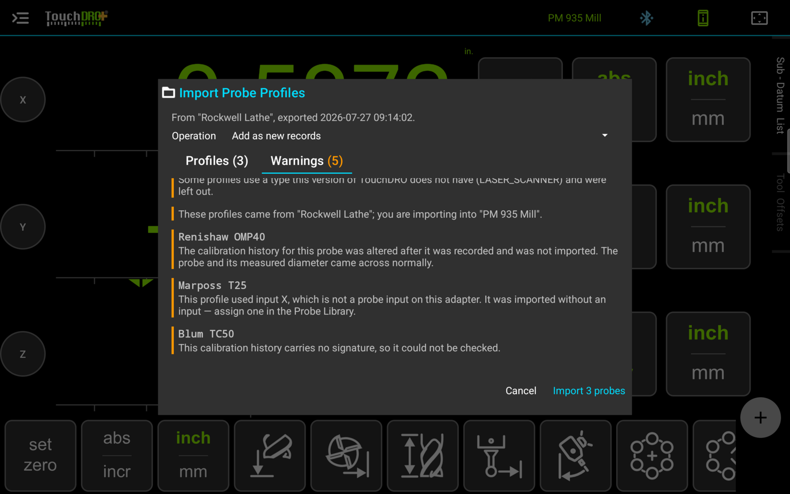
The "Warnings" tab is worth reading before importing rather than after. A warning is not a failure, and most of what appears there describes a profile that comes across usable with one piece missing. The two to act on are a probe whose trigger port doesn't exist on this adapter, which arrives without an input and needs one assigned in the Library, and a calibration history TouchDRO could not verify, which is left behind while the probe and its measured diameter come across normally.
Importing into a different machine profile than the file came from is allowed, and TouchDRO says so in the warnings rather than stopping you. It is a reasonable thing to do when two machines share a probe. It is also an easy thing to do by accident, which is why the warning calls it out.
Tip Diameter Calibration
The nominal diameter marked on a 2D edge finder or a kinematic touch probe is a starting point. During probing, the forces acting on the stylus cause the trigger point to be offset from the true center of the stylus, and depending on the probe model the difference can range from negligible to tens of microns. The calibration wizard, run from the ruler button, measures the effective diameter against a ring gauge and writes it into the profile, which gives more accurate measurements. The profile keeps the run it came from, and the information button beside "Max. touch spread" opens that record.
The whole procedure, from mounting and centering the probe through running the wizard and reading the result, is covered in the "Touch Probe Setup and Calibration" guide.