
Managing Tool Offsets on a Lathe
Accessing Tool Library
The list of stored Tool Offsets (AKA Tool Library) can be accessed by selecting the "Tool Library" option from the application menu drawer. This will bring up the "Saved Tools" dialog, shown below.
UI Elements

- "Sort by" selector - determines the sort of the list (on this screen only)
- "Import" button - used to import tool offsets from a CSV file; the preview works the same way as the one described in "Importing and Exporting Sub-Datum Coordinates"
- "Export" button - used to export tool offsets to a CSV file
- "Delete" button - used to delete selected offsets; the button is disabled until at least one item from the list is selected. The tool that is currently applied to the readout is shown in italics and can't be deleted, so its record doesn't show a Delete icon
- Tool Offset List - shows the contents of the Tool Offset Memory
- "Done" button - closes the dialog
- "Create New Tool" button - brings up the "Add Tool" dialog
How to Use Tool Offset List
This dialog can be used to enter new tool offsets, and edit or delete existing tool offsets:
- To enter a new tool offset, press "Create New Tool"; this will bring up the "Add Tool" dialog.
- To edit an existing tool, tap the record in the list; this will bring up the "Edit Tool" dialog, prefilled with the current details.
- To delete a tool, press the Delete (garbage bin) icon next to the relevant tool record and press "Delete" on the confirmation dialog, which names the tool.
- To delete multiple tools:
- Press and hold one of the records you want to delete until you see check boxes appear on the left
- Tap any other tool you want to delete
- Tap the "Delete" button at the top of the dialog
Add Tool Dialog

Name
Tool name (required) is shown in the tool dropdown list on the "Tool Offset" dialog. The name can contain any alphanumeric characters and the length is not restricted. For practical reasons (display size constraints) it's recommended to use tool names that are under 20 characters.
Description
Optional tool description can contain any combination of alphanumeric characters. This field is displayed only on this screen (and is included in the CSV file export).
Cutter Type
The "Cutter Type" selection marks the tool as either "OD/Facing" or "Boring". The choice is shown at the end of the tool's entry in the list, where a boring tool reads "ID", so a boring bar is easy to pick out among the outside tools.
X and Z Offsets
X and Z offsets (separate fields) are required fields that determine the tool offset. The value can be a positive or negative number.
Sync Button
The "Sync" buttons next to the offset fields pre-load the additive inverse of the current readout value for the given axis. In other words, the value will be the same number with the opposite sign. For example, if the current readout shows 0.250, the field will be preloaded with "-0.250".
The X offset is always a radius value, since it's the distance the cross slide has to move. When the readout is in diameter mode, the "Sync" button will load half of the displayed X reading. For example, a readout of 0.500 in diameter mode will be loaded as "-0.250".
"Sync" relies on two things. The surface you are touching has to be the one where the axis reads 0, and that zero has to have been set with the reference tool, or with a library tool applied. "Sync" subtracts the offset of the tool that is currently applied, so a tool synced while another library tool is in the tool post is still measured from your reference tool. The procedure is covered in "Programming Lathe Tool Offsets".
"Sync" needs a live reading. It shows a message instead of filling in a number when TouchDRO is not connected to the adapter, when a sub-datum is selected (the readout is showing the distance to it rather than the position), or in measurement mode.
Units
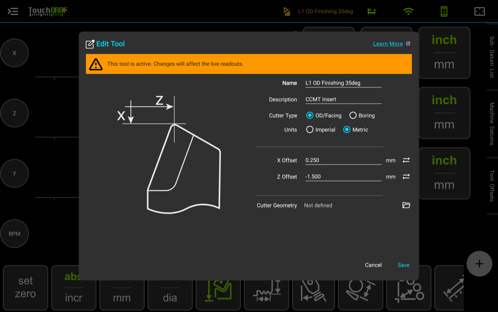
Each tool has its own units, set by the "Imperial" and "Metric" selection. The offsets are stored in the units the tool was entered in, and TouchDRO converts them when the tool is applied to a readout showing the other system. The selection can be changed later in the "Edit Tool" dialog, and the stored values are converted with it.
Cutter Geometry
A tool record can carry an outline of the cutter, drawn in a CAD program and saved as a DXF file. When the tool is applied, TouchDRO will draw the outline to scale in the graphical view, so you can see how much room the tool has in a bore or next to a shoulder. The outline is optional and has no effect on the offsets. The "Lathe Cutter Geometry" page explains how to prepare the drawing.
Until an outline is attached, the "Cutter Geometry" row reads "Not defined" and shows a folder button. To attach an outline, tap the folder button and pick the file. TouchDRO will convert the drawing and open the "Cutter Geometry Import" dialog, where you can check the result before attaching it.
Once an outline is attached, the row shows a small picture of the cutter and a Delete (garbage bin) button. To look at the outline at full size, tap the picture. To remove the outline from the tool, tap the Delete button. To replace the outline with a different drawing, remove it first, and the folder button will come back.
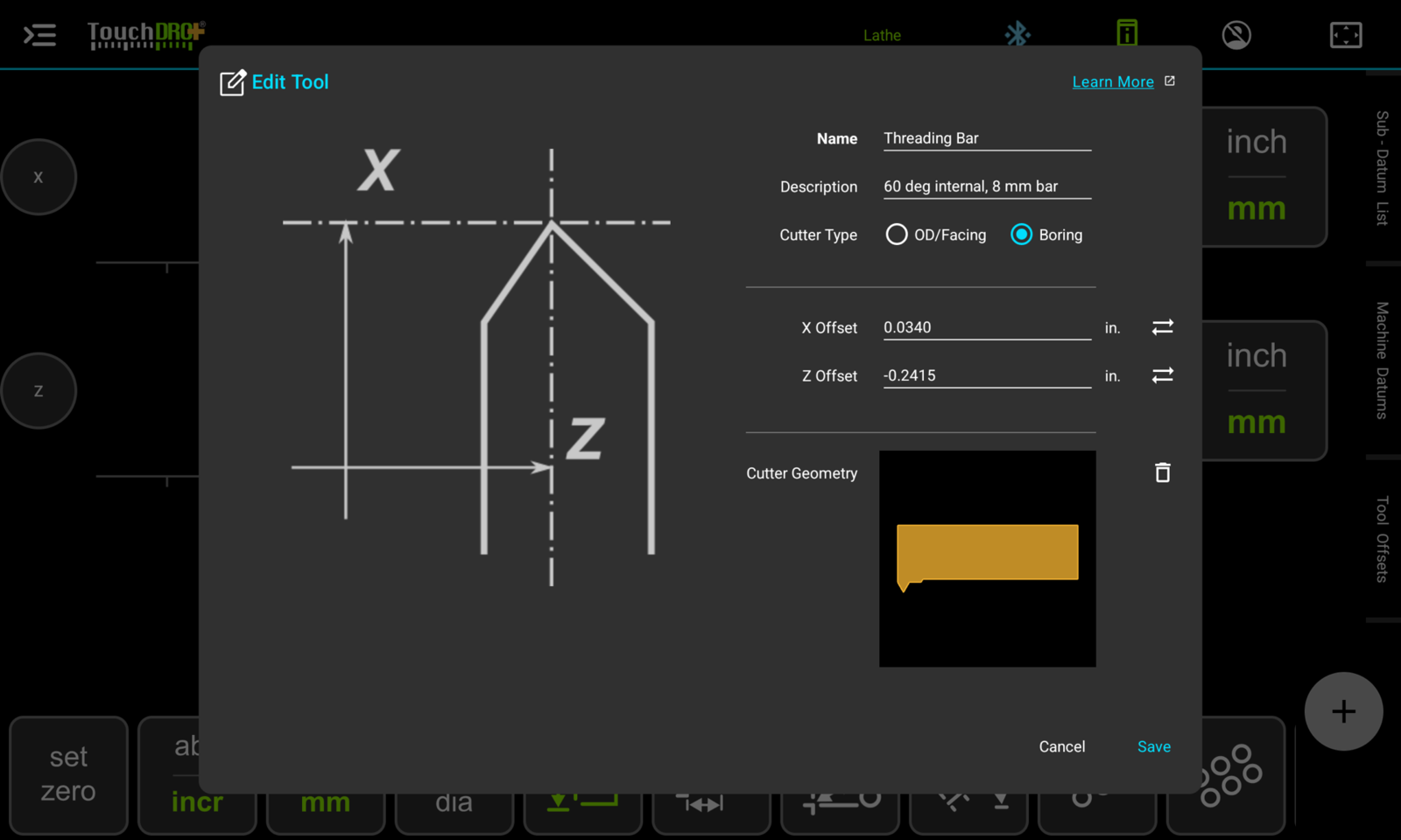
Edit Tool Dialog
The "Edit Tool" dialog is identical to the "Add Tool" dialog, with the only obvious difference that when the dialog is opened, the existing information for the selected tool is pre-loaded into the fields.
If you open the tool that is currently applied to the readout, a notice at the top of the dialog says "This tool is active. Changes will affect the live readouts." Pressing "Save" applies the new offsets to the readout right away. Deleting the applied tool removes its offsets from the readout.
Cutter Geometry Dialog
The "Cutter Geometry" dialog shows the outline at full size. It opens in two situations. Right after you pick a file, the dialog is titled "Cutter Geometry Import" and has the "Cancel" and "Attach" buttons, so you can check the drawing before it goes onto the tool. When you tap the picture of an outline that is already attached, the dialog is titled "Cutter Geometry" and only has the "Done" button.
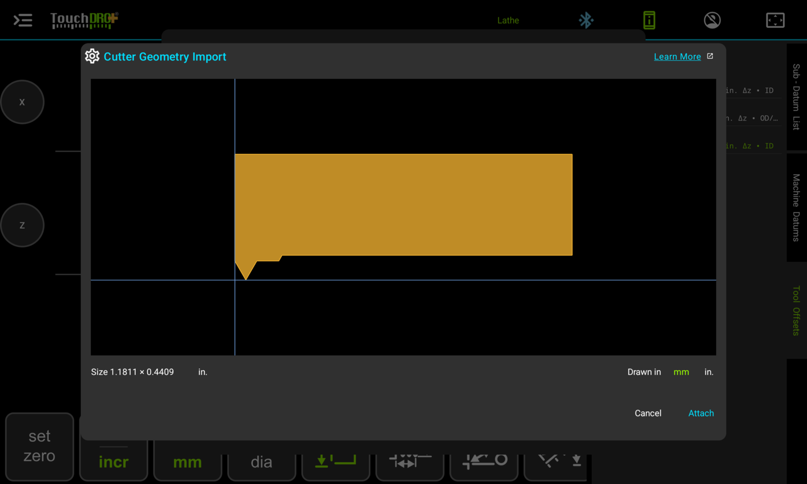
The two thin blue lines cross at the origin of the drawing. TouchDRO treats the origin as the point the X and Z offsets are measured from, so the lines should cross on the cutting tip. You can drag the picture to pan it, pinch to zoom, and double-tap to fit the whole outline back into the window.
Size
The "Size" row shows the overall length and width of the outline. The numbers are always in the units the readout is currently using, regardless of the units of the drawing. It's the quickest way to check that the drawing came in at the correct scale.
Drawn In
The "Drawn in" selector tells TouchDRO which units the numbers in the file are in. A DXF file doesn't always state its units, and TouchDRO reads such a file as millimeters. If the "Size" row shows a tool that is 25.4 times too small, the drawing was made in inches. Tap "in." and the size will be recalculated from the original file. When the size is already correct, leave the selector the way it is. The selector is only shown while importing, and TouchDRO stores the choice with the tool.
Messages in the Dialog
TouchDRO checks the drawing and shows a message above the picture when something doesn't look right. Apart from the first two, the messages are warnings, and the outline can still be attached.
- "This drawing has far too much in it to be a tool. It may be a drawing of the part rather than of the cutter." The outline is limited to 5,000 line segments after the curves are broken into short lines. Such a drawing can't be attached.
- "This drawing couldn't be read. Try importing it again."
- "The size below doesn't look like a cutting tool's. Check which units the drawing was made in." The outline is smaller than 1 mm or larger than 400 mm. In most cases the "Drawn in" selector is set to the wrong units.
- "The outline isn't closed, so the tool will show as a line drawing instead of a solid shape." TouchDRO closes gaps of up to 0.01 mm (0.0004″) by itself. A larger gap leaves the outline open.
- "Part of this outline doesn't join up. The solid shape is missing that part of the tool." Note that this warning is easy to overlook, since the picture looks finished. A part of the cutter is not filled in, and it's often the part near the tip.
- "The origin doesn't look like it's on the cutting edge. The X and Z offsets are measured from it." The origin of the drawing is away from the outline by more than 1 mm, or 5% of the tool's size for a large tool.
- "The drawing doesn't say which units it uses – check the size below." The file didn't state its units and was read as millimeters.