
How to Use a Tool Height Setter
When machining a three-dimensional part on a mill, swapping cutters can eat up a lot of time. Each time you insert a new cutter, you lose your Z reference and need to re-establish it. This is the time when you can make errors and scrap the part. A Z datum that is off by the difference between two cutters' stickout isn't an obvious mistake on the readout, and you generally find out about it at the bottom of a pocket.
The job also gets harder as it goes on. The first touch-off happens on clean stock, where the top surface is flat and you can put a cutter down anywhere on it. By the third tool, that surface may be a pocket, a step, or a contoured face. Sometimes the top surface has features that make it impossible to touch off the new cutter altogether.
What a Tool Height Setter Does
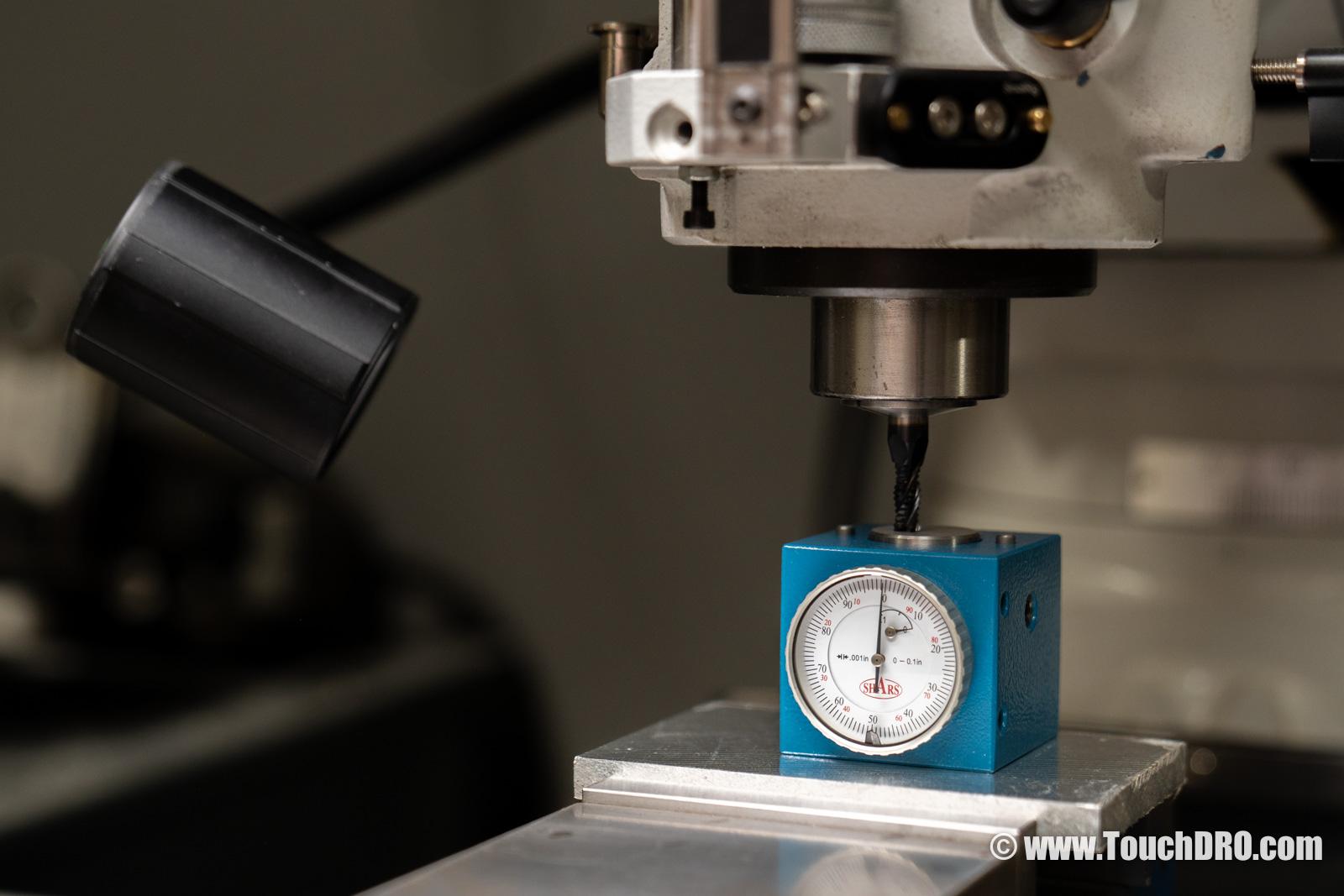
A tool height setter solves this by giving you a reference height that doesn't depend on the part. It's a small standard of known height, usually with a dial indicator on top, that you stand on a flat surface and lower the cutter onto until the dial reads zero. Because the height is known and repeatable, the digital readout can work out where the tool tip is without you ever touching the workpiece.
In TouchDRO, two functions use it, and they do different jobs. The "Set Z Reference" function provides a quick way to set the Z axis datum at the start of a job. The "Hold" function provides a quick way to swap tools once that datum is established. Most of the time you will use the first one once and the second one on every tool change after that.
Setting Up the Tool Height Setter
Before using the height setter, you will need to create a profile for it in the probe library. The profile stores the setter's height, which is what lets the application do the arithmetic for you later instead of making you add and subtract numbers at the machine.
- Open the "Probe Library" from the application menu
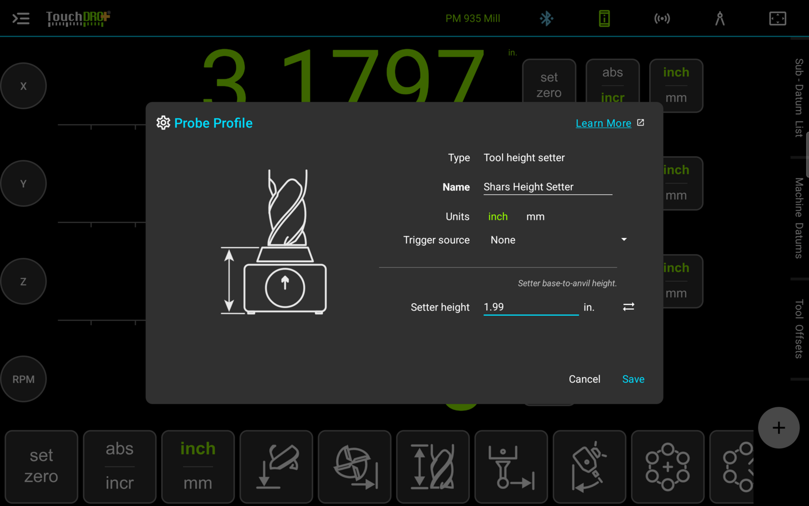
- Create a new profile, and set its "Type" to "Tool height setter"
- Give the profile a name, and pick the units the height will be entered in
- Leave the "Trigger source" set to "None"; a dial setter has no electrical connection to the adapter
- Enter the setter's base-to-anvil height into the "Setter height" field
- Tap "Save"
The rest of the profile controls are described on the "Probe Profiles" page.
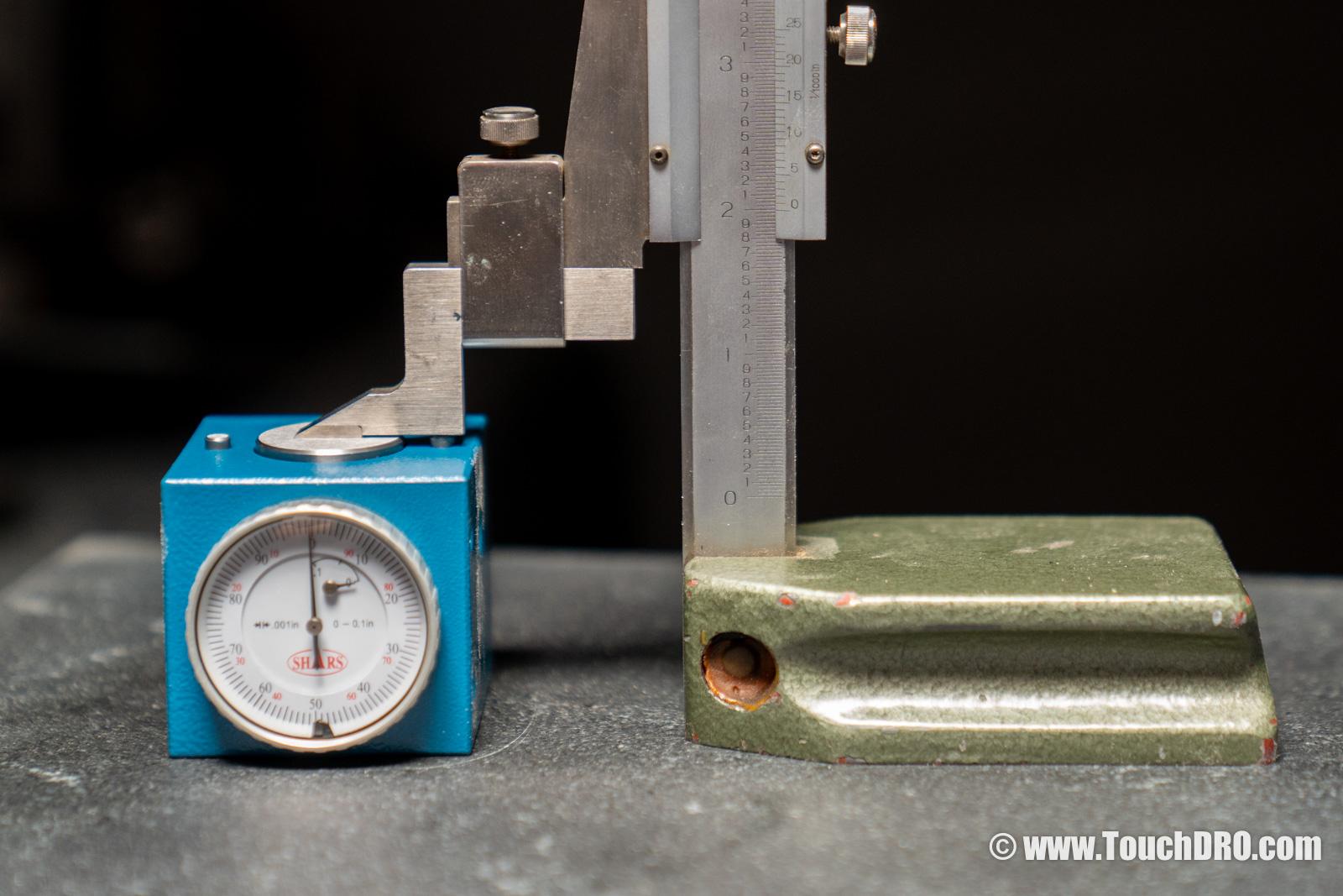
The height you enter is the one number the whole method depends on, so it's worth a minute of scepticism. Unless you purchased a name-brand unit, you shouldn't assume the setter is zeroed at its nominal height. A setter sold as 50 mm can easily leave the factory reading a few hundredths off, and that error will be carried into every datum you set with it. The easiest check is to measure the setter directly, with the dial zeroed, and enter what you measured: the setter in the photo below came out at 1.99 in. from base to anvil, and 1.99 is the number that went into its profile.
Setting the Initial Z Reference
The first touch-off establishes the datum for the part. Measuring the stock and entering its thickness is what puts the Z zero at the bottom of the part rather than the top, which is usually where you want it. Working from the bottom means a depth on the drawing is a number you can dial to directly: face the stock down until the readout shows the finished thickness, and you are done.
- Measure the thickness of the part or stock you are about to machine
- Insert the part into your milling vise, or whatever you need to do to hold it
- Place the tool setter onto the top surface
- Tap the "Set Z Reference" function
- Select the tool setter from the list
- Enter the part or stock thickness you measured
- Lower the cutter onto the setter's anvil until the dial reads zero. If you are using a feeler gauge or a piece of paper, lower the cutter until you feel the drag
- Tap "Apply"
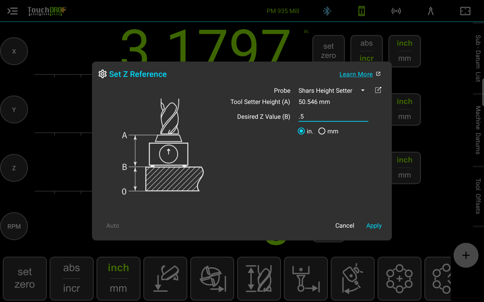
TouchDRO will do the math, and the absolute zero for the Z axis will be set at the bottom surface of the stock. The setter height comes out of the profile and the stock thickness comes from the field you filled in, so nothing needs adding up by hand. The individual controls in this dialog are described on the Set Z Reference Function page.
Swapping Tools Without Losing the Z Datum
Once the datum is set, you don't need to repeat that procedure for every cutter. Re-running "Set Z Reference" would mean measuring and re-entering the stock thickness each time, and it would mean putting the setter back on a top surface that may no longer be flat. The "Hold" function avoids both.
The idea is to use the setter as a transfer standard rather than as a measurement. You freeze the readout while the old cutter is sitting on the setter, change tools, bring the new cutter down to that same setter, and unfreeze. The readout picks up exactly where it left off, so the new tool inherits the datum from the old one. No arithmetic, no numbers to write down, and the part is never touched.
Because the setter is only being used as a repeatable height, it can stand anywhere convenient. It doesn't need to go on the part, which is the whole point once the top surface has features cut into it. It does, however, need to stay where it is between the two touch-offs: the method works because both cutters are brought down to the same physical height, so moving the setter to a different surface partway through will carry that difference straight into the datum.
- Place the tool setter anywhere on the milling table. In the photo above it is set on the fixed jaw of the vise
- Tap the "Z" axis label. This will open the Axis Details dialog
- Lower the cutter onto the tool setter anvil until the dial reads zero
- Tap the "Hold" button. The Z axis readout will turn gray, and the position will be frozen
- Swap the cutter. Once done, lower it onto the setter until the dial reads zero again
- Tap "Hold" again. The readout will turn green, and the position will stay the same as it was before you froze it
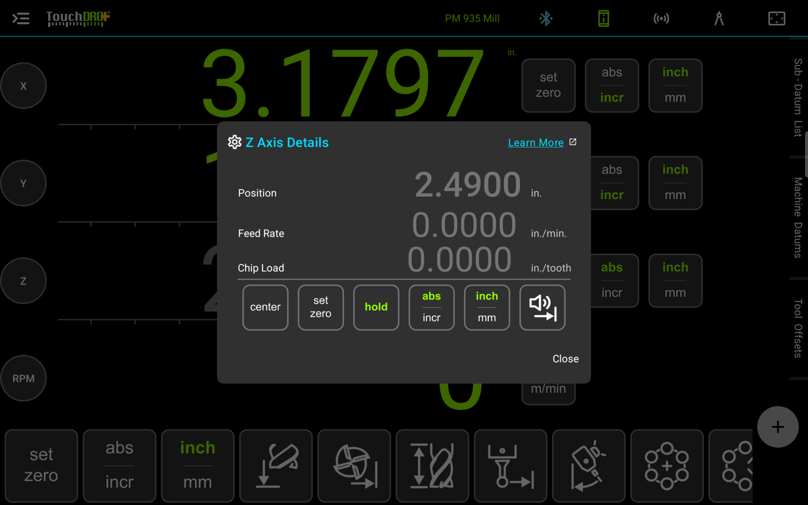
The gray readout is the visible sign that the axis is frozen. While it is gray the number on screen is the one captured at the moment you tapped "Hold", and it won't follow the quill or the knee. That is expected, and it's what lets you move the machine freely to get at the drawbar. If you need to abandon a hold without applying it, long-press the "Hold" button to cancel it.