
Cutter Radius Compensation
The scales on a milling machine measure the spindle, but the cut is made by the edge of the cutter, half a diameter away from it. Cutter radius compensation shifts the readout by that half diameter, so the number on the screen is the position of the cutting edge rather than the spindle centerline. Machinists usually shorten the name to "cutter comp"; if you know G41/G42 from CNC work, this is the readout version of the same idea.
Without it, working to an edge means adding or subtracting the tool radius on every move, and getting the sign right each time. That arithmetic is where dimensions get missed by exactly one cutter diameter.
The offset is kept as a separate tool offset coordinate system rather than being folded into the absolute or incremental origin. It can be changed or cleared at any point without disturbing anything you have already zeroed.
Opening the Dialog
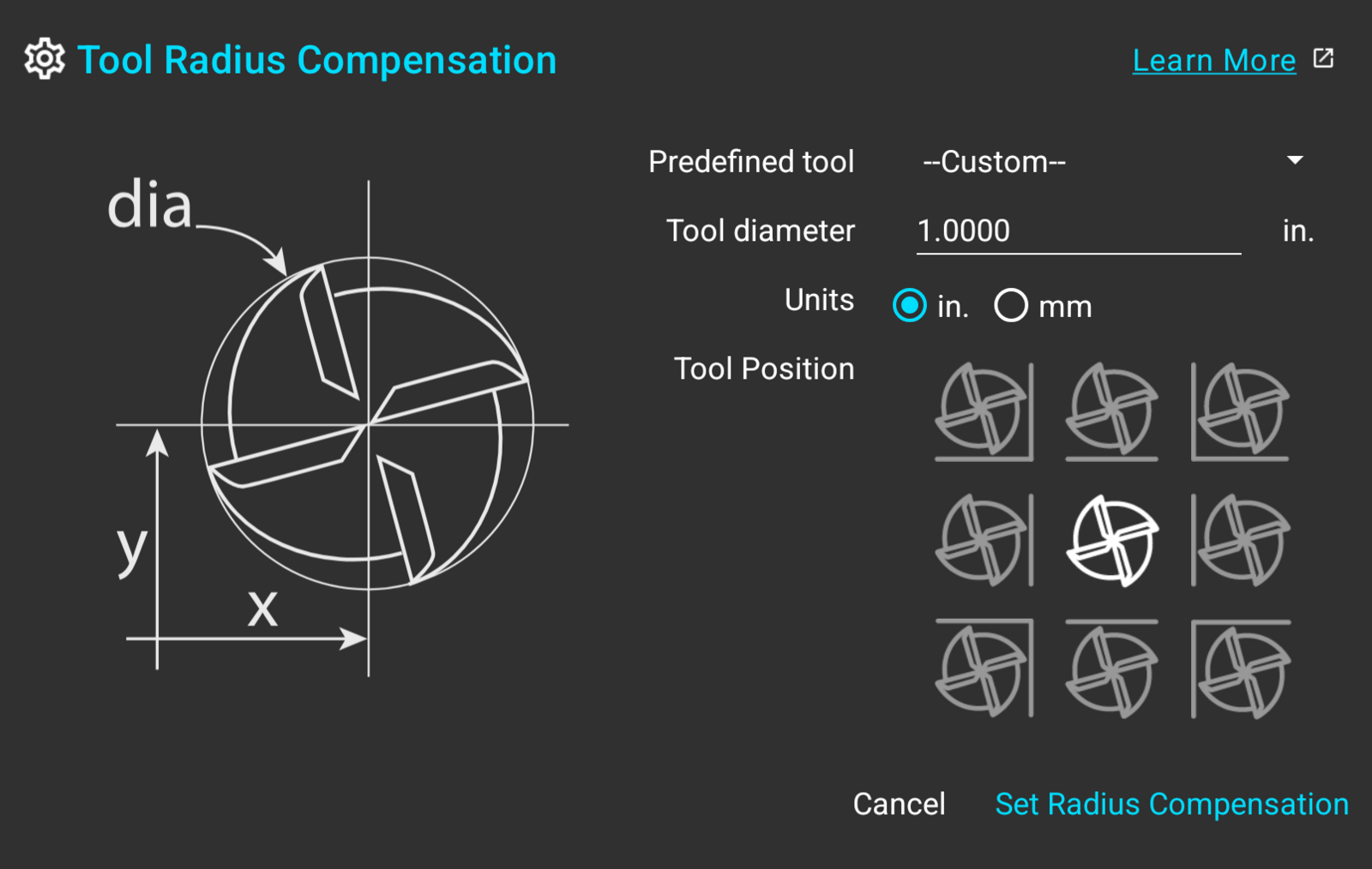
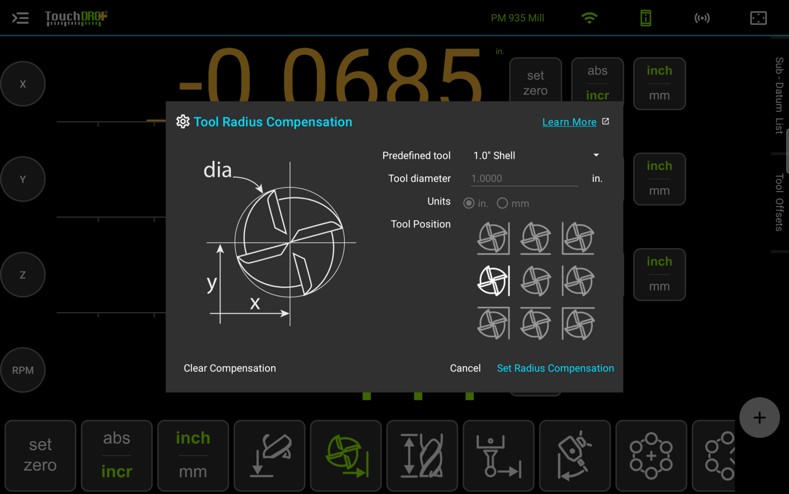
To open the "Tool Radius Compensation" dialog, press the "Tool Radius Compensation" button in the function strip.
Selecting a Tool
The dialog takes the cutter two ways: from the tool library, or as a diameter typed in for the job in front of you.
Predefined Tool
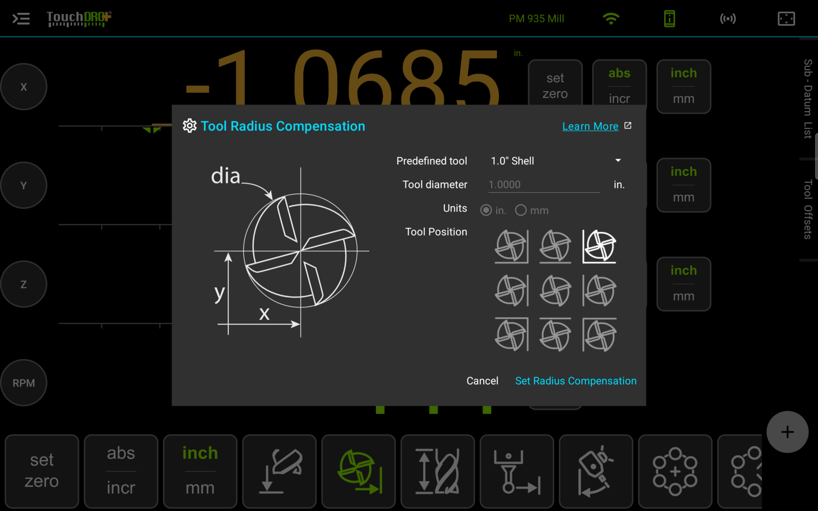
The "Predefined tool" dropdown lists the tools held in the tool library. Selecting one will fill in its diameter and units and make both fields read-only, since those values belong to the library entry rather than to this dialog.
This is the quicker route for a cutter you reach for often, and it keeps one measured diameter behind every use of that tool.
Tool Diameter and Units
Leaving "Predefined tool" on "--Custom--" enables the "Tool diameter" field and the "Units" selection. Enter the diameter of the cutter, not its radius, and set "Units" to match the figure you entered.
The units belong to the entry rather than to the machine, so a metric cutter can be entered in millimeters on a readout you are working in inches.
Tool Position
Knowing the diameter tells TouchDRO how far to shift the readout. The "Tool Position" matrix tells it which way.
The nine cells describe where the cutter sits in relation to the workpiece, and each one is drawn as the cutter against the edges it is working to. Picking the cell that matches your setup will offset the readout so it shows the cutting edge nearest those edges.
The Center Position
The center cell applies no offset, and the readout will keep showing the spindle position.
It is still worth selecting a tool this way. A selected cutter is what the chip load calculation needs, so the center position gives you a live chip load figure while leaving the readout uncompensated.
Pressing "Set Radius Compensation" applies the tool and the position. "Cancel" closes the dialog and changes nothing.
How Compensation Appears on Screen
The Readout Screen
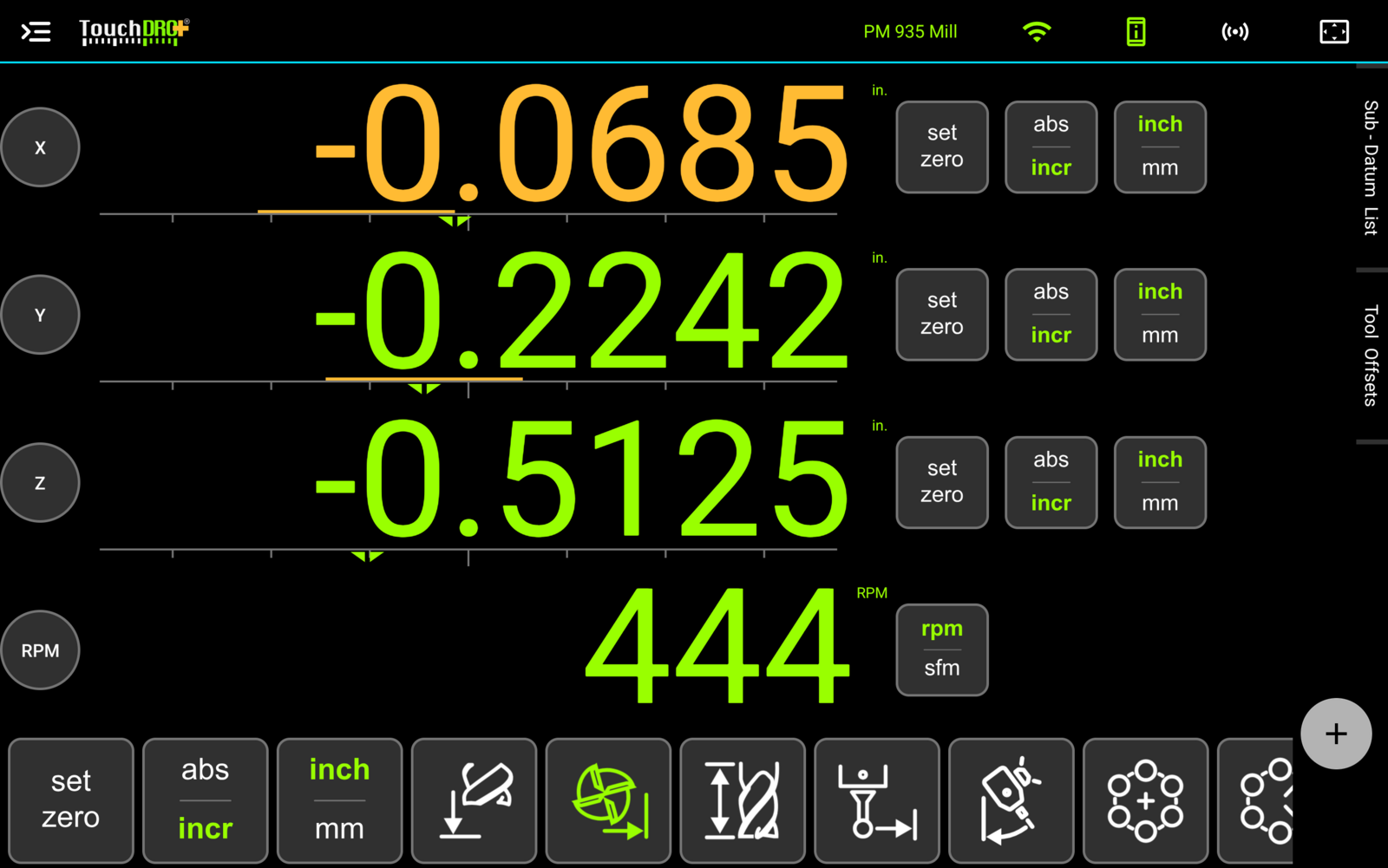
An axis carrying an offset will show its readout in amber rather than the usual color, so a compensated number is never mistaken for a plain one at a glance.
The position slider below the readout shows the direction of the compensation in relation to the spindle, which is the part that is easy to get backwards when you are only reading digits.
Graphical View
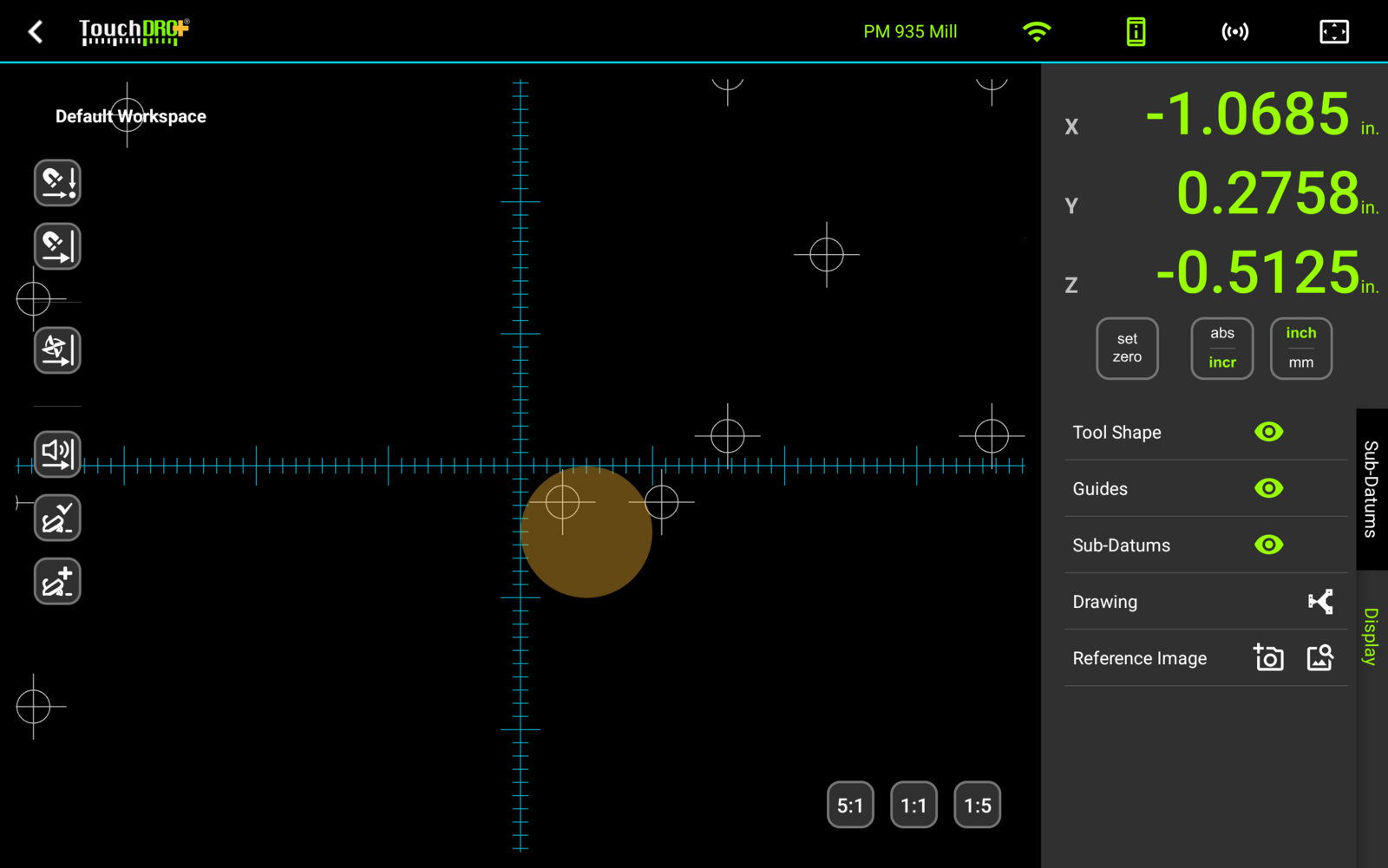
In the Graphical View display, the cutter is drawn as a partially transparent filled circle, sized to the tool diameter and placed according to the offset direction. It shows the material the tool is covering, which is the thing a set of coordinates cannot.
Hiding the Cutter
The cutter circle can be switched off without clearing the offset. In the "Display" panel of the Graphical View display, the "Tool Shape" row carries a visibility toggle that hides the circle while the compensation stays active.
This is useful on a crowded workspace, where a large cutter can sit over the sub-datums and guides you are trying to read.
Changing the Offset Direction
The direction usually needs to change several times over a single setup, so it can be changed without returning to the dialog. To bring up the same nine-cell widget in Graphical View, tap inside the cutter circle. The widget applies the new direction as soon as a cell is pressed.
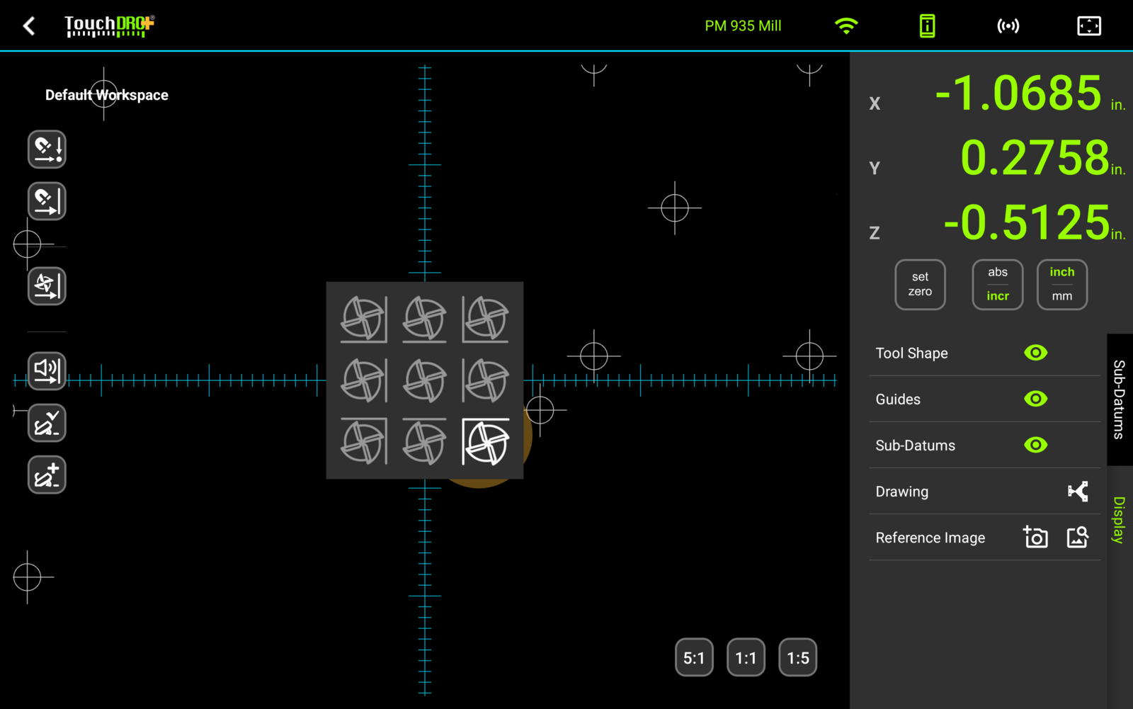
On a mill, the direction can also be set for you. With the "Auto Tool Offset" mode on, activating a guide will turn the offset toward it, so the readout shows the edge of the cutter closest to that guide. This is covered in "Working with Guides".
Clearing the Offset
There are three ways to remove the compensation:
- Long-press the "Tool Radius Compensation" button in the function strip
- Long-press inside the cutter circle in Graphical View, which will bring up the "Clear Tool Radius Compensation" prompt
- Open the dialog and press "Clear Compensation", which appears in the lower left corner while an offset is active
Clearing the offset returns the readout to the spindle position and removes the cutter from Graphical View. Nothing else about the setup changes, since the offset was never folded into the origins.
How to Use Cutter Radius Compensation
Squaring and Sizing Stock
Cleaning up a piece of rough stock asks two different things of the readout. While the first two faces are being cut, it has to show where the cut is landing. Once those faces are clean, it has to show how far the opposite faces are from them, which is the finished size of the part.
Compensation covers both, because the offset direction can be flipped once the first two faces are established. Those faces become the origin, and the readout then measures the remaining two against them.
Goal - square up a piece of stock carrying about 1/8" of excess material, then bring it to a finished size.
- Mount the stock in the vise with as much of it above the jaws as is safe to hold. The side of the endmill has to reach the full height of the faces being cut, so grip no more than the job needs.
- Load an endmill and open the "Tool Radius Compensation" dialog. Select the cutter under "Predefined tool", or enter its diameter and units.
- Set "Tool Position" to the lower left cell and press "Set Radius Compensation".
- Clean up the left face of the part. On the final pass, leave X where it is and long-press the X axis "Zero Set" button, which will set the absolute origin for X at the face you just cut.
- Clean up the front face the same way. On the final pass, leave Y where it is and long-press the Y axis "Zero Set" button.
- Change "Tool Position" to the upper right cell, either in the dialog or by tapping the cutter in Graphical View.
- Mill the right face until X reads the finished width, and the far face until Y reads the finished depth. The readout is measuring each cut from the face zeroed in step 4 or 5, so the number on screen is the dimension of the part.
Milling to a Guide Line
A pocket can be laid out as four guides, one per wall, and the cutter then worked out to each of them in turn. With the "Auto Tool Offset" mode on, activating a guide will turn the offset toward it, so the readout shows the cutting edge facing that wall and reads zero when the wall is at size.
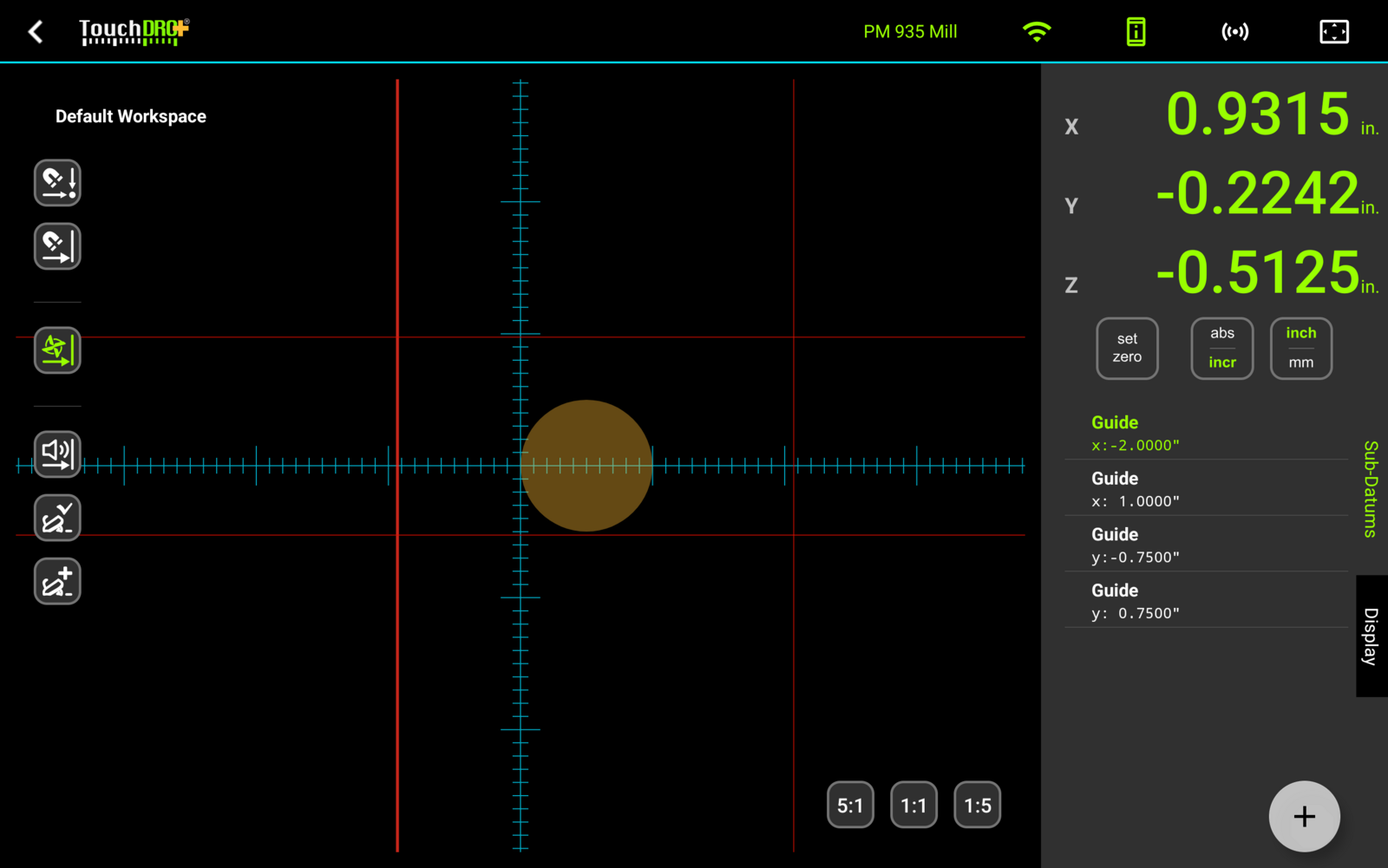
Worked examples for a slot and a rectangular pocket are in "Working with Guides".