
Measurement Functions
A measuring function takes a set of positions you locate on the part and works out a dimension from them. You supply the points with your instrument, and TouchDRO does the geometry: the straight-line distance between two features, the angle an edge runs off square, the center and diameter of a bore.
Each one is a calculation rather than a reading. That is what puts a number on features nothing can sit on, like the center of a hole or the corner two edges would have met at.
The measuring functions run down the left edge of the graphical view whenever measurement mode is on. Set your origin first with the "Indicate Workpiece" function, since every coordinate a measurement reports is stated from there.
The Measuring Functions
Each function takes a fixed number of points and reports what it can work out from them.
- "Point"
- Records a single position. The result is one "Position" row, ready to store as a sub-datum or to send to the log with a note: the record for "the edge of the boss is here".
- "Point-to-Point Distance"
- Measures between two positions: hole to hole, edge to edge, feature to feature. The result gives the straight-line distance, ΔX, ΔY and the midpoint. To set a datum in the middle of a plate, capture its two edges and save the midpoint. Capture the points in either order; the signs of ΔX and ΔY follow the order you chose, so they tell you which way you went.
- "Circle from 3 points"
- Fits a circle through three points on a circumference: a bore, a boss, or a hole in a plate. The result gives the center and the diameter; you can save the center as a sub-datum and add the circle to the drawing. Spread the points around the arc, since three bunched on one side still define a circle but a small error in any of them moves the center a long way.
- "Line Angle"
- Measures how far an edge runs off square, from two points along it. The result gives the angle against each axis, signed, so it tells you which way the edge leans and which way to tap the part. Spread the points as far along the edge as you can reach; the angle error is roughly the point error divided by the separation, so two points close together give a number nobody should trust.
- "Angle Between Lines"
- Measures the angle between two edges, from two points on the first and two on the second. The result gives both angles, since two lines make two of them, along with the point where the edges would meet even if you never touched the corner. Parallel edges read 0.00°.
Taking a Measurement
To start, tap a function in the strip. TouchDRO will hide the other functions and open a card in the upper-left corner of the graphical view. That card is the whole interface for the measurement: the slots the function needs, a prompt for the point it wants next, and the results once it has enough of them.
The prompt under the slots names the point being asked for, so "Locate point #1 on the first line" and "Locate the third point" tell you where you are in the sequence.
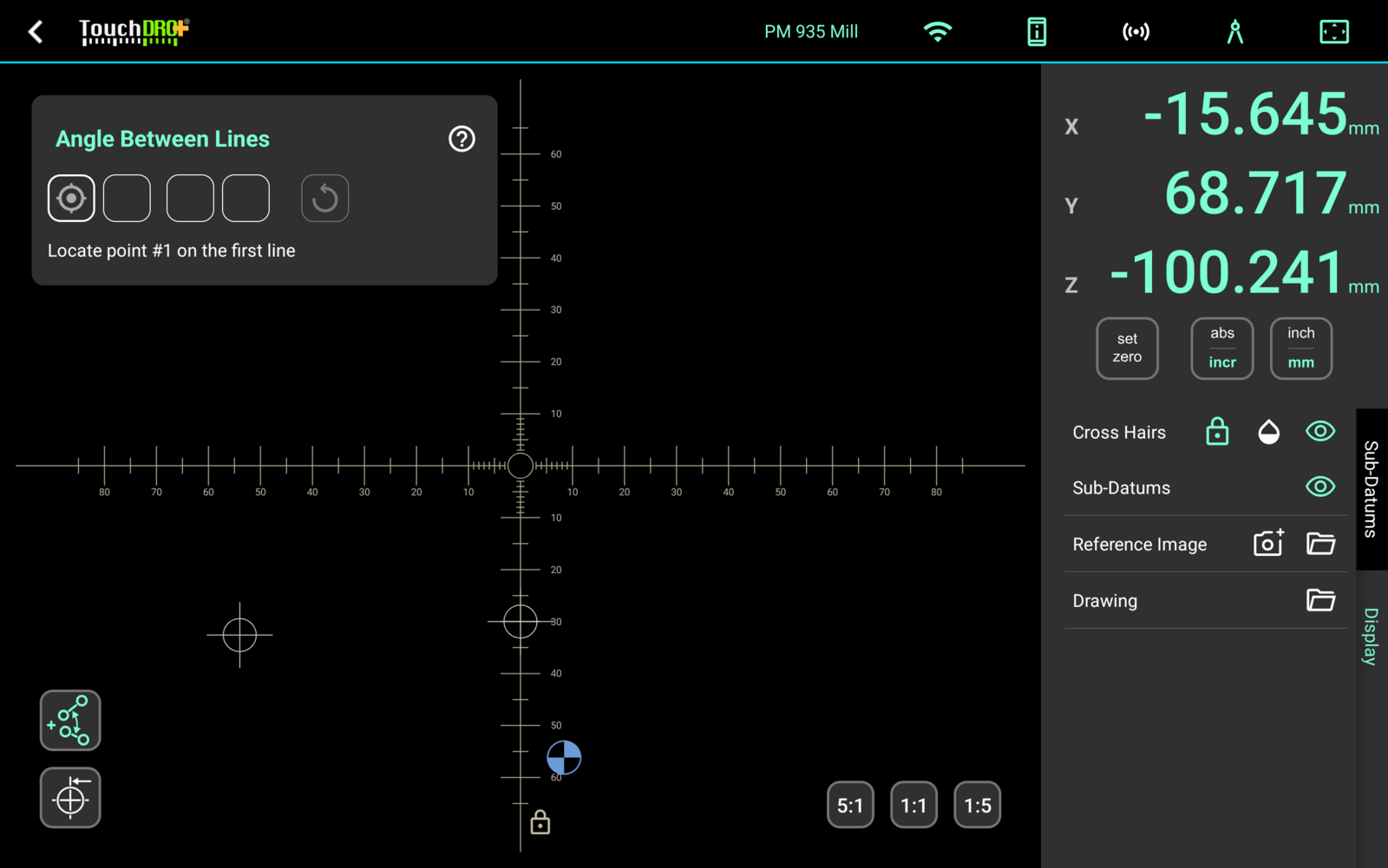
"Angle Between Lines" draws its four slots as two pairs with a wider gap between them, so you can see at a glance which points belong to which edge.
How each point gets captured depends on the instrument you selected, and its probe profile is where that is settled.
A touch probe or an edge finder sends a trigger signal to TouchDRO. With one of those selected, the function arms the instrument and listens for it: touch off the feature and the point lands in the lit slot on its own.
A camera, a microscope, or a spindle-mounted "wiggler" with a needle tip sends nothing back. With one of those selected, line the feature up under the crosshairs or the tip and tap the lit slot to latch the position yourself.
A probe profile can also ask for several edge triggers to be averaged. That averaging belongs to the "Indicate Workpiece" function; a measuring function takes one trigger per point.
Point Slots
A slot says two things at once: whether it holds a point, and whether it is the one waiting on you. Weight and color carry both.
- Empty
- Waiting for an earlier point. A thin white outline and no glyph.
- Lit
- The slot your next capture will fill. The same white as an empty slot but drawn heavier, with a reticle that pulses.
- Captured
- Holds a point. Mint, with a check. Long-press it to release the point.
- Flagged
- Holds a point TouchDRO flagged, described below. Amber, with the same check; long-press releases it the same way.
Releasing a Point
To release a captured point, long-press its slot. The released slot becomes the lit one and your next capture fills it, so you can replace one bad point in the middle of a set without starting the measurement over.
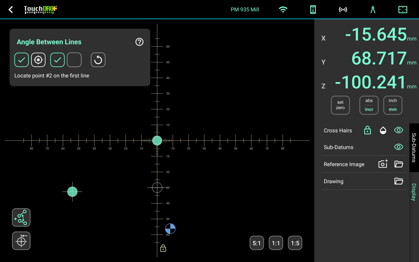
The reset button clears every slot along with the note and starts the measurement over.
Flagged Points
When a probe with a tip radius touches an edge, TouchDRO captures the center of the tip, which sits one radius away from the edge itself, in whatever direction the tip came from.
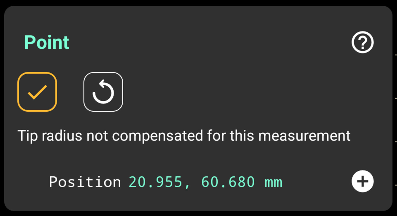
The three functions that fit geometry correct for that automatically, since the fitted line or circle tells them which way the tip approached. "Point" and "Point-to-Point Distance" have no geometry to take that direction from, so in those two TouchDRO flags a point captured with a tip-bearing probe. The slot is outlined in amber, the point is drawn in amber on the canvas, and the card reads "Tip radius not compensated for this measurement".
Saving a Result
Every result the card can save carries a "⊕" button beside it. You can store the center of a circle, the midpoint of a distance, or the intersection of two lines as a sub-datum, and add a measured circle to the drawing itself.
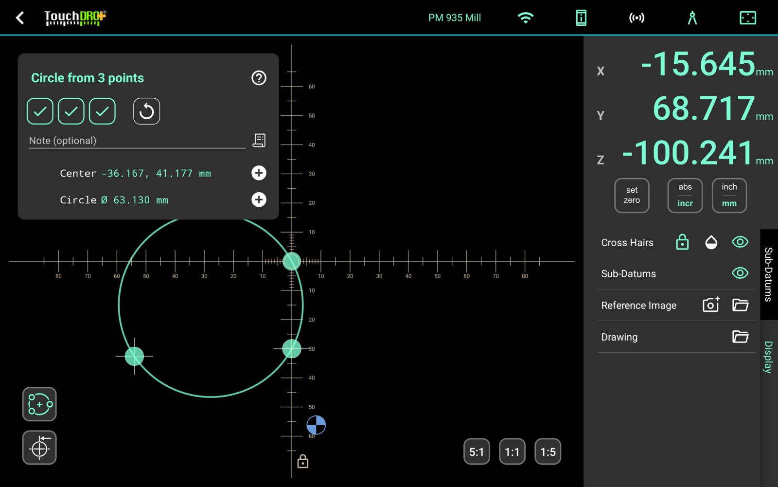
The note field and the log button beside it file the measurement in the inspection log, with your note and a sequence number.
The Inspection Log
The log is the record of what you measured, kept per workspace. Saving a result puts a coordinate into sub-datum memory for the machine to use; logging it keeps the reading, the points behind it and your note, so the measurement can be read back or handed to somebody else.
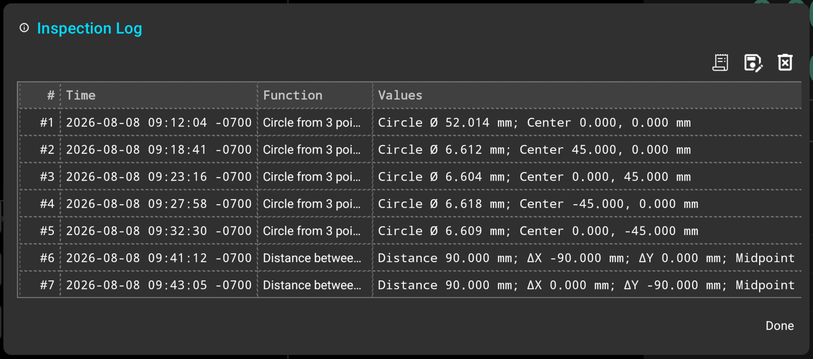
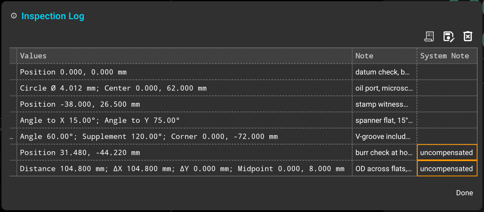
To open it, tap the log button. Each row carries its sequence number, a timestamp, the function, the values it produced, your note and a system note.
The system note is TouchDRO's own account of how a reading was taken, and it is kept apart from your note rather than merged into it. A row measured with an uncompensated tip carries "uncompensated" there, outlined in amber, so a reading that needs a caveat still carries one after you have forgotten typing it.
Exporting the Log
TouchDRO writes the log out in two formats. Both carry the same measurements, and the file name records the workspace, the machine profile and the time of the export, so a file still says where it came from once it is off the tablet.
The text file is laid out for reading. Each measurement is a block with its number and timestamp, the result rows as the card showed them, your note, and the points the function was given:
#8  2026-08-08 09:45:39 -0700
Distance between 2 points
  Distance    63.640 mm
  ΔX          -45.000 mm
  ΔY          45.000 mm
  Midpoint    22.500, 22.500 mm
  Note: adjacent hole spacing
  P1 sub-datum  45.000, 0.000 mm
  P2 sub-datum  0.000, 45.000 mm
The CSV file is laid out for a spreadsheet. It carries one row per measurement and one column per result any function can produce, so a column that doesn't apply is left empty: a "Circle from 3 points" row fills "Diameter", "Center X" and "Center Y" and leaves the angle and distance columns blank. Units are stated in the column headings rather than beside each value, which is what lets you sort or subtract a column without stripping text out of it first.
"Seq","Timestamp","Function","Points","Note","System Note","Diameter (mm)","Center X (mm)","Center Y (mm)",
"Distance (mm)","DX (mm)","DY (mm)","Midpoint X (mm)","Midpoint Y (mm)","Angle (°)","Supplement (°)",
"Corner X (mm)","Corner Y (mm)","Angle to X (°)","Angle to Y (°)","Position X (mm)","Position Y (mm)"
Both formats record where each point came from, marking it as taken with the probe, entered from an existing sub-datum, or captured at the current position.