
Align Measurement Axes
Inspecting a part usually starts with clamping it square, and on a casting, a weldment or a part that arrived from somebody else, indicating it in can take longer than the measurement does. On an optical comparator, you solve this by turning the stage until the part's own datum edge lines up with the reticle, and then measuring from there.
The "Align Measurement Axes" function does the same thing on your mill. It turns the X and Y readouts to match the part, so you can measure a part clamped at an angle without indicating it in: square the readouts to an edge and work from the part's own datums.
You run into the same thing when reverse engineering a part you want to copy. Clamp it in the vise to pick up its hole pattern and it sits however it lands in the jaws, at some angle nobody chose. Square the readouts to one of its edges before you start, and every coordinate the measuring functions capture comes out in the part's own frame, ready to export as a drawing and draw from.
Squaring the Readouts Instead of the Part
The function is part of measurement mode, and its button sits on the graphical view beside the log button. There is a practical reason it lives there: a manual mill can only feed along its own axes, so a readout turned away from them cannot be driven to zero one handwheel at a time. To machine a part that sits at an angle, use the "Rotate Part" function, which turns the stored geometry instead and leaves the readouts in machine position.
Work in the order a comparator operator does: datum first, then align. Set your zero on the feature the drawing measures from, using the "Indicate Workpiece" function or a captured point, and then turn the readouts to the part's edge. The rotation happens about that zero, so the origin you just set stays the origin.
From there every coordinate you read, and every point the measuring functions capture, is stated in the part's frame rather than the machine's.
The Align Measurement Axes Dialog
To open the dialog, tap the "Align Measurement Axes" button. The illustration on the left of the dialog shows what turns: the part stays where it is and the X axis swings to meet it, with a positive angle α running counter-clockwise from the machine's own X.
The "Angle source" row across the top picks where the angle comes from, and the rest of the dialog changes to match.
Measured
"Measured" works the angle out from two points along the part's edge, which is the setting to reach for on a part with no stated angle. Each point can be the current position, the origin, or a custom point, and "Custom" offers both a picker for a saved sub-datum and typed coordinates, so an edge you captured earlier can serve without touching the part again.
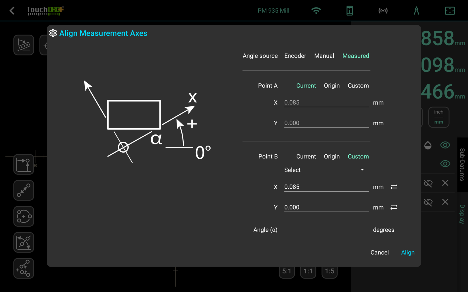
Spread the two points as far along the edge as the part allows. The angle is only as good as the distance between them: the error in the angle is roughly the error in a point divided by their separation, so a pair close together gives a number that looks precise and is not.
Encoder
"Encoder" reads the angle live from the machine's angular axis, for a part on a rotary table or a tilting fixture. This is the comparator's rotating stage: turn the table until the part's edge runs true, and the readouts follow it.
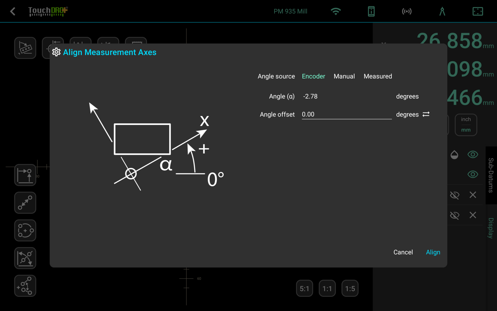
The angle the axis reports is rarely zero where you want your reference to be. Set the fixture to the orientation you want to count from and tap the sync button beside "Angle offset": TouchDRO stores the current reading as the offset, so "Angle (α)" reads 0.00 there and counts from the part afterwards.
Manual
"Manual" takes a typed angle, for when the print states it and you only need the readouts to agree.
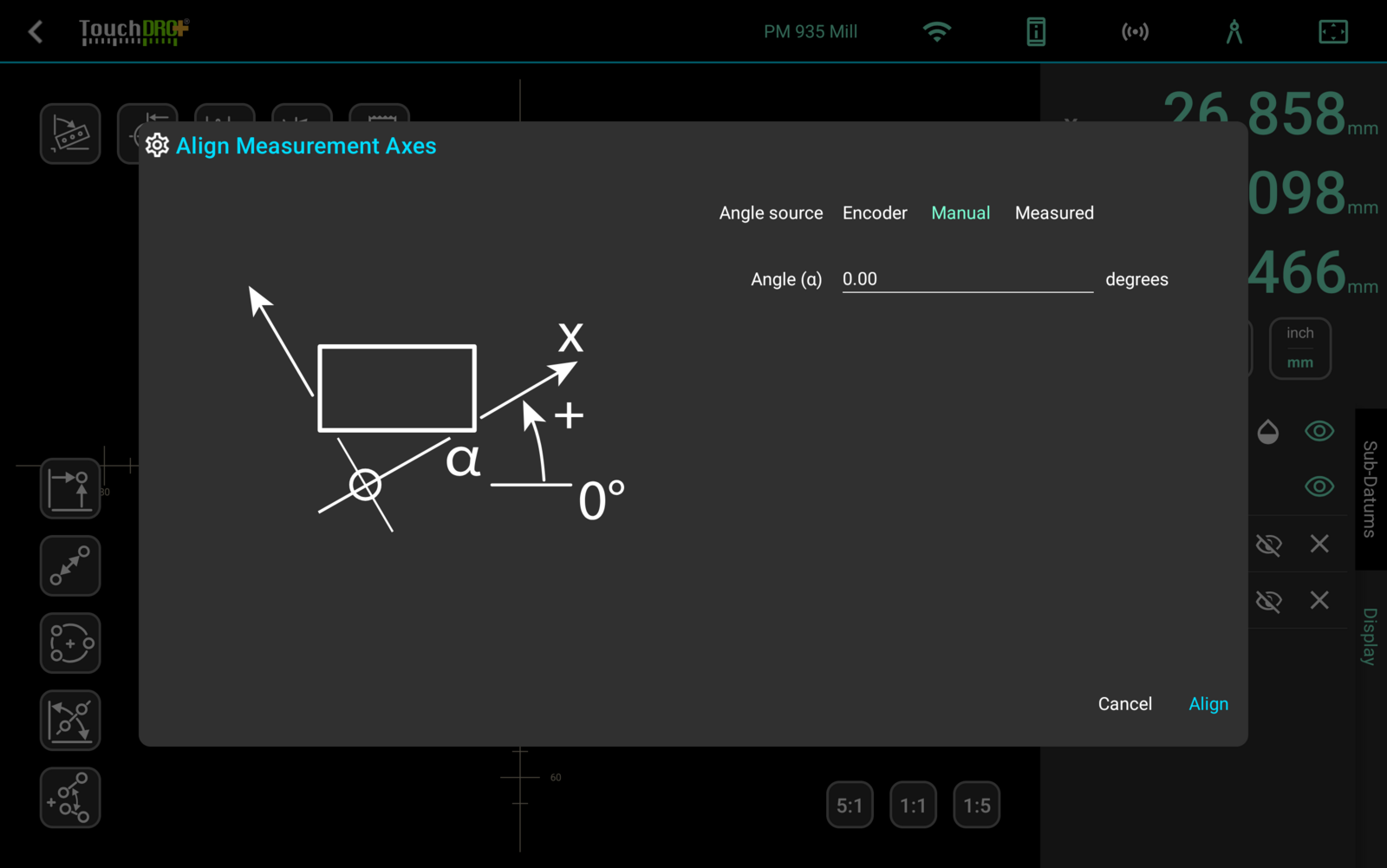
Tap "Align" to apply, and the readouts take up the angle.
Typed and Picked Coordinates
The coordinates in a point field are readout numbers. They name the spot where X and Y would show those figures, and TouchDRO works back from them to the machine position, undoing the alignment on the way.
That is what keeps the dialog self-consistent. Open an alignment that is already in force, read the two points off the rows, type them straight back in, and the angle comes out the same.
When you pick a sub-datum from the list, TouchDRO fills the fields with where that feature sits now, with any rotation already accounted for. If you then nudge one ordinate by hand, TouchDRO reads the edited figure in the same frame, so a nudge is just a nudge.
Working With a Turned Frame
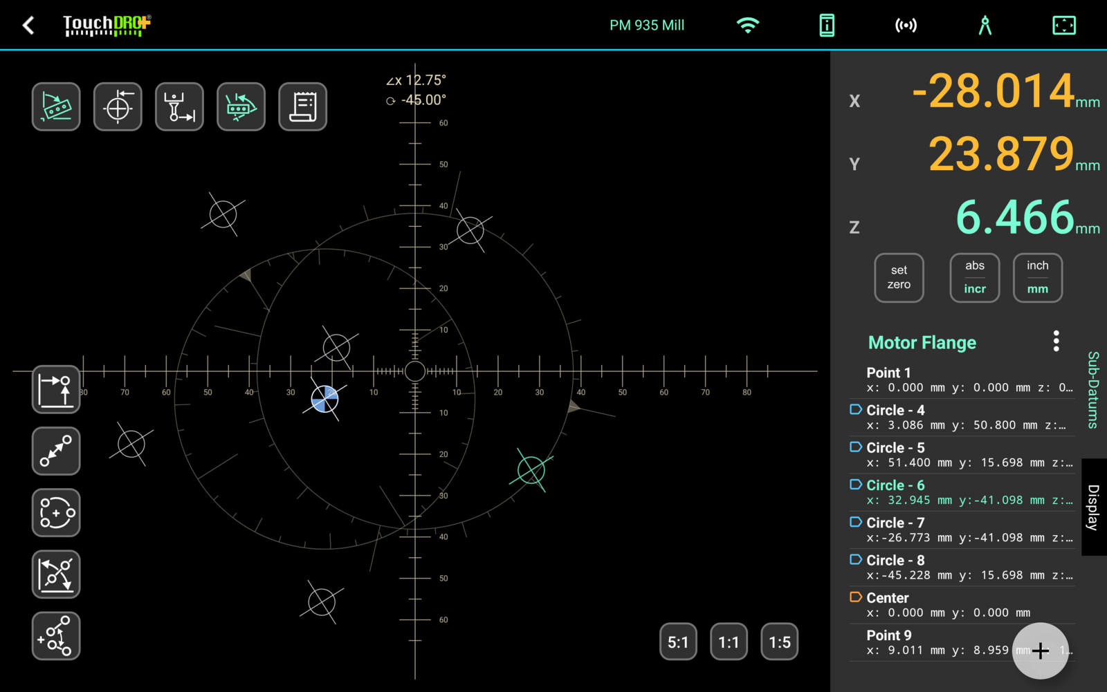
The X and Y readouts are drawn in amber while the frame is turned, the same amber the readouts wear whenever they report something other than raw machine position. Z stays in the normal color, since the rotation happens in the X/Y plane.
Your stored work stays where it is. Sub-datums, the drawing and the reference image keep their coordinates, and the rotation applies to what the readouts report rather than to what you have saved.
TouchDRO reports the angle at the top center of the canvas, marked "∠x" for the axis it turns, and draws a protractor ring for it. The ring's ticks point outwards, zero sits at three o'clock, and a positive angle runs counter-clockwise from it, which is the convention the dialog's illustration uses.
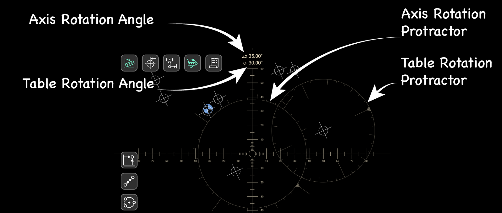
Clearing the Angle
To take the angle off, open the dialog and tap "Clear". A long-press on the button does the same, after a confirmation. The readouts return to the machine's own axes, and the label and the ring come off the canvas.
Squaring Up to a Part
A part with a straight edge to work from goes like this. The order matters: the rotation happens about the origin, so the origin comes first.
- Clamp the part however it sits, with the edge you will measure from reachable
- Set the origin on the feature the drawing measures from, with the "Indicate Workpiece" function or a captured point
- Open the dialog and choose "Measured"
- Set "Point A" to a spot at one end of the datum edge and "Point B" to a spot at the other, taking each with "Current" as you reach it. "Angle (α)" fills in as the pair resolves
- Tap "Align". X and Y turn amber, and the protractor ring appears on the canvas
From here every reading is in the part's frame. Drive along the part's edge and Y holds still while X counts, which is what tells you the frame is square to it.
When the print states the angle, you can skip most of that: set the origin, choose "Manual", type the angle, and align. On a rotary table you can skip it too, with "Encoder" reading the table's own angle.