Programming Lathe Tool Offsets
Programming (adding) tool offsets to the Tool Offset Memory in TouchDRO is very straightforward and intuitive. The purpose of this article is to illustrate a few common examples so you can use this feature to speed up your turning process and reduce potential for mistakes.
Important Considerations
Tool Offset Memory relies on the ability to re-insert a given tool without altering its relative position. This means the following:
- Your lathe should be equipped with a repeatable tool post and the cutters should be mounted into dedicated holders.
- Any time you remove the tool from its holder or regrind the edge, you should re-measure and update the offsets for this tool.
- The tool post angle must not change between when you program the tool and when you use it or the offsets will be invalid.
- If the compound slide position or angle changes you will need to re-indicated the workpiece (unless your compound slide position is tracked by TouchDRO).
Overview
Before you start entering tool offsets into the Tool Offset Memory, let's take a quick look at the process.
The tool offsets are defined in relation to a tool that is considered to have 0 offset. We will call it the "master" tool. A master tool it's just an arbitrary cutter that we will choose as a starting point. For each subsequent tool we will measure the offset (difference in position) between its cutting point and the master and store those distances in TouchDRO memory. The most challenging (and important) part of the process is the accurate measurement of the offsets; data entry is very simple and TouchDRO [mostly] takes care of the involved math.
Preparation
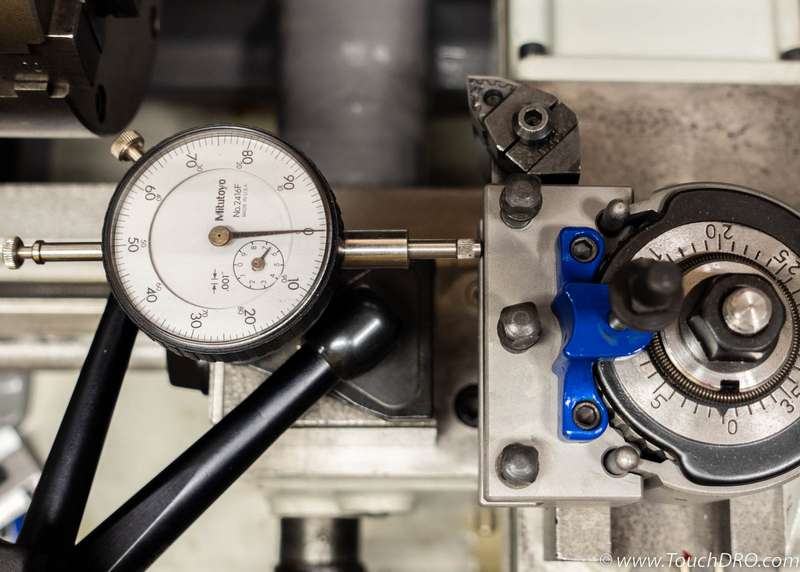
Before entering tool offsets into the Tool Offset Memory we need to prepare the cutters and the machine. Start by checking that the cutters are all mounted securely into their tool holders and their cutting edges are at the right height in relation to the centerline of the spindle.
Set Tool Post Angle
It's extremely important that the angle of the tols post is set accurately when using the Tool Offset Memory. In most situations the tool post should be set to be precisely square/parallel to the machine's axes of travel. Unless you have replaced your compound slide with a solid tool post, you can pick a dedicated tool holder with a straight side and sweep it with an indicator to ensure that the angle is set correctly.
Pick a Master Tool
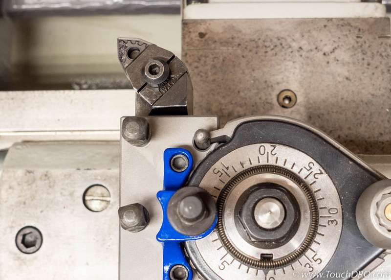
A master is simply a tool that we designate as having no offsets. Although any tool can be chosen as a master, it's more convenient in the long run to pick an indexable tool that can do facing and turing cuts.
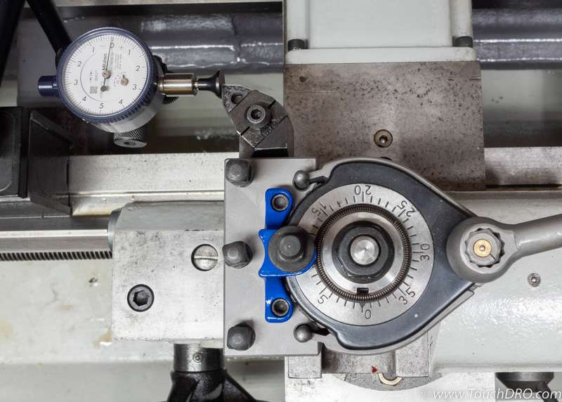
In this example we will use the holder shown below since it's a tool that is almost never removed from its holder and uses indexable inserts that can turn to the shoulder (and will therefore be easy to use to establish a surface if needed).
Tool Offset Entry
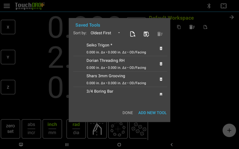
Let's start by entering stub records for the tools we will be programming:
- Bring up the "Tool Library" window
- For each tool do the following:
- Press the "Add New Tool" button
- Enter the name that will identify the tool
- Optionally, enter the description
- Ignore the offsets for now (they will default to 0)
- Press the "Add Tool" button in the lower-right corner
Your end result will look something like the screenshot below. Note that we added an asterisk (*) to the first tool as a reminder that this will be our starting point
X Offsets
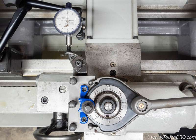
Now we need to establish the position of the "master" tool. In this case we will use a plunger type-indicator to do it one axis at a time, starting with the X axis as follows:
- Mount the indicator on the machine so its axis of travel is parallel to the cross slide as shown in the picture below. Be sure do not move/disturb it until all X offsets are entered
- Touch off the master tool until the indicator reads 0
- Make sure that TouchDRO is in absolute coordinate system and is showing radius (not diameter) reading
- Without moving the cross slide, press and hold "Set Zero" for the X axis; this will set the absolute position to 0.
- Bring up the "Tool Library" dialog
- For each tool, except the "master":
- Click on the relevant tool record in the list to bring up the "Edit Tool" dialog
- Mount the tool into the tool post
- Touch off the tip of the tool until the indicator reads 0 again
- Press the "Synchronize" icon button next to the X Offset field.
- Press the "Save" button to save the offset and close the dialog
Once you do these steps for all tools, let's verify that the process worked:
- Mount the master tool into the tool post
- Exit back to the main DRO screen
- Move the cross slide until the indicator reads 0
- Press and hold the "Zero Set" button for the X axis
- Mount a different tool into the tool post
- Bring up the "Set Tool Offset" dialog
- Select the mounted tool from the dropdown
- Press the "Set Offset" button
- Move the cross slide until the indicator reads 0
If everything worked, the X readout should be showing 0.000; Z readout should not have changed, since we haven't entered Z offsets. Press and hold the "Set Tool Offset" button to clear the offsets before moving to the next step.
Z Offsets
The process of entering Z offsets is very similar:
- Rotate the indicator so it's axis of travel is now parallel with the spindle, as shown below
- Mount the master tool into the tool post
- Touch off the tip of the cutter until the indicator reads 0
- Press and hold the "Set Zero" button for the Z axis without moving the cross slide
- Bring up the "Tool Library" dialog
- For each tool (except the "master"):
- Click on the relevant tool record in the list to bring up the "Edit Tool" dialog
- Mount the tool into the tool post
- Touch off the tip of the tool until the indicator reads 0 again
- Press the "Synchronize" icon button next to the Z Offset field.
- Press the "Save" button to save the offset and close the dialog
Once Z Offsets for all tools are entered, verify that the process worked as described in the section above (except for the Z axis).
Other Situations
The process described above works for most basic tools but you might run into a situation where measuring the offset this way is not feasible. In those situations you might need to use a more manual approach, so let's cover some of them:
Master Tool Not Available
In the previous steps we used a master tool to define other tools. In some cases using a master tool might not be possible for various reasons. Fortunately, it's very easy to use any other tool that is already in the Tool Offset Memory. The process is similar to the above, but includes a few extra steps:
- Mount the existing tool into the tool holder
- Using the "Set Offset" command, select the tool from the dropdown list and apply the offsets (X and/or Z readouts should be amber)
- Touch off the tip of the tool to the indicator until it reads 0
- Press and hold the "Set Zero" button for the relevant axis; the readout now shows zero
- Press and hold the "Set Offset" button to clear the active tool offsets
At this point the axis will show some position, which is the offset of the current (existing) tool in relation to the master. In essence, we "reverse engineered" the position of the master tool. From this point the process for setting other tools is the same as step #6 in the examples above.
Different Tool Post Angle is Required
This is a common situation. When using a Multifix-type tool post, you simply insert the new tool at the desired angle and enter the offsets as before. With other tools posts the process is almost identical to the basic examples above, but before step 6 you will need to rotate the tool post.
To avoid future mistakes, you can include the angle in the name of the tool so they are easy to spot.
Cutter With Multiple Cutting Edges
When using a cutter that has more than one cutting point. This might be a tool holder that holds square inserts such that two vertices can be used, etc. In such a case you would simply treat them as separate tools and have multiple entries in the library.
One of the Offsets Is Not Fixed
This situation might arise when the tool needs to be repositioned between different jobs. For example, you might have a boring bar or a cutoff tool and want to change the stick out to maintain maximum rigidity. In this case you can enter offset only for the axis that remains fixed and leave the other as 0.
The catch is that you will need to indicate the undefined axis before using the tool, and then after switching to a new tool, re-indicate it on that tool to re-establish the coordinate system.
Can't Directly Measure Offset
There might be cases when you can't directly compare the position of the new tool to the master tool.Let's consider a situation where you want to add a boring bar to the Tool Offset Memory.
In such a situation you will need to do some basic math to calculate one of the offsets. Let's assume that your master is a right handed tool and so is your boring bar. In this situation the Z axis is easy (simply follow the basic process above) but for the X axis you will need to do some basic math. The process can be as follows:
- Take a light turning cut with your master tool
- Switch TouchDRO to radius display
- Without retracting the cross slide, press and hold the "Set Zero" for the X axis. This will set the readout to 0
- Mount the boring bar into the tool post and take a light boring cut
- Without retracting the cross slide, measure the wall thickness (or calculate it by subtracting the ID from the OD and dividing the result in half)
- Press the X axis readout to bring up the "Set X Axis Absolute Dimension" dialog
- Add the OD from step 5 to the current reading. This field accepts arithmetic operations, so you can simply add
"+
" (without quotes) after the pre-filled number. - Bring up the edit dialog for the boring bar (from the Tool Library) and use the sync button to set X axis offset
- Save the change by tapping the "Save" button
- Open the "Set Tool Offset" dialog, select the newly added boring bar from the dropdown list and press "Set Tool Offset"
- Switch TouchDRO to diameter mode.If everything went right, the reading for X axis should be the same as the diameter you measured in step 7
