
Measurement Mode
A milling machine equipped with 5μm DRO scales and a rigid cast frame can easily be the most precise measuring instrument in a small shop. With some care, you can position the table to within a few ten-thousandths of an inch, while measuring parts that span tens of inches.
On its own, though, a DRO only tells you where the table is. Measuring a part also takes something that can tell you precisely when you are over a feature, and a way to turn the positions you capture into the dimension you are actually after. In measurement mode, with an inexpensive digital microscope or a touch probe, you can use TouchDRO for basic inspection work, or to pick up the coordinates of features that are difficult to reach with calipers or micrometers.
This is useful in two situations in particular. You can check the part you just made without unclamping it and carrying it to a surface plate. You can also pick up the dimensions of a part you didn't make, one feature at a time, and finish with a set of coordinates you can draw from.
What You Can Do With It
Measurement mode provides a convenient way to digitize an existing part, to pick up features you can't measure directly with calipers or a micrometer, and to inspect work you have already finished.
You can use it in a few different ways, and they build on each other:
- Indicate a part with a camera or an inexpensive digital microscope, the same way you would with a 2D touch probe mounted off the spindle
- Locate coordinates directly with that same microscope and add them to sub-datum memory as you go
- Use the measuring functions for the features you can't put crosshairs on directly - the center of a partial bore, the point where two lines intersect, the angle between them
- Inspect a finished part and log what you measured
For instance, when the corner between two sides is rounded or damaged, you can indicate the two sides and have TouchDRO calculate the point where they would have met. The sides don't need to meet at 90 degrees.
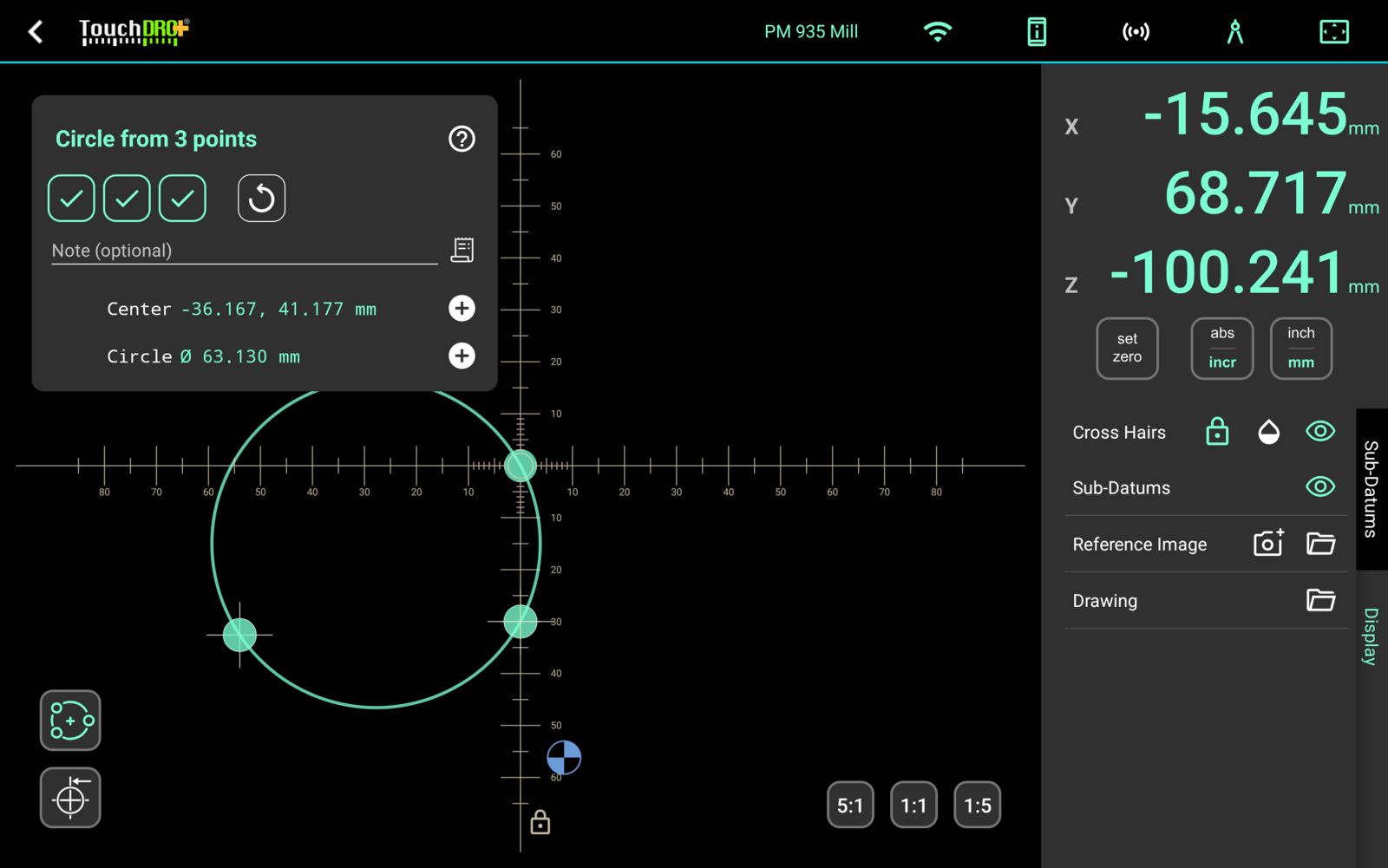
Three points anywhere along an arc are enough to give you the center and the diameter of the circle that arc belongs to, so a bore broken by a slot, or one that runs off the edge of the part, is still measurable.
Each function, and what it does with the points you give it, is described in the "Measurement Functions" page.
Entering Measurement Mode
Measurement mode is part of TouchDRO Plus and runs on milling machine profiles. Without Plus, or on a lathe profile, the toggle button stays in the application header but is locked and dimmed.
To switch between cutting and measuring, tap the drafting compass button in the application header. It sits second from the end, next to the graphical view button.
The Measurement Display
TouchDRO draws measurement mode in mint, and the graphical view's crosshairs in a bone color, so a glance at the screen is enough to tell you which mode you are working in.
The work is split across the two screens you already use. The main readout carries the functions that set a measurement up, and the graphical view carries the ones that take it.
On the main readout, the function strip along the bottom holds the "Indicate Workpiece" function, "Head Tilt Compensation", and the "Reference instrument" function. The three functions that describe a cutting tool are absent, since in measurement mode there is no cutting tool.
Start with the "Indicate Workpiece" function. It sets the origin your measurements are referred to, and every coordinate you capture afterwards is stated from there.
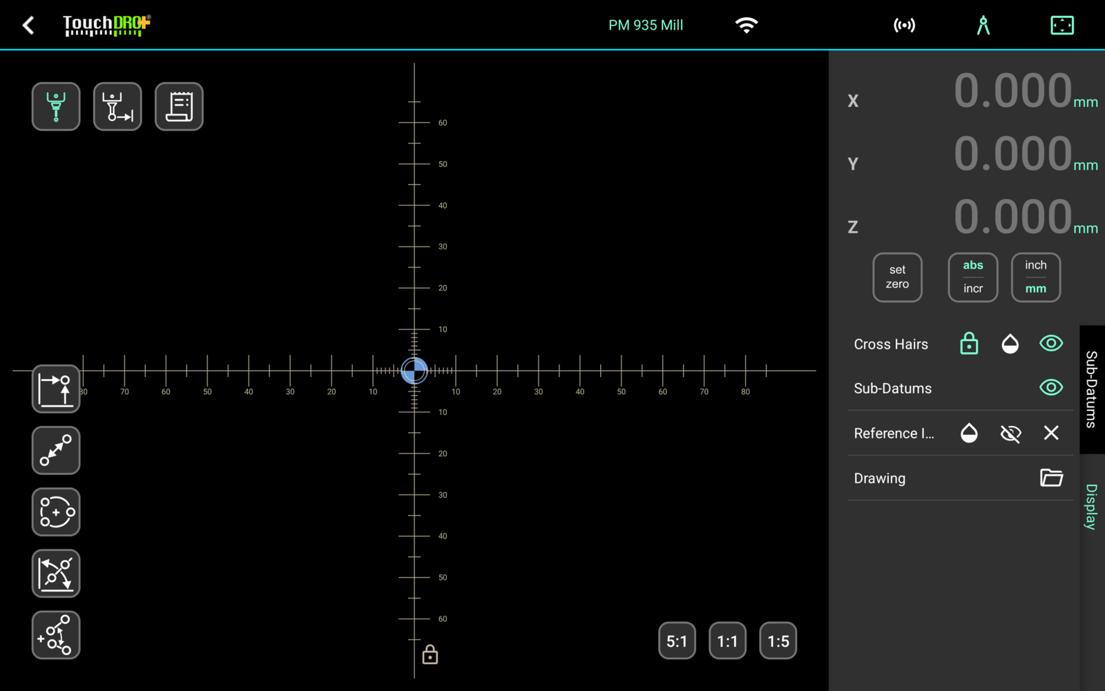
The measuring functions themselves run down the left edge of the graphical view, with a few general functions, including the log button, along the top. To start a measurement, tap one of them. TouchDRO will hide the rest of the strip and show a card that walks you through the points that function needs, then draw the result on the canvas once it has enough of them.
The Reference Instrument
It's often convenient to mount the measuring instrument off axis. A digital microscope or an industrial vision camera, for instance, is much easier to mount to the side of the mill's head than on the spindle centerline.
The offsets are stored in the instrument's probe profile. Pick that profile in the "Reference instrument" function and TouchDRO will compensate for the offsets as it goes. In other words, the features and sub-datums you capture will still be correct in relation to the spindle when you switch back to cutting.
To choose an instrument, tap the "Reference instrument" button in the function strip. This will open the "Reference instrument" dialog.
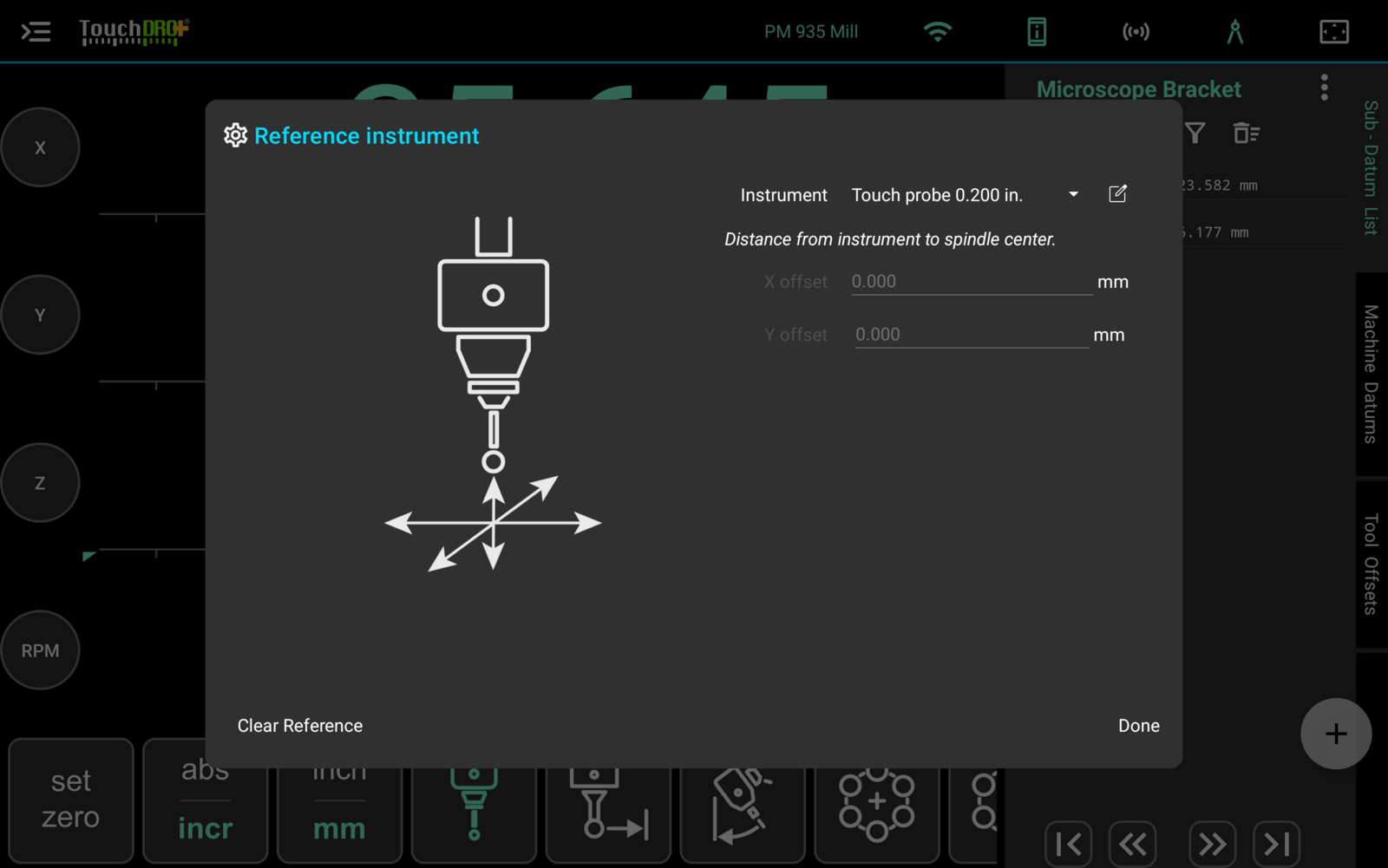
The "Instrument" selector lists the "Camera / microscope" and "Touch probe" profiles stored in the "Probe Library", each with its tip diameter and trigger port. The last entry, "New profile…", adds an instrument to the Probe Library, and the edit shortcut next to the selector will open the selected profile for editing. Profiles themselves are covered on the probe profiles page.
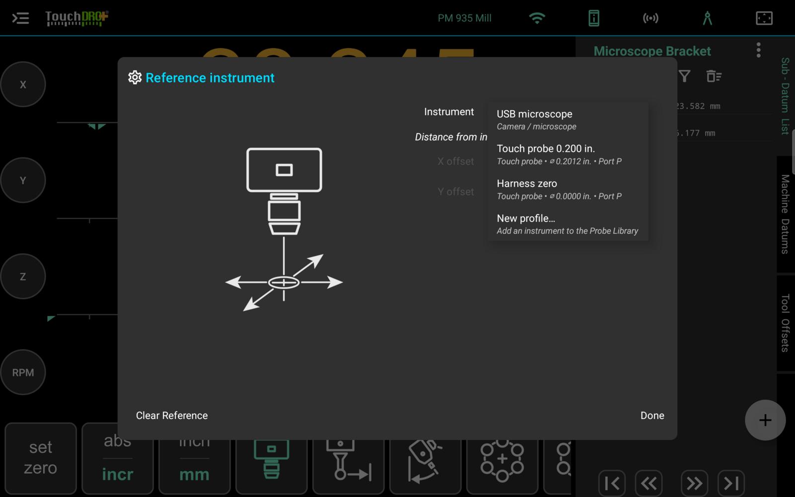
Underneath the selector, "X offset" and "Y offset" hold the distance from the instrument to the spindle center, taken from the profile you picked. A microscope bolted beside the head carries a real offset in both axes. A touch probe held in the spindle sits on the spindle axis, so both of its offsets are zero.
Until you pick an instrument, the selector will read "No instrument selected", with the line "Readouts refer to the spindle axis" below it.
The button's icon follows your choice, so it will show a microscope for a camera and a probe glyph for a probe. To clear the reference and send your readouts back to the spindle axis, tap "Clear Reference" at the bottom of the dialog, or long-press the button in the function strip. TouchDRO will ask you to confirm in the "Clear Reference Instrument" dialog.
Amber Readouts
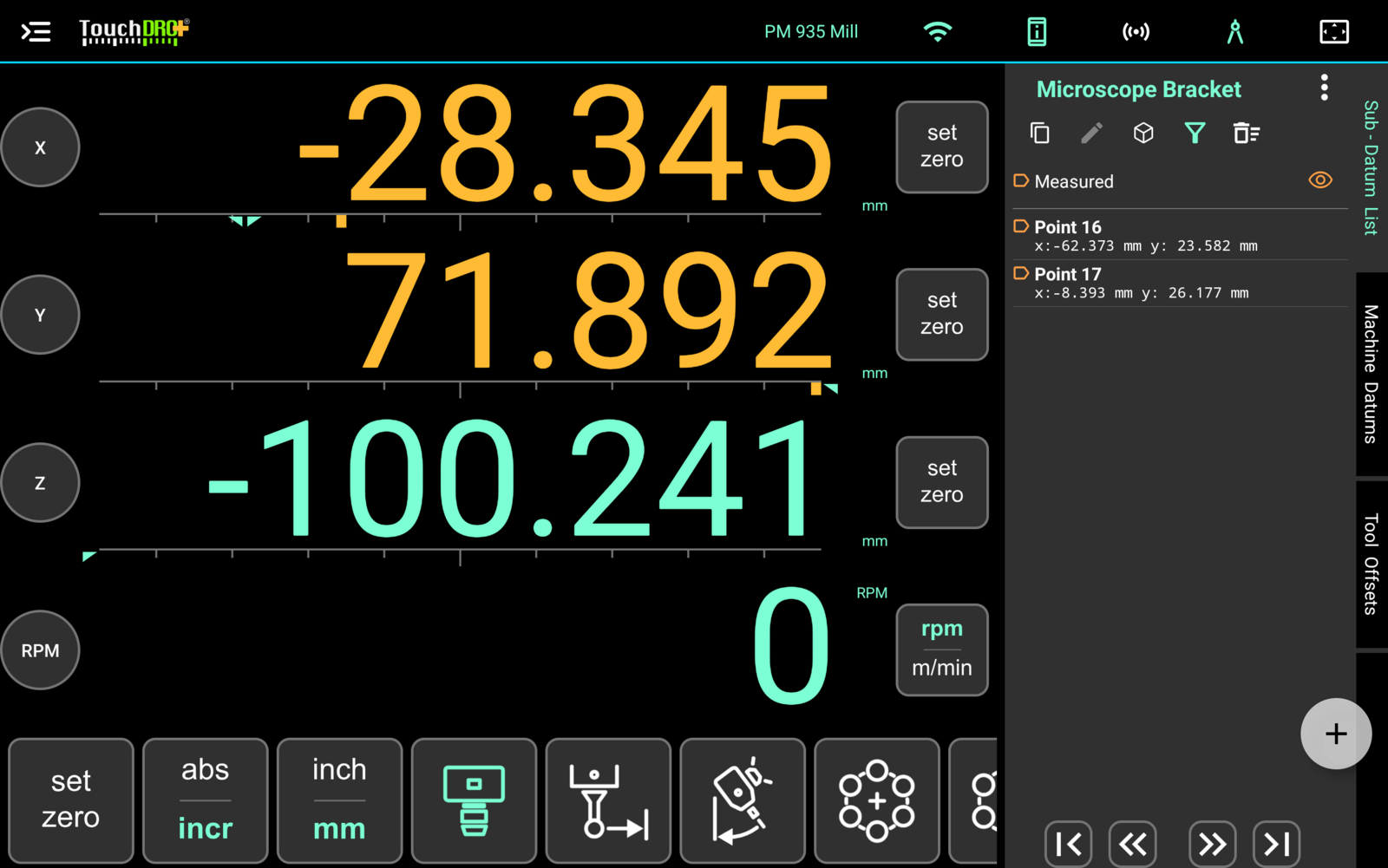
An axis drawn in amber is carrying an offset. The color follows the offset rather than the instrument, so an axis with a non-zero offset is drawn in amber whatever is mounted, and an axis without one is not.
What you see therefore depends on the profile you picked. A microscope mounted beside the head carries an offset in X and Y, so both are drawn in amber while Z stays mint, as in Fig. 2. An instrument whose offsets are both zero leaves every axis mint.