
Machining a Part from a Photo
Making a mating part for something that already exists is one of the most common jobs in a small shop. The box below is a typical case: a cast enclosure that needs a cover plate, with screw holes and clearance holes that have to land where the box says they land. There is no drawing to work from.
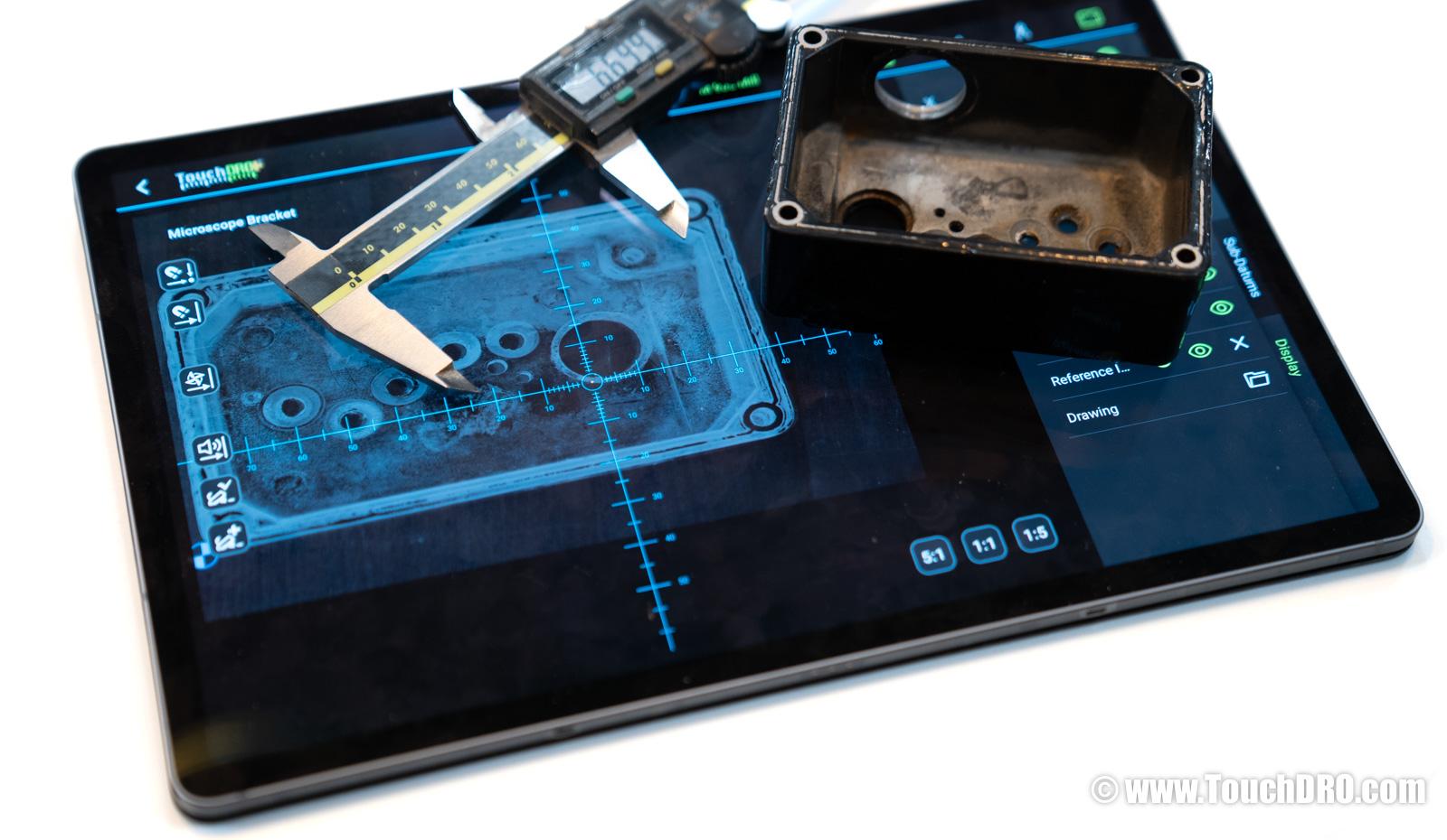
The traditional way is to measure the box, coat the blank with Dykem, and lay the holes out with a scribe and a caliper. That works, but transferring a photo into TouchDRO gets very good results much faster, and the layout can't rub off. Bluing disappears under chips and cutting oil; the image on the screen stays crisp to the last hole. This guide walks through the whole job, from the photo to the drilled cover.
A cover like this only needs the holes to clear the screws, and the photo path delivers that comfortably. It is not a precision measuring tool, and it works on flat parts only; for reverse engineering to real tolerances, the probing workflows described in the "Edge Finder (Indicate Workpiece) Function" guide are the better fit.
Taking the Photo
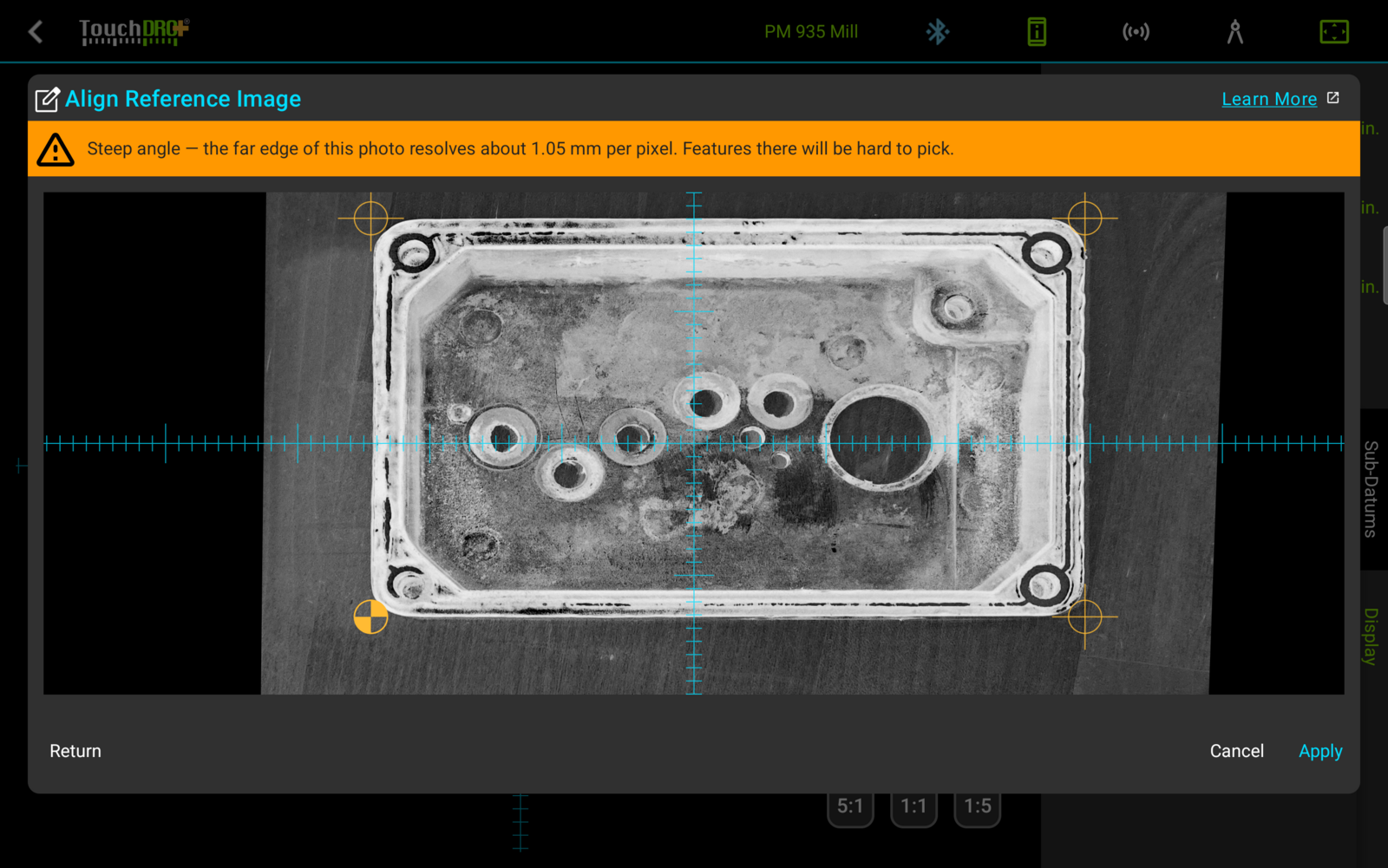
Put the box on a flat surface, open face up, and photograph it from directly above with the tablet's camera. Fill the frame with the part, and keep the camera as square to the face as practical. TouchDRO will correct a moderate perspective tilt very well, but a photo taken at a steep angle leaves the far edge of the part with too few pixels to pick features from.
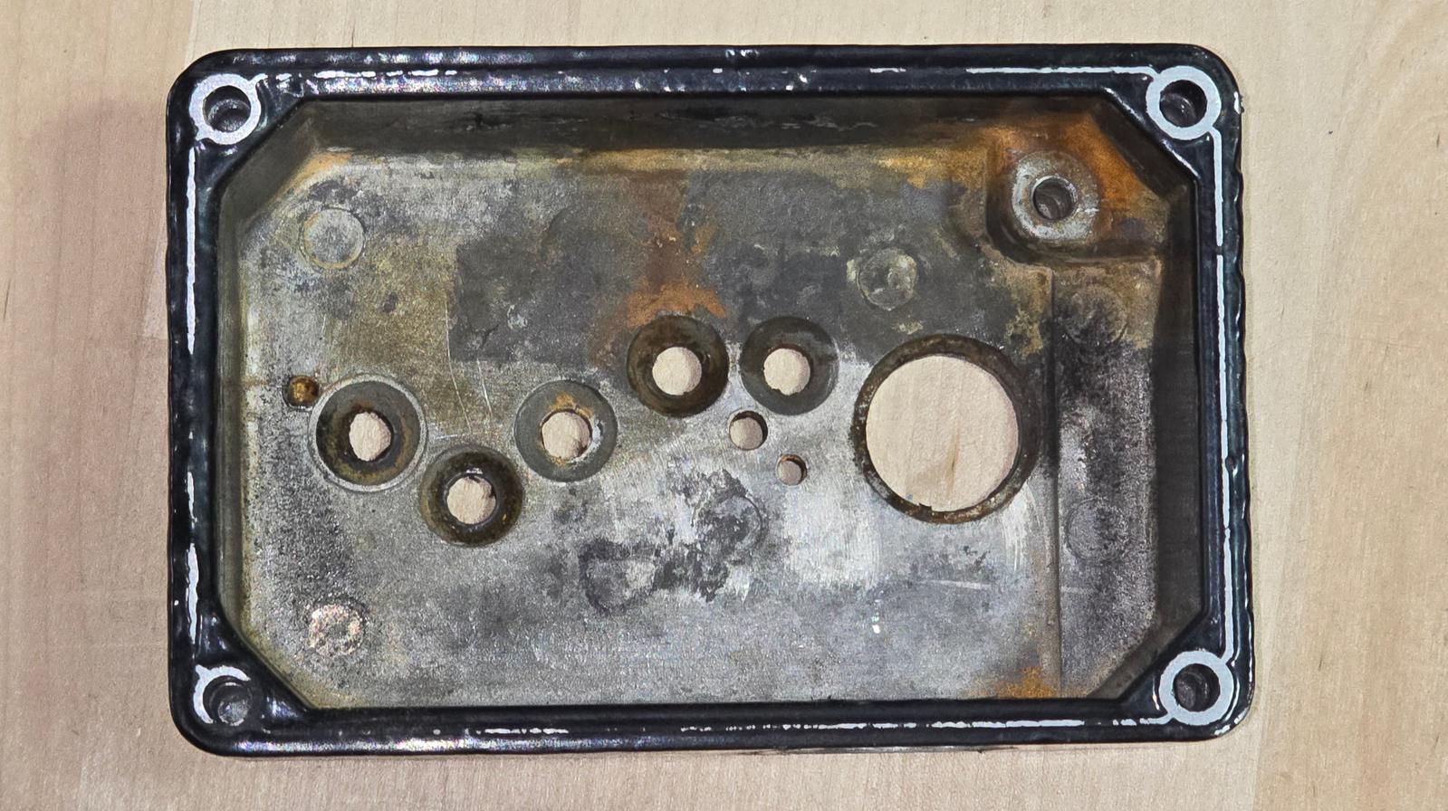
The face being photographed has to be flat. The perspective correction maps one plane onto the machine's coordinates; features at other heights shift by different amounts in the photo, so a multi-level part won't line up at every level at once. For this box, the mounting flange is the reference plane. Everything on it, the screw bosses and the outline, can be trusted; the bottom of the box can't.
The only measuring in the whole job happens now: measure the two outside dimensions of the flange with a caliper. This box comes out at 120.0 mm by 69.0 mm. Those two numbers, plus the photo, are everything TouchDRO needs.
Loading the Photo into TouchDRO
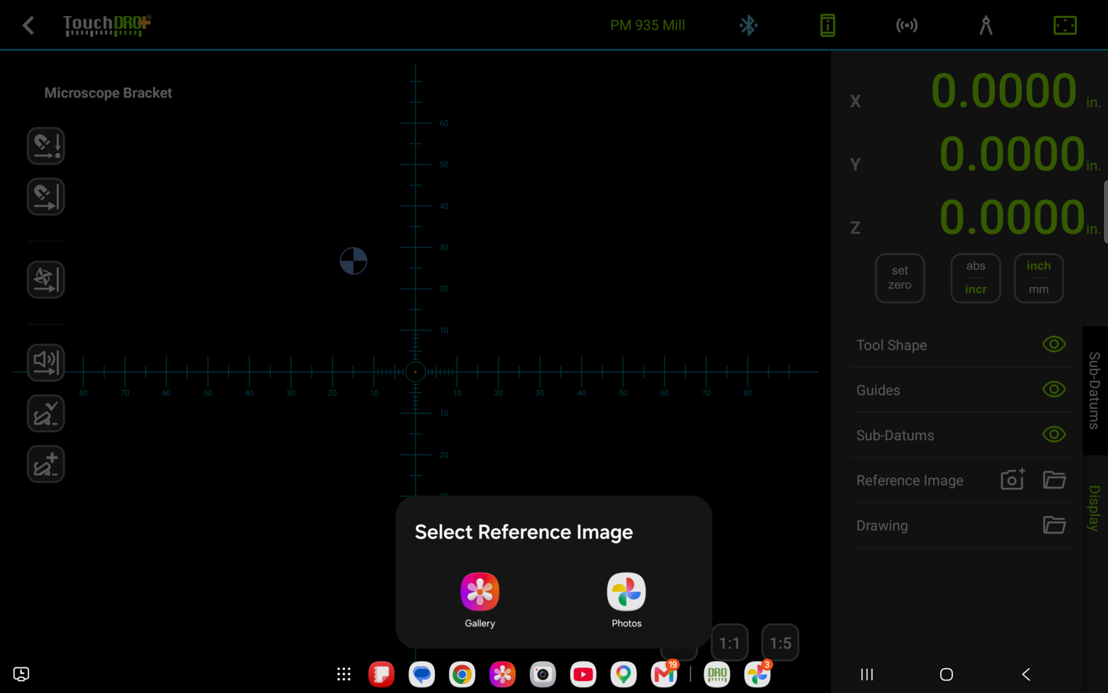
Mount the cover blank in the machine and set the absolute origin at the corner that will mate with the box's lower-left corner. Then open the "Display" panel in the graphical view and load the photo. The camera button on the "Reference Image" row takes a new photo directly, and the folder button picks one already on the tablet.
The photo opens in the "Align Reference Image" dialog. Take care of orientation and appearance before placing any points, since the rotate and flip buttons lock once the first reference point is set. This photo was taken in portrait, so the first tap is the rotate-left button. Then the palette button removes the color and the droplet inverts the image: a gray casting on brown plywood turns into a crisp white-on-black outline that reads like a blueprint, which is what the rest of the screenshots on this page show.
Aligning the Photo to the Machine
The four corners of the flange are the reference points, and their coordinates come from the two caliper measurements: the lower-left corner is 0, 0, the lower-right is 120, 0, the upper-right is 120, 69, and the upper-left is 0, 69.
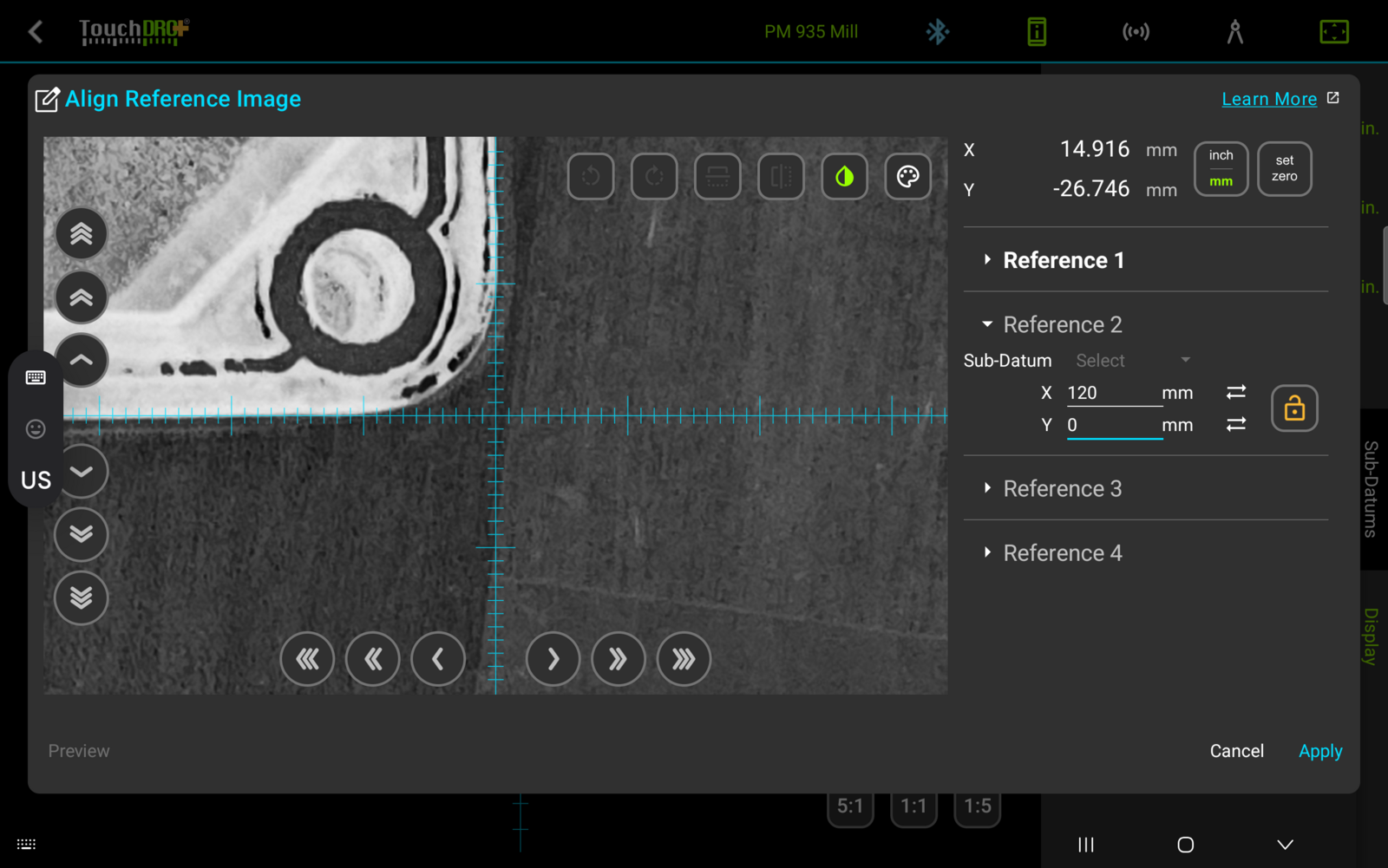
Zoom in on the first corner and walk the image onto the crosshairs with the chevron buttons along the left and bottom edges of the preview. The single, double, and triple chevrons move the image by 1, 10, and 100 pixels per tap. There is no need to nudge pixels with careful finger gestures; get close with a drag, then let the buttons do the last approach. Enter 0 and 0 into the "Reference 1" fields and tap the lock button.
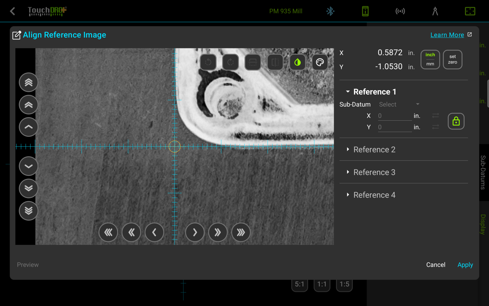
Repeat for the remaining corners: pan to each one, walk it onto the crosshairs, enter its coordinate, and lock it. Four points let TouchDRO undo the perspective of a hand-held photo; the residual tilt of the camera comes out in this step, which is why the photo only had to be roughly square.
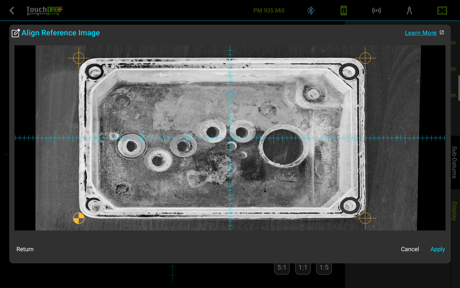
With all four points locked, tap "Preview". The corrected image is shown straightened and to scale, with the four reference marks on it. "Return" goes back if a point needs adjustment, and "Apply" sets the photo as the workspace background.
Working from the Photo
After "Apply", the photo sits in the graphical view at true scale, aligned to the machine. The crosshairs are the spindle, and every feature of the box is where the readouts say it is. Drilling the cover is now a matter of driving the crosshairs onto each hole in the photo, checking the readout looks sensible, and drilling. The zero point, the hole spacing, and the odd out-of-pattern hole all come from the image; the only numbers that were ever typed in are the two caliper measurements.
One last touch: tap the half-opacity button on the "Reference Image" row to dim the photo to 50 percent. The part stays perfectly readable, and the crosshairs and sub-datums stand out against it instead of fighting the photo for attention.
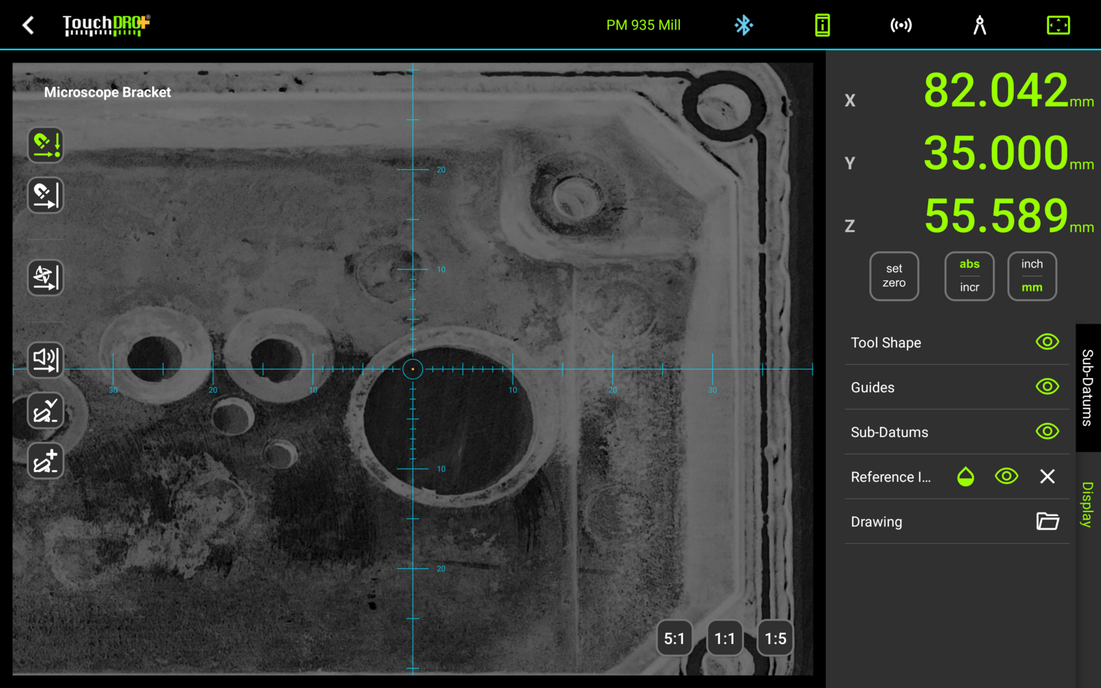
The eye button on the same row hides the photo when it has done its job, and the clear button removes it when the cover comes off the machine. The dialog's controls, and the rest of the reference image function, are covered in the "Reference Image Overlay" guide.
If the part ever exists as a CAD file, skip the camera entirely: the "Machining to a CAD Drawing" guide covers the same kind of job with a drawing instead of a photo, at true scale with no reference points needed.