
Machining to a CAD Drawing
A big share of the mistakes made on a manual machine happen while reading the drawing, not while cutting metal. Every feature means looking away from the machine, finding the next dimension, doing the coordinate math, and checking whether that hole is already drilled. The more complicated the part, the easier it is to lose your place. For example, the fixture plate below has two different hole sizes: some are reamed to 6 mm, and the others are threaded. It's easy to accidentally drill a hole to the wrong diameter, and with a drawing full of identical-looking circles, easy not to notice until the tap has nothing to bite on.

Drawing import removes most of that work. A CAD drawing imported into TouchDRO is displayed at true scale in the graphical view, and as the machine moves, the crosshairs move across the drawing, so it is immediately obvious where you are and what comes next. Complex contours become virtual layout lines, and hole centers, arc centers, and corners can be stored as sub-datums for one-tap navigation.
You can import a DXF file from any CAD program that exports one. If you draw in SnapCAD, you can also export the drawing straight to TouchDRO's own format, which is the simplest path because TouchDRO doesn't need to convert the file. This guide works through the whole path on a fixture plate whose hole pattern mixes two sizes: drafting the plate in SnapCAD, importing it into TouchDRO, and using the Display panel's per-tag filters to drill and ream the two sizes on a manual mill without mixing them up.
Exporting the Drawing from SnapCAD
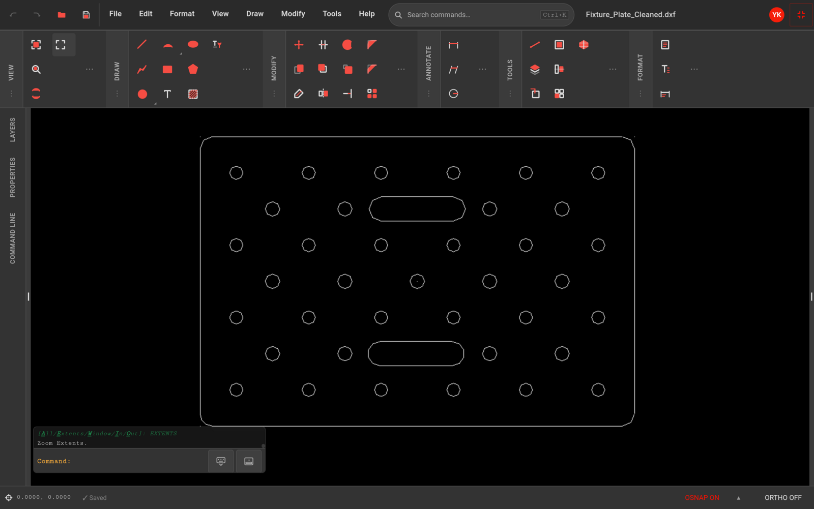
The plate below is drafted in SnapCAD like any other CAD drawing: a fixture plate for an optical bench, with 24 holes at 5.5 mm and 13 at 6 mm.
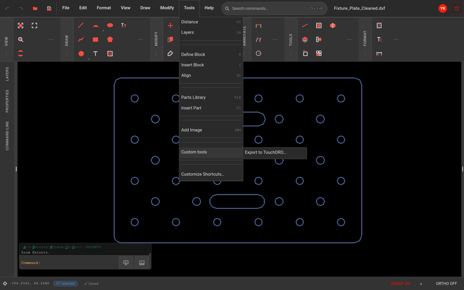
To export it for TouchDRO, open the "Tools" menu, then "Custom tools", then "Export to TouchDRO…". SnapCAD writes a file in TouchDRO's own drawing format, with the geometry already converted, so TouchDRO doesn't need to interpret a DXF file. You can follow the rest of this guide the same way with a DXF file exported from any other CAD program.
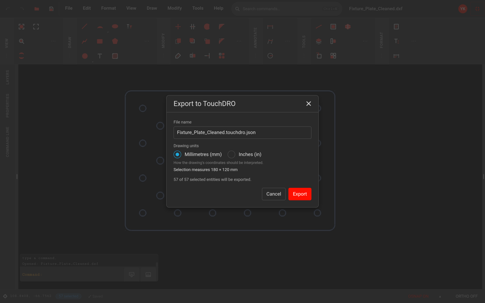
The export dialog asks for one real decision: the drawing units. Pick the units the drawing was drafted in, and check the "Selection measures" line against a dimension you know; this plate should measure 180 by 120 mm, and it does. TouchDRO will trust the units recorded in the exported file, so a wrong choice here imports the plate 25.4 times too large or too small.
Importing the Drawing
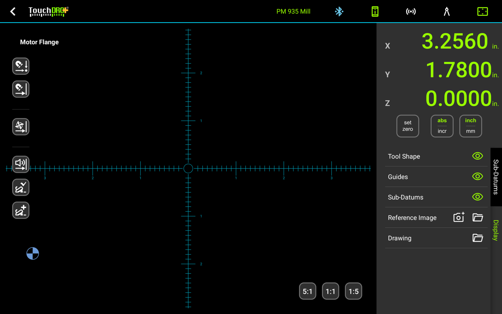
SnapCAD runs in the browser, so you can export right on the tablet: save the file to the internal storage, then open the "Display" panel in TouchDRO's graphical view and tap the folder button on the "Drawing" row. Pick the saved file in the system file picker.
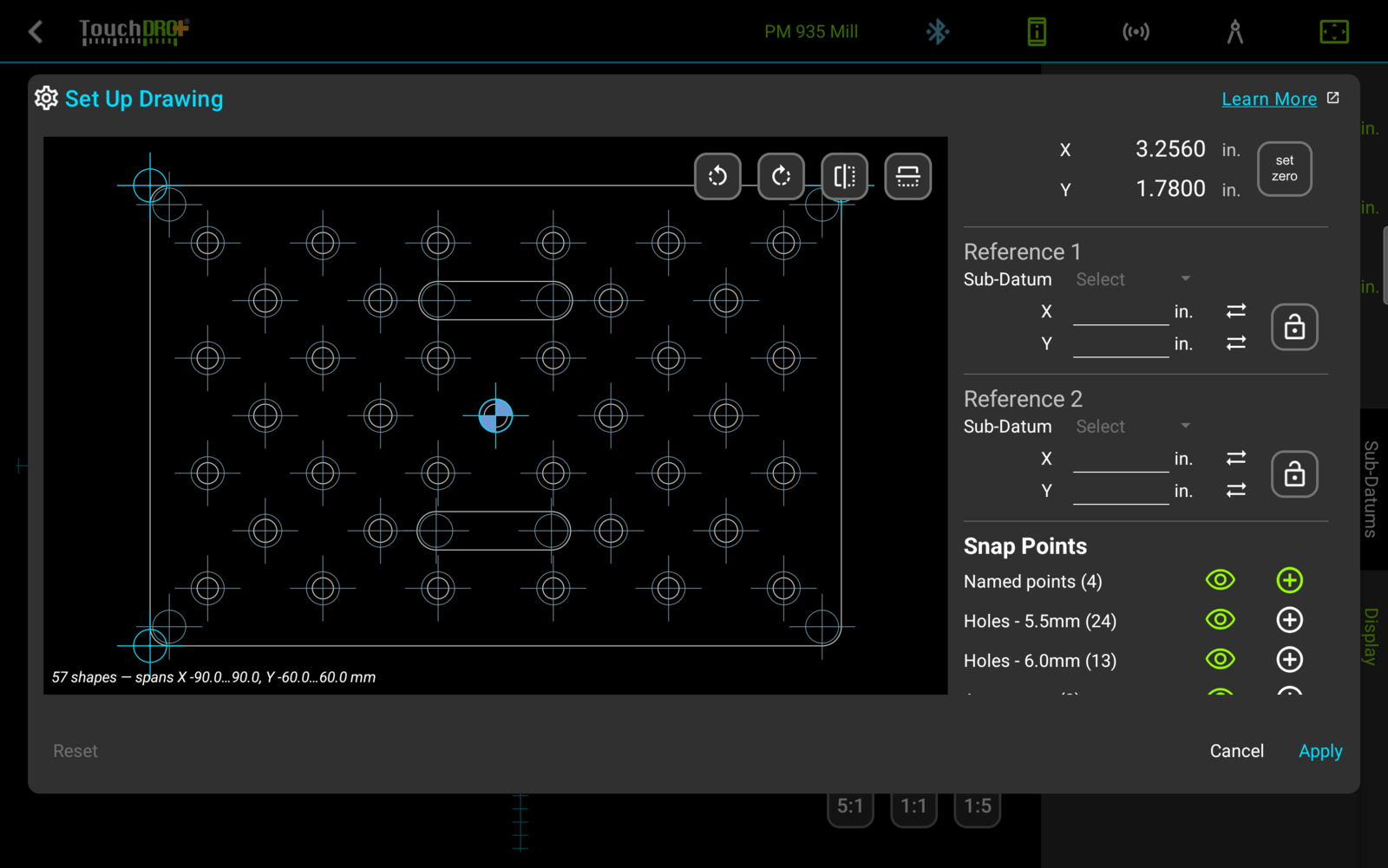
Picking the file opens the "Set Up Drawing" dialog with the plate already fitted into the preview. The fields and buttons in this dialog are covered in full in the "CAD Drawing Import" guide; this walkthrough only touches the ones this plate needs.
If you import a DXF file instead, TouchDRO will convert it before the dialog opens, as described under "Converting a DXF Drawing" in the manual.
Placing the Drawing
This plate was drafted around its center, so the drawing opens with its datum in the middle: the status line reports the spans running from -90 to 90 mm in X and -60 to 60 mm in Y. At the machine, the lower-left corner of the plate is the more convenient origin, and moving it there takes one reference point. Tap the corner's snap point in the preview; the tap is echoed by a marker and by the picked position on the status line.
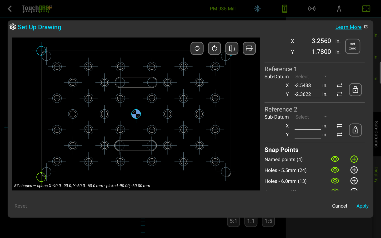
Type 0 and 0 into the "Reference 1" X and Y fields, then press the lock button. The whole drawing shifts so the corner becomes the origin, and the status line now reports the spans from 0 to 180 mm and 0 to 120 mm.
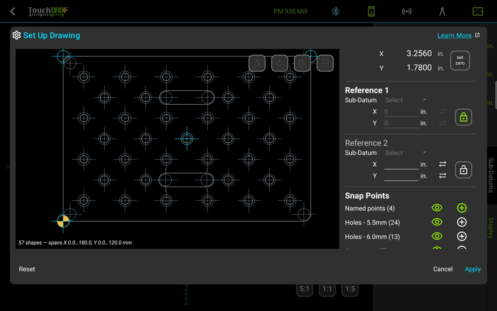
This one step is what ties the drawing to the physical part. Set the machine's absolute origin at the matching corner of the stock, with an edge finder or the "Edge Finder (Indicate Workpiece)" function, and the drawing lines up with the plate on the table: every hole in the drawing sits over the hole's place in the metal.
A second reference point is needed only when the part can't be mounted square and the drawing has to be rotated to match it. It plays no part in scale, since TouchDRO trusts the units recorded in the file at export; that is why the units choice in SnapCAD's export dialog matters. "Apply" is already available, but there is one more thing to set up first.
Extracting Sub-Datums by Hole Size
A complex part often carries several different hole sizes, and the import sorts them out on its own. Each diameter gets its own row in the "Snap Points" panel, and its sub-datums are tagged with the size, such as "Hole_5.5mm". During machining, a whole size can be hidden while another is being drilled, so the wrong-size holes are simply not there to hit. How tags work in general is covered in the "Sub-Datum Tags and Filtering" guide.
Scroll the "Snap Points" panel down to see all four groups. Switch on the "+" button for "Holes - 5.5mm", "Holes - 6.0mm", and "Arc centers", leaving their eyes on so the points stay visible on the preview. This plate has no named points worth keeping, so leave the "Named points" row switched off, then tap "Apply".
The eye toggles are worth a look even when nothing is being created. The drawing itself shows each hole as a circle; the snap point markers sit on the centers, so with the eyes on, the preview shows exactly where every drill will land.
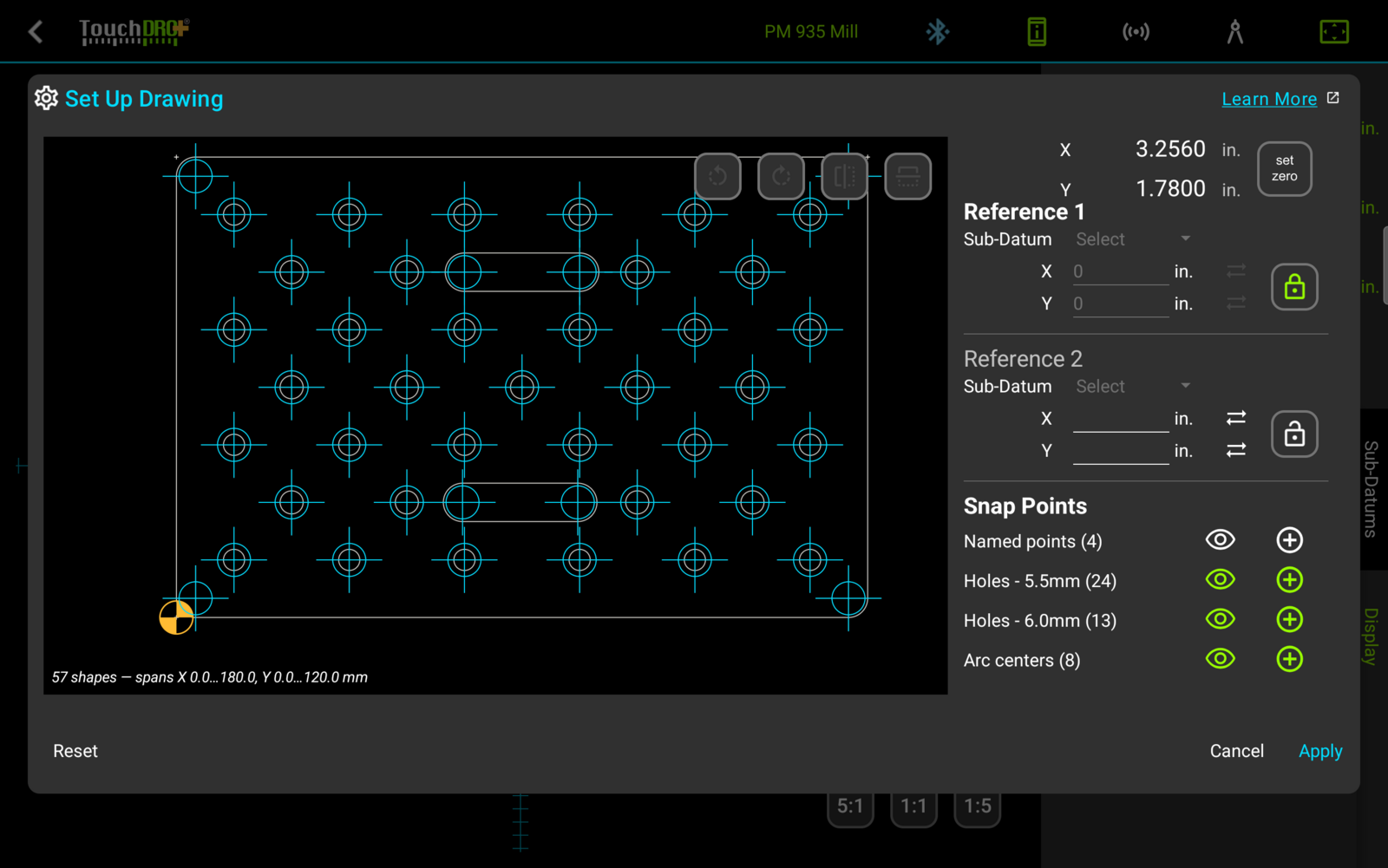
TouchDRO creates 24 sub-datums tagged "Hole_5.5mm", 13 tagged "Hole_6mm", and 8 tagged "Arc_Center" for the rounded corners and the two slot ends, one tag per group. The plate itself drops into the workspace as a drawing layer. Grouping the holes by diameter here is what makes the next section possible: the two hole sizes stay separately filterable, instead of landing in one undifferentiated pile of imported points.
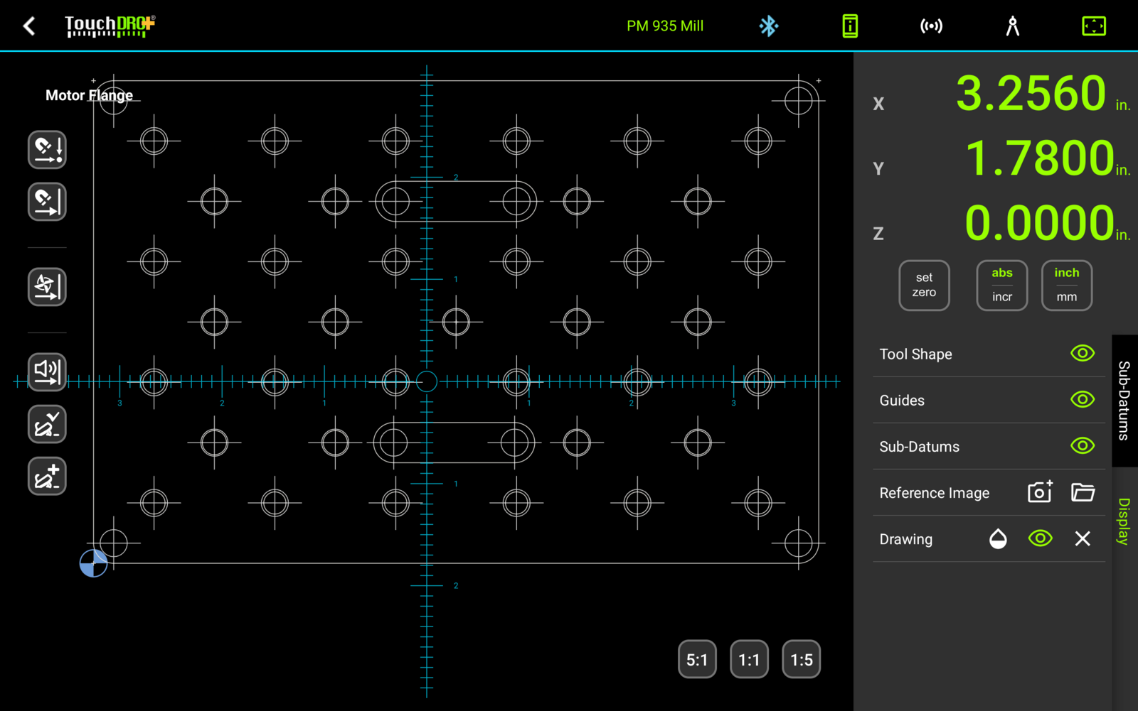
Working the Layout with the Display Panel
The 5.5 mm holes on this plate are meant to be tapped, and the 6 mm holes are meant to be reamed for dowel pins. Drilling a single 6 mm bit through a hole meant for a 5.5 mm tap drill ruins the thread before it is cut. Running down every hole with both bits, in whatever order they are encountered, is exactly how that mistake happens. Tagging the two sizes separately at import turns that risk into a simple sequence:
- Spot-drill every hole first, with both the "Hole_5.5mm" and "Hole_6mm" tags shown. A center drill doesn't care about the final size, so nothing is gained by separating them yet.
- Open the Display panel and hide the "Hole_6mm" tag, leaving only the "Hole_5.5mm" points visible and selectable. Drill and tap those 24 holes; the 6 mm holes aren't on screen to be picked by mistake.
- Swap the two eyes: show "Hole_6mm" and hide "Hole_5.5mm". Drill and ream the 13 remaining holes.

The screenshot above isolates a single tag this way. The same two eyes are what you'd switch back and forth on to swap between "Hole_5.5mm" and "Hole_6mm" in the sequence above. It also shows the plate itself dimmed to half opacity, which is the drawing's default appearance once a Display panel row is expanded like this: the drawing stays visible as a reference for the outline and the slots, but at half brightness it doesn't compete with the sub-datum tags for attention.
A drawing with more than one layer expands the same way under its own "Drawing" row, one eye per layer. That is a separate control from the tag rows above it: layers come from the CAD file itself, such as construction geometry or a points layer meant only for reference, while tags come from how the points were extracted or labeled afterward. Both are covered together in the "Graphical View Display" guide, and tagging in general is covered in the "Sub-Datum Tags and Filtering" guide.
This guide only used the controls the plate needed. The full reference for the import is the "CAD Drawing Import" manual page. And when the part you need to match exists only as a physical object, with no drawing at all, the "Machining a Part from a Photo" guide covers the same kind of job working from the tablet's camera instead of a CAD file.