
Edge Finder (Indicate Workpiece) Function
The "Indicate Workpiece" function (AKA the "Edge Finder") offers a convenient way to locate the edges or the center of a workpiece with the digital readout. The function can be used with an electronic edge finder connected to the TouchDRO adapter, or with a manual edge finding device.
In day-to-day use, this is how you set zero on the edge, centerline, or bore center of a part. The tip diameter math is handled for you, so the origin lands on the feature rather than half a tip away from it.
The function can be activated by the "Edge Finder" button from the function strip at the bottom of the main DRO display. When pressed, it brings up the "Indicate Workpiece" dialog, as shown below.
User Interface Overview
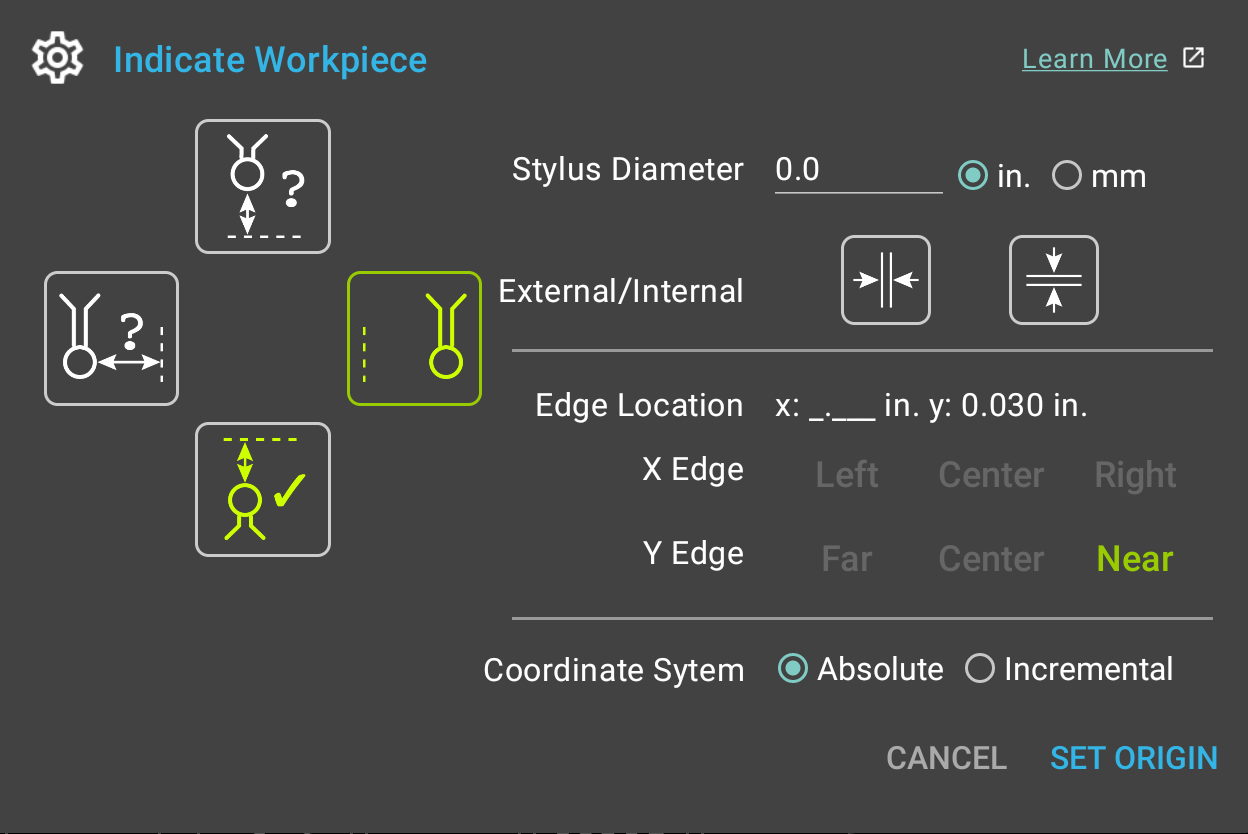
The dialog follows the instrument you select. A probe or an edge finder measures by touching, so it gets buttons for the four edges and a control for which side of the tip met the wall. A camera measures by being aimed, so those controls give way to a set of crosshairs. Everything else is common to both.
Every position the dialog captures comes from the scales, so it needs the adapter connected. The dialog can still be opened without a connection, but a banner across the top says positions can't be captured, and the capture controls stay disabled until the connection returns.
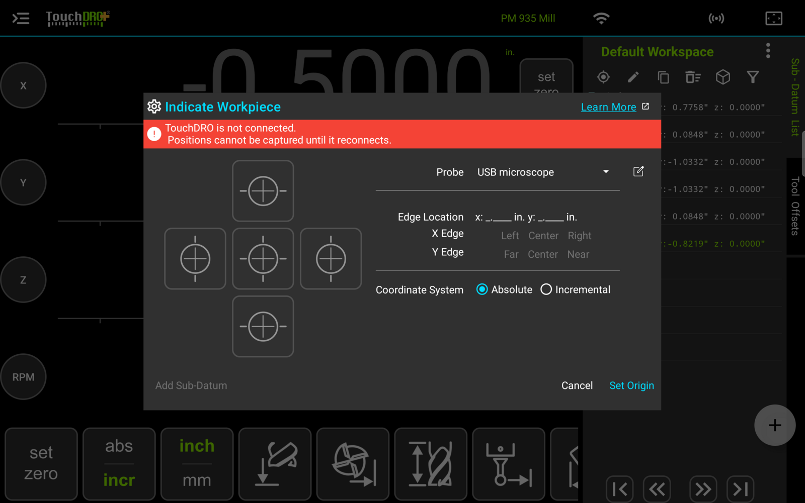
Probe Selector
The "Probe" list selects the instrument being used to find the edge. TouchDRO compensates with the tip diameter stored in the selected profile, so the dialog needs no dimensions typed in at the machine. The list holds every probe in the probe library, and the line under each name states the instrument type and its tip diameter.
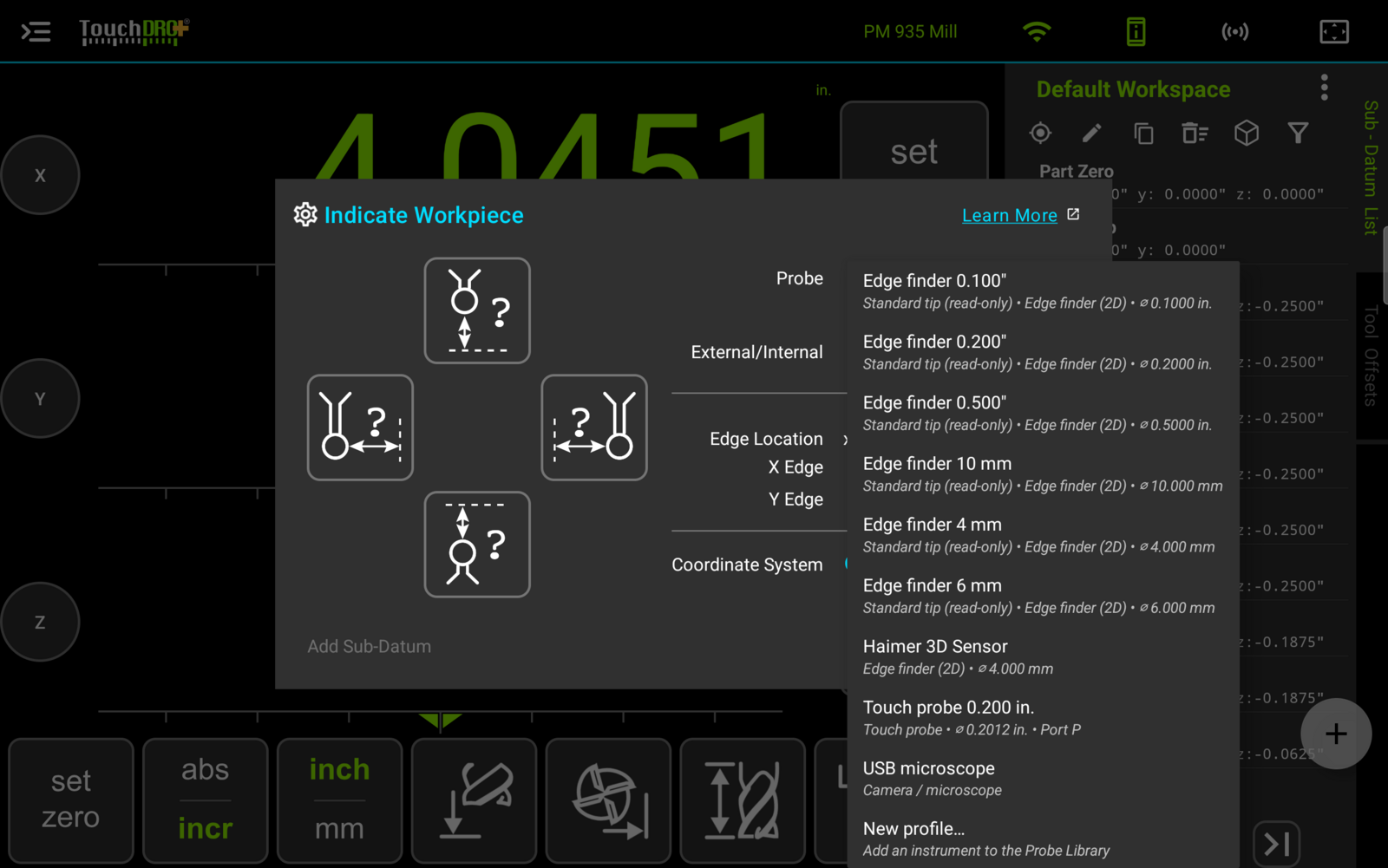
To set up an instrument that isn't on the list yet, tap "New profile" at the bottom of it. Both that and the edit button beside the list open the profile editor, which the probe profiles page covers in full.
Stylus Diameter
This is a required field that is used to tell TouchDRO the diameter of the edge finder stylus. The value is then used to automatically compensate for the radius offset when an edge is indicated.
This value is stored in the persistent state and will be pre-filled next time the dialog is opened to avoid unnecessary data entry.
Stylus Diameter Units Selectors
Stylus diameter units can be selected independent of the default units set in the application preferences.
Toggling between inches and millimeters will convert the value of the stylus diameter field to the selected units. The selection is not persisted and will default to the units selected in the application settings.
Edge Selector Buttons
The left side of the dialog contains the four edge selection buttons for the Left, Right, Near and Far edges that are used to tell the application which edge is being indicated.
Whether an edge can be armed and waited on follows the selected profile. A profile wired to a trigger port gets the full three-state button; a profile with its trigger source set to "None" has nothing to wait for, so the middle state is skipped.
With a trigger port, each button has three states:
- Idle - the button is inactive and the edge has not been indicated
- Pressing the button will activate the scanning mode for the relevant edge. If any other edge was in the scanning mode, it will return back to the idle state
- Long-pressing the button will skip the scanning process and will use current spindle position to indicate the edge.
- Scanning - TouchDRO is waiting for electronic edge finder trigger to indicate the edge
- Pressing the button will deactivate the scanning mode and will return it to the Idle state.
- When the edge finder input is triggered, TouchDRO will record the position and switch to "Indicated" state. The edge can then be used to set the origin
- Indicated - the edge has been indicated and can be used to set the origin
- Long-pressing the button will clear the indicated position and return the button to Idle state
Without a trigger port, the Scanning state is omitted. Pressing a button in the Idle state records the current position, the way a long-press does above, and pressing an indicated button clears it again.
External/Internal Buttons
The two "External/Internal" buttons determine whether an internal or external feature is being indicated. Their state sets the direction of tip diameter compensation.
Z Position
The "Z Position" row brings the Z axis into the same operation, so a face can be picked up along with the edges rather than in a second pass. The row appears for an instrument that can measure Z, which means a touch probe. To include it, turn on the switch at the end of the row. A Z-only touch-off, with no edges involved, is the job of the separate Set Z Reference function.
The value can be filled in three ways. Type it, tap the sync button to take the current Z reading, or tap the arm button to arm the probe so the next touch captures it. Whichever route it arrives by, the setter height or probe offset from the selected profile is applied, and pressing "Set Origin" then sets Z along with the axes that have edges indicated.
Edge Location
The read-only Edge Location text box displays the location of the selected edge/center point in relation to the current absolute origin. The position is displayed for information purposes only and can not be edited directly.
X and Y Origin Selector Buttons
Below the "Edge Location" text box are two rows of three toggle buttons, one row per axis, that provide a way to select the relative location of the origin:
- When one of the edges is indicated, the corresponding button will be activated
- When both edges are indicated, all three buttons will be enabled and the "Center" button will be activated automatically
- Pressing any of the enabled buttons toggles it on and off
Coordinate System Selector
When the "Indicate Workpiece" function is activated, it will default to the Absolute coordinate system. Coordinate system selector radio buttons provide a way to toggle between the Incremental and Absolute coordinate system as needed.
TouchDRO Plus Features
Auto Button
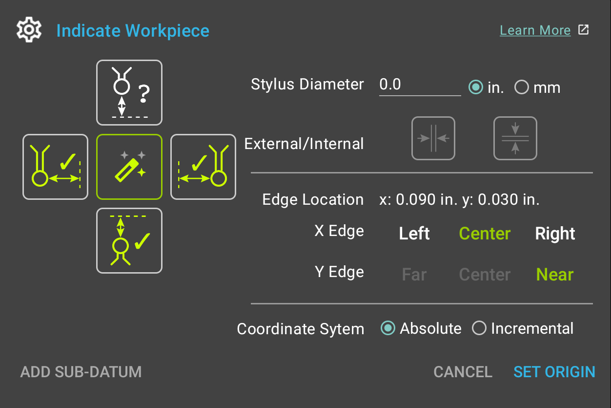
The "Auto" button (also called "Magic Wand" button) in the center of the Edge Selection buttons is available in TouchDRO Plus, and is used to automatically select the edge based on the direction of axis travel when the probe is triggered.
Note, that when the auto mode is enabled, External/Internal buttons are disabled.
Add Sub-Datum Button
The "Add Sub-Datum" button is available in TouchDRO Plus. It can be used to add the indicated edge as a sub-datum coordinate. This button has two modes:
- Short press - adds current point to the sub-datum list, and clears the located edges.
- Long press - adds current point to the sub-datum list, but does not clear the located edges.
Because the button saves a located edge or center rather than the spindle position, the point that lands in the list is the compensated one, measured where the instrument actually touched.
Camera Controls
Camera and microscope profiles are a TouchDRO Plus feature, and selecting one swaps the touching controls out. The four edge buttons take crosshair artwork, since there is no tip approaching a wall to draw. A center button appears between them in place of the wand. The "External/Internal" row disappears, because inside and outside describe which side of a tip met the wall and a crosshair has no tip. The "Z Position" row disappears as well, since a camera doesn't measure Z.
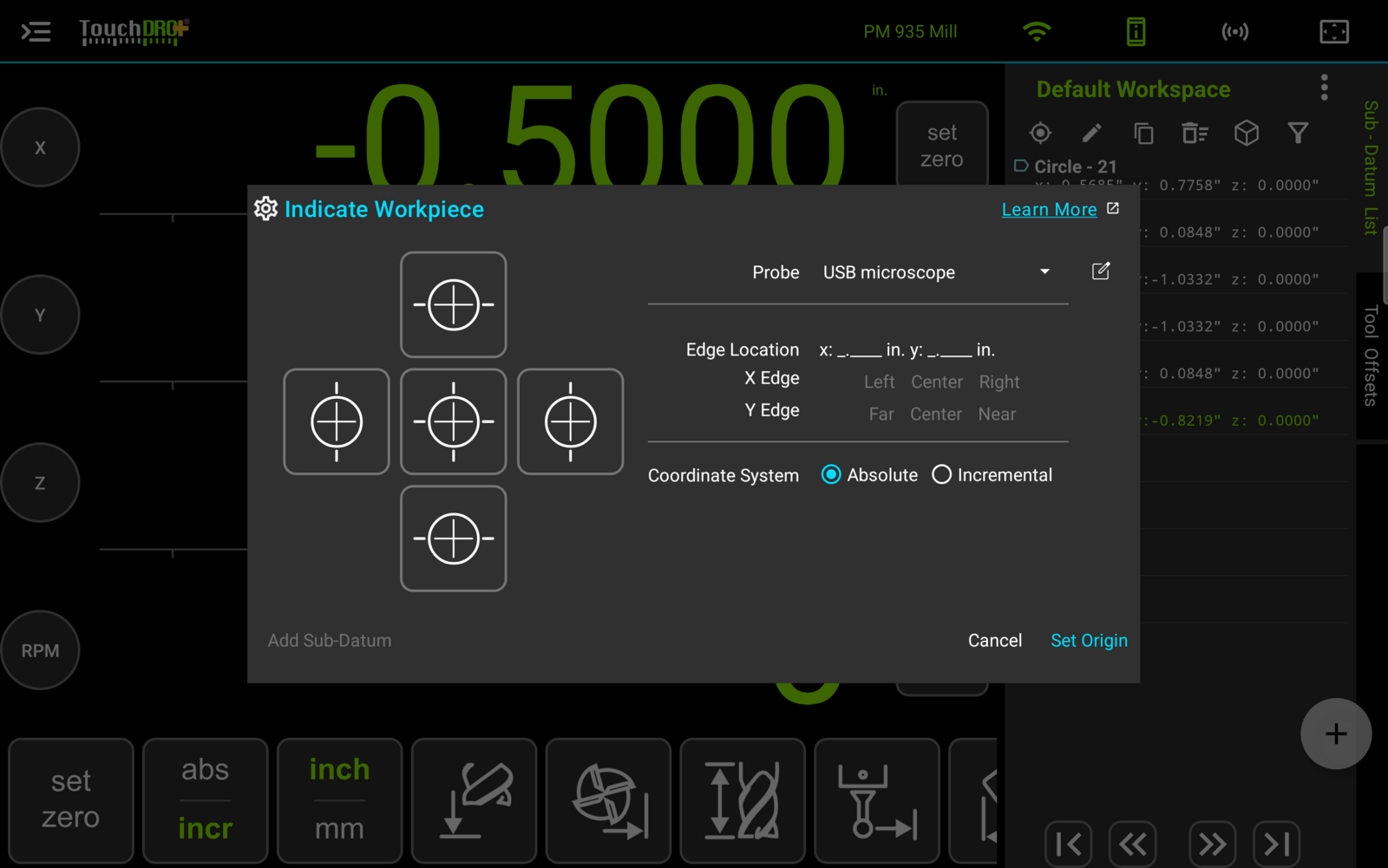
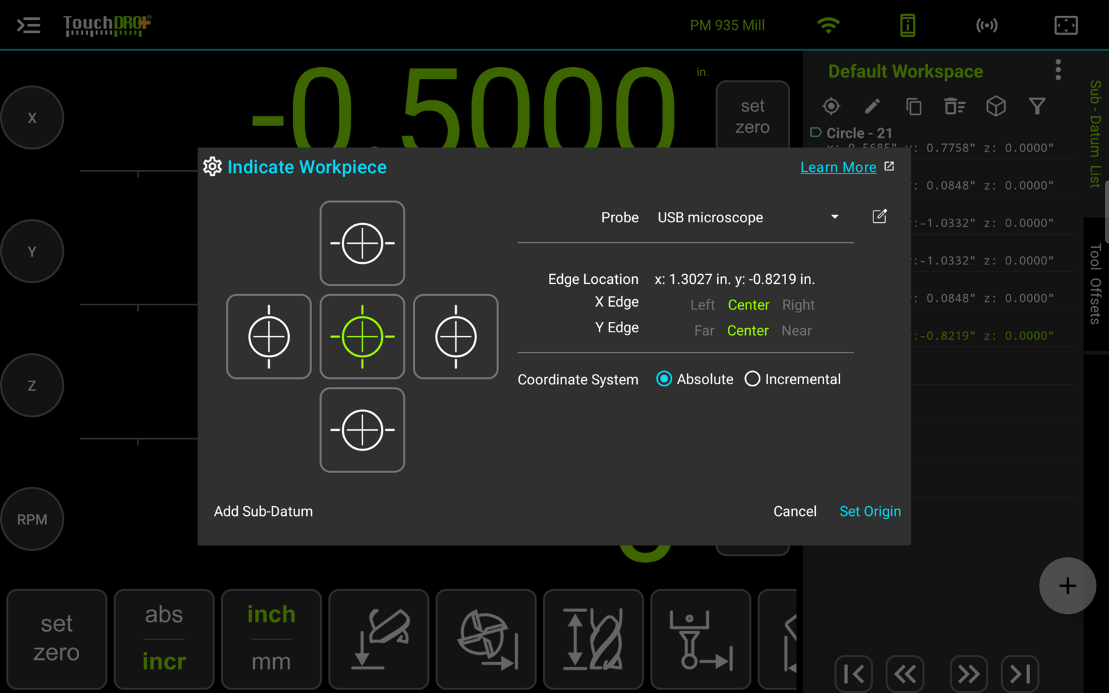
Each edge button carries a crosshair line in the direction it measures, which is also the line to lay on the edge. The left and right buttons show the vertical line, since an X edge is picked up by putting that line on it, and the near and far buttons show the horizontal one. The center button takes the position under the crosshair as the center in both X and Y at once.
Working With the Indicate Workpiece Function
Indicating an Edge With a Manual Edge Finder
Indicating one of the four edges of a workpiece consists of the following steps (using left edge as an example):
- Bring up the "Indicate Workpiece" function dialog
- Check that the tip diameter matches the instrument you are using; it is usually already set from previous use
- Move the spindle to the left of the workpiece and lower it as needed
- Move the spindle towards the left edge of the workpiece until the edge finder is triggered
- Long-press the left edge selector button; once TouchDRO emits a "long" beep, the button will switch to the "indicated" state
- TouchDRO will automatically activate the "Left" button for the X Axis Origin
- If desired, tap the "Incremental" radio button to set the incremental origin
- Press the "Set Origin" button
If desired, the origin for the second axis can be set at the same time by repeating steps 3-5 for the desired edge.
Indicating an Edge With a Touch Probe
The process of indicating the workpiece edge with an electronic touch probe is similar to the process described above and consists of the following steps:
- Bring up the "Indicate Workpiece" function dialog
- Check that the tip diameter matches the instrument you are using; it is usually already set from previous use
- Move the spindle to the left side of the workpiece
- Press the left edge selector button; the button will display "scanning" animation
- Slowly move the axis until the probe touches the left edge and is activated; the edge selector button will change to the "Indicated" state
- TouchDRO will automatically activate the "Left" button for the X Axis Origin
- If desired, tap the "Incremental" radio button to set the incremental origin
- Press the "Set Origin" button
Analogous process can be used to find any of the other three edges as needed.
Finding the Centerline of a Workpiece
Traditional DRO consoles offer this as the "1/2" function, also called the "half" or "centerline" function: indicate one edge, indicate the other, and the readout splits the distance. TouchDRO folds the same operation into this dialog, and activates the "Center" button for you once both edges are in.
- Bring up the "Indicate Workpiece" function dialog
- The tip diameter is irrelevant for a centerline, because the compensation cancels between the two edges; any instrument selection will do
- Move the spindle to the left side of the workpiece
- Indicate the left edge:
- If using an electronic edge finder:
- Press the left edge selector button; the button will display "scanning" animation
- Slowly move the axis until the probe touches the left edge and is activated; the edge selector button will change to the "Indicated" state
-
If using a manual edge finder:
- Move the edge finder towards the left edge of the part until the edge finder is triggered
- Long-press the left edge selector button
- If using an electronic edge finder:
- Repeat steps 3 and 4 for the right edge of the workpiece
- TouchDRO will automatically activate the "Center" button for the X Axis Origin
- If desired, tap the "Incremental" radio button to set the incremental origin
- Press the "Set Origin" button
Finding the Center of a Hole
Hole centering is the same half-the-distance operation applied on both axes, and it works on a bore, a boss, or any feature you can touch from opposed sides.
- Bring up the "Indicate Workpiece" function dialog
- The tip diameter is irrelevant for a hole center, because the compensation cancels between the two edges; any instrument selection will do
- Move the spindle to the approximate center of the hole
- Indicate the left edge:
-
If using an electronic edge finder:
- Press the left edge selector button; the button will display "scanning" animation
- Slowly move the axis until the probe touches the left edge and is activated; the edge selector button will change to the "Indicated" state
- If using a manual edge finder:
- Move the edge finder towards the left edge of the part until the edge finder is triggered
- Long-press the left edge selector button
-
If using an electronic edge finder:
- Repeat steps 3 and 4 for the right edge of the workpiece
- TouchDRO will automatically activate the "Center" button for the X Axis Origin
- Repeat steps 3 through 5 for the Y axis
- TouchDRO will automatically activate the "Center" button for the Y Axis Origin
- If desired, tap the "Incremental" radio button to set the incremental origin
- Press the "Set Origin" button
Working With a Camera or a Microscope
A camera, a USB microscope, or a dedicated centering microscope measures by being aimed rather than by touching, and on a manual mill that turns out to be the quickest way a digital readout can pick up a feature. There's nothing to arm, no approach to creep in on, and no touch to make. You bring the crosshair onto the feature and tap a button.
It's also the instrument that resolves what a stylus can't. A scribed line, a center punch, a cast or flame-cut edge, the corner of a thin part, a chipped tooth: none of these give a probe a clean wall to trigger against, and all of them are plainly visible under magnification. Where a stylus has to infer the feature from where it stopped, the crosshair puts you on the feature itself.
The third advantage is the mounting. A camera on its own bracket beside the spindle stays there through the whole job, so picking up a position costs no tool change: nothing comes out of the collet and nothing goes back in, and the tool you were cutting with keeps its setting. The X and Y offsets in the probe profile are what make this work, since they put the reading back on the spindle axis. The accuracy you get is the accuracy of those two numbers, so they are worth measuring carefully once.
For anything you can see the whole of and judge the middle of by eye, such as a hole, a boss, a punch mark, or the intersection of two scribed lines, use the center button. Line the crosshair up on the feature, tap the button, and both axes take that position as the center. To set the origin there, press "Set Origin"; to record it as a point instead, press "Add Sub-Datum". Tapping the center button a second time releases the capture.
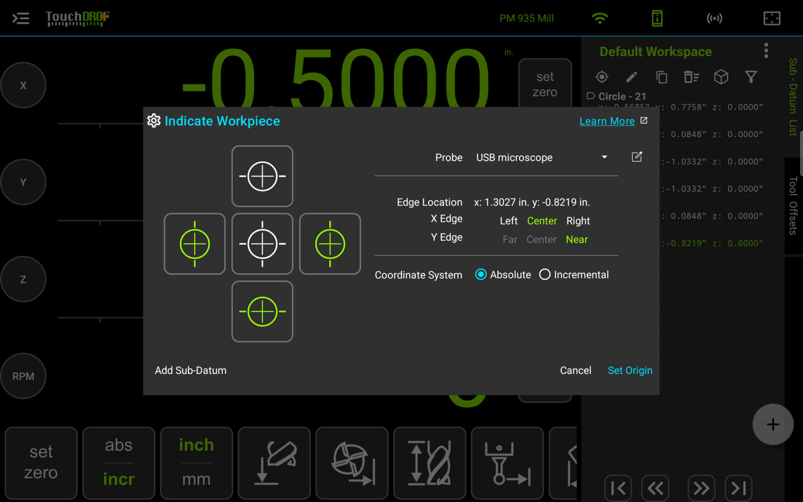
To pick up an edge, aim the crosshair line at it and tap the button for that edge, the way an instrument with no trigger port works. Tapping an indicated button again clears it. From there the origin selector rows behave as they do with any other instrument: two opposed edges enable Left, Center and Right for that axis, with Center chosen automatically.
Measuring a Part That Has No Drawing
Copying a worn part, reverse engineering a mating component, or fitting a repair all start the same way: the dimensions have to come off the part itself. Writing them on a notepad is where they get transposed, and a part measured over several sittings tends to end up with several slightly different reference points.
The "Add Sub-Datum" button, available in TouchDRO Plus, turns this function into a way to record the whole part in one coordinate system. Set the absolute origin once, against a corner or a face you can find again, then work through the features:
- Indicate the feature as described above, using one edge for a face, two for a center, or the camera's center button for anything you can aim at
- Long-press "Add Sub-Datum" to save the point and keep the located edges, or short-press it to save the point and clear them for the next feature
- Rename the point in the sub-datum list while you still remember which feature it was
Features you can simply jog to don't need the function at all. Position the spindle and tap the add button at the bottom of the sub-datum panel, and the current position is saved as a point.
A camera is worth reaching for on this kind of work in particular. A part that has no drawing usually has no clean machined edges either, and the features that matter are as likely to be scribed, punched, or cast as milled.
Once the part is covered, the workspace holds every hole center, edge, and boss center that was measured. Exporting it writes that set out as a DXF drawing to take into CAD, where the points become anchors to draw against instead of a column of numbers to retype.
Recording where the features are is not the same as measuring them. To get the distance between two of them, the center and diameter of a bore from three points on its wall, or the angle an edge runs off square, switch the app into measurement mode and use the measuring functions. Those keep an inspection log of what you measured as well, which the sub-datum list does not.
Notes
Edge finder diameter field can't be left blank; TouchDRO will display an error and origin location selection buttons will not be activated. If the diameter is not needed (for example when locating a centerline of a part), simply enter "0" into the field. The value will be stored in the persistent application state and will be prefilled next time the dialog is opened.
Origin location selection buttons can be toggled on and off when they are enabled, so it's possible to turn all three buttons off. In such a case TouchDRO will not change the origin for that axis.
This dialog can be used to verify touch probe alignment. This can be done as follows:
- Set the dialog up for a reliable manual edge finder, with its tip diameter
- Indicate the left edge (for example) using that edge finder as described in the "Indicating an Edge With a Manual Edge Finder" section above
- Write down the value shown in the "Edge Location" text box
- Long-press the Left Edge selector button to clear the indicated position
- Orient the touch probe so the cable is facing away from you (at 12 o'clock position)
- Set the dialog up for the touch probe, with its tip diameter
- Indicate the same edge using the electronic touch probe as described in the "Indicating an Edge With A Touch Probe"
- Note the new Edge Location value
- Rotate the probe 90 degrees
- Repeat steps 7 and 8, rotate the probe by 90 degrees
- Repeat steps 7 and 8 again, rotate the probe by 90 degrees
- Repeat steps 7 and 8
At this point you will have five numbers - the position found by the edge finder and four positions found by rotating the probe. Ideally, all five numbers should be close to identical. If the positions differ by more than an acceptable tolerance, you will need to adjust and calibrate the probe to achieve better accuracy.