
Mill Tool Library and Tool Offsets
The tool library is one of the underutilized features in TouchDRO. Many machinists skip it, assuming that it takes an indexable tool holder system to get anything out of it. This is not the case.
An endmill's diameter and flute count stay with the cutter for its whole life. Measure a 1/2" four-flute endmill once and the figure is still good the next time it comes out of the drawer, in any collet, on any machine in the shop. The library stores those measurements so every function that needs the size of the cutter can ask for it by name. If you know tool tables from CNC work, this is the digital readout's version of the same idea.
Z offset is the one entry that depends on the holder, which is why the editor treats it as optional. Switch it off and the tool still carries its diameter into cutter radius compensation and its flute count into the chip load calculation.
Opening the Tool Library
To open the tool library, select "Tool Library" from the application menu drawer. This will bring up the "Saved Tools" dialog.
The Tool List
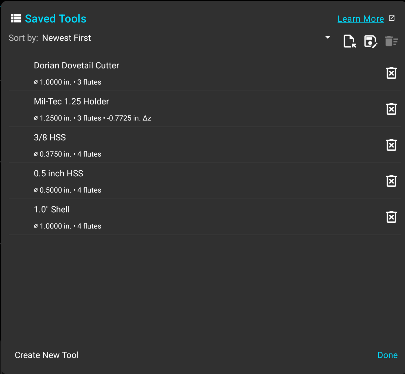
Each row carries the tool's name and, under it, the figures stored against it: the flute diameter, the flute count, and the Z offset where the tool has one. A tool with no height offset ends after the flute count, so the list never shows a compensation that the DRO won't apply.
The "Sort by" selector at the top orders the list by "Newest First", "Oldest First", "Name A-Z", or "Name Z-A". The order applies to this dialog only.
This dialog is where tools are entered, edited and deleted. Applying one to the readout is done from the "Tool Offsets" panel described below.
The Tool Offsets Panel
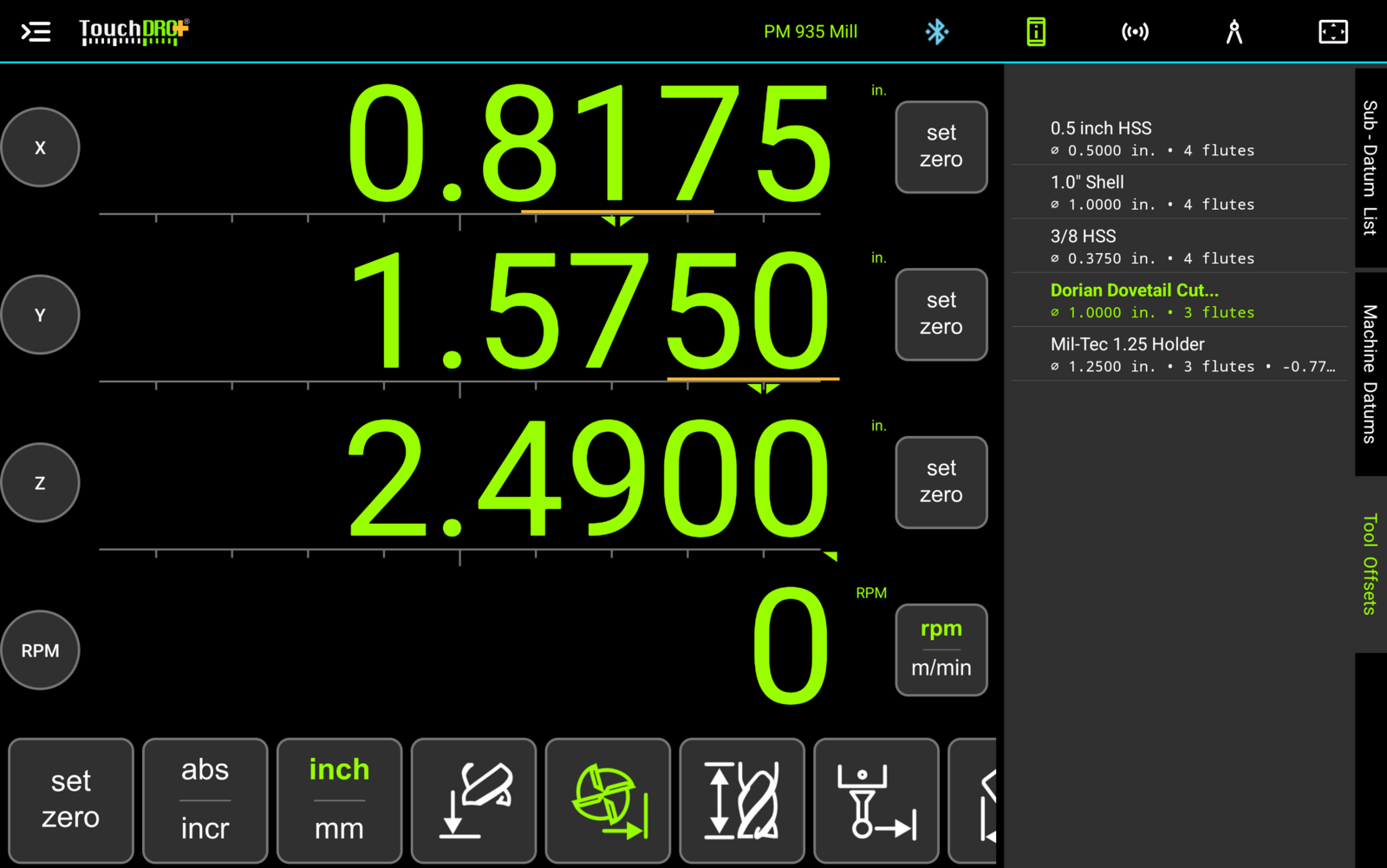
The panel on the right of the main screen has a "Tool Offsets" tab beside "Sub-Datum List" and "Machine Datums", holding the same tools sorted by name. Tools are applied here rather than in the dialog, so a tool change costs one tap on a panel that is already open.
Applying a Tool
To apply a tool, tap its row in the "Tool Offsets" panel. TouchDRO will load the flute diameter and count for cutter radius compensation, apply the stored Z offset, and show the row in green to mark the tool as active. Tapping the row a second time clears both offsets.
TouchDRO applies the radius compensation in the center position, so the X and Y readouts don't shift until you choose a direction. The cutter is drawn in the Graphical View display as soon as the tool is applied, sitting on the spindle position until it has a direction to move to. Directions are covered in "Cutter Radius Compensation".
Adding a Tool
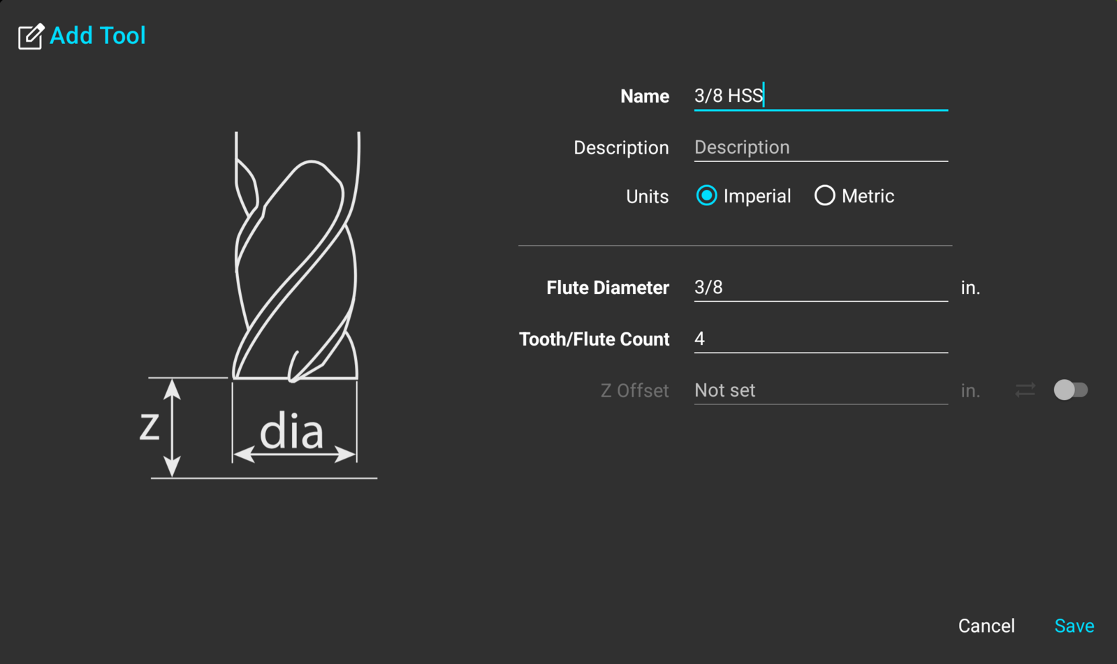
To add a tool, press "Create New Tool" in the lower-left corner of the "Saved Tools" dialog. This will bring up the "Add Tool" dialog, where the drawing on the left shows what each figure describes.
Name and Description
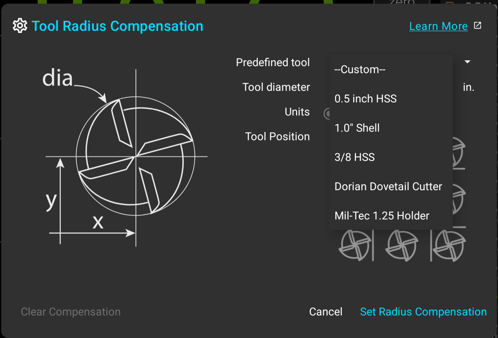
The name is required, and it's what identifies the tool everywhere else in the application: the tool list, the "Tool Offsets" panel, and the "Predefined tool" dropdowns in cutter radius compensation and tool height compensation. Something along the lines of "1/2 4FL Carbide" reads better in those places than a catalog number. The "Tool Offsets" panel is narrow, so a name longer than about 20 characters is shown truncated there.
The description is optional and appears in this dialog and in an exported CSV file. It is a good place for the things that don't fit in a name, such as the holder a tool lives in or the material it is ground for.
Units
Each tool carries its own units, set by the "Imperial" and "Metric" selection. A metric endmill can be entered in millimeters and stored that way on a readout you work in inches, and TouchDRO converts the figures when it applies the tool.
Switching the selection while entering a tool converts whatever is already in the "Flute Diameter" and "Z Offset" fields, so a diameter typed in inches isn't left standing as a millimeter figure.
Flute Diameter
The flute diameter is required and has to be something other than zero. Enter the diameter of the cutter rather than its radius; TouchDRO halves it when it applies radius compensation.
The field accepts arithmetic, so a 3/8" endmill can be entered as "3/8" and a metric cutter measured over two flutes can be entered as the expression that produced it.
Flute Count
The "Tooth/Flute Count" field is required. TouchDRO uses it for the chip load figure in the "Axis Details" dialog, which works out feed per tooth from the feed rate, the spindle speed, and this number.
Z Offset
The Z offset is optional; the switch at the right of the row turns it on and off. Switched off, the field is greyed out and reads "Not set", and the tool is stored with no height offset. Switched on, the field holds the distance between the tip of the cutter and the reference surface it was set from.
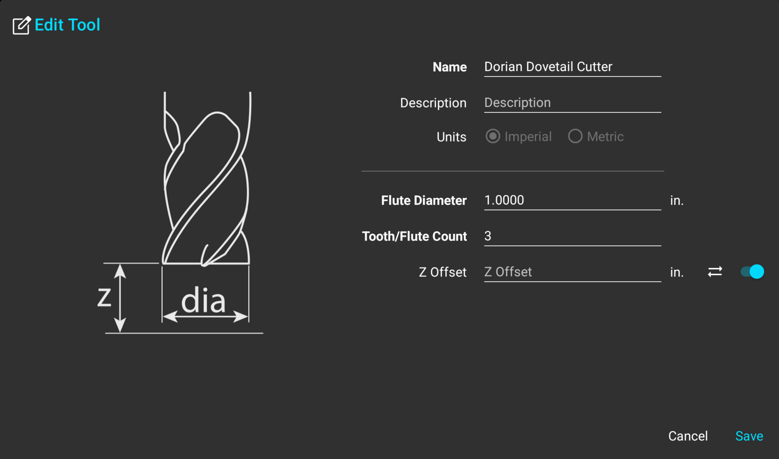
The "Sync" button next to the field fills it in from the current position. Touch the tool off against the surface you are measuring from, then press "Sync"; TouchDRO takes the current Z reading, removes any tool offset that is already applied, and enters the result with the sign flipped, which is the form the stored offset takes.
Measuring offsets for a set of tools is covered in "Using a Tool Height Setter".
Editing and Deleting Tools
To edit a tool, tap its row in the "Saved Tools" dialog. The "Edit Tool" dialog is the same form as "Add Tool" with the stored values filled in and the units selection disabled.
There are two ways to delete tools:
- To delete a single tool, press the delete icon on its row. TouchDRO will ask for confirmation before removing it
- To delete several tools at once, long-press one of the rows. This will switch the list into multi-select mode, where more rows can be checked; the delete button at the top of the dialog removes everything that is checked, after a confirmation that names the count
Importing and Exporting Tools
The Z offset is the only figure in a tool record that has to be measured at the machine. You can read the diameter and flute count off the packet or a pair of calipers, so there is no reason to be standing at the tablet typing them in, and a tablet keyboard is the slowest way to enter a drawer full of endmills.
It is quicker to enter the tools in a spreadsheet, save the sheet as a CSV file, and import the file into TouchDRO in one go, using the "Import" button at the top of the "Saved Tools" dialog. Z offsets can be filled in afterwards from the tool editor, on the tools that need them.
A mill file has one row per tool. The file below is the library shown in Fig. 1, straight out of "Export":
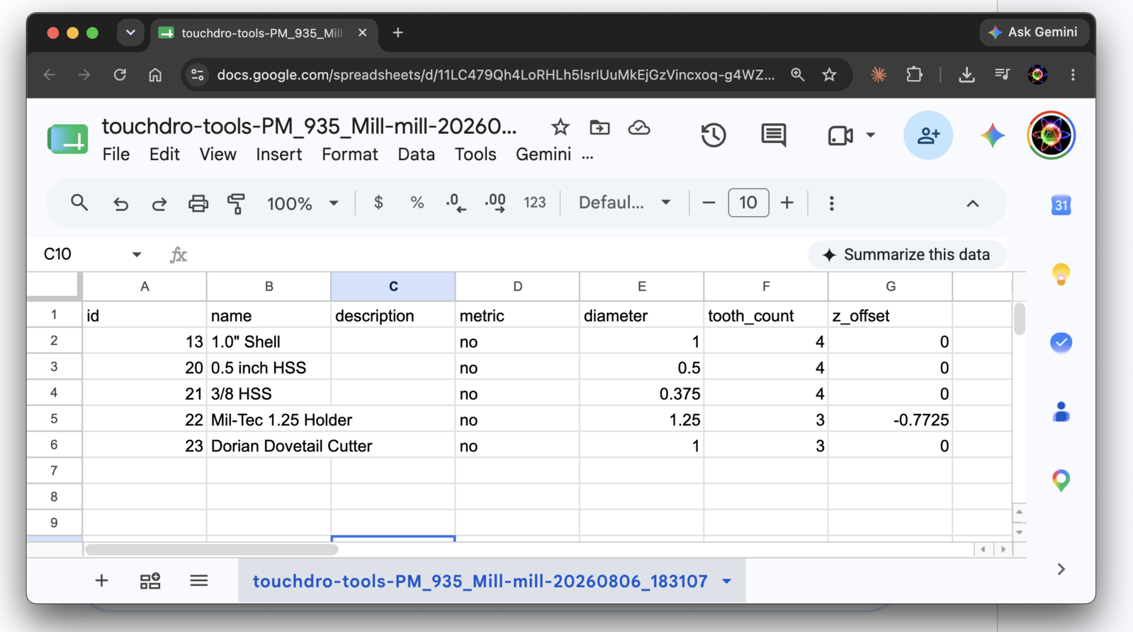
id,  name,                    description,  metric,  diameter,  tooth_count,  z_offset
13,  "1.0"" Shell",           ,             no,      1.0,       4,            0.0
20,  0.5 inch HSS,            ,             no,      0.5,       4,            0.0
21,  3/8 HSS,                 ,             no,      0.375,     4,            0.0
22,  Mil-Tec 1.25 Holder,     ,             no,      1.25,      3,            -0.7725
23,  Dorian Dovetail Cutter,  ,             no,      1.0,       3,            0.0
The metric column records the units each tool was entered in, so a file can hold inch and millimeter tools together. A tool with no height offset writes 0.0 in the z_offset column, and imports back as a tool with the Z offset switched off.
A sheet built from scratch needs four columns: name, metric, diameter, and tooth_count. The id column belongs to records that already exist, so leave it out and TouchDRO will enter every row as a new tool. The description and z_offset columns can be left out as well, and a file with no z_offset column at all is a complete tools file rather than a broken one.
To save the sheet as a CSV file in Google Sheets, use "File", then "Download", then "Comma Separated Values (.csv)". A spreadsheet on the desktop has the same option under "Save As".
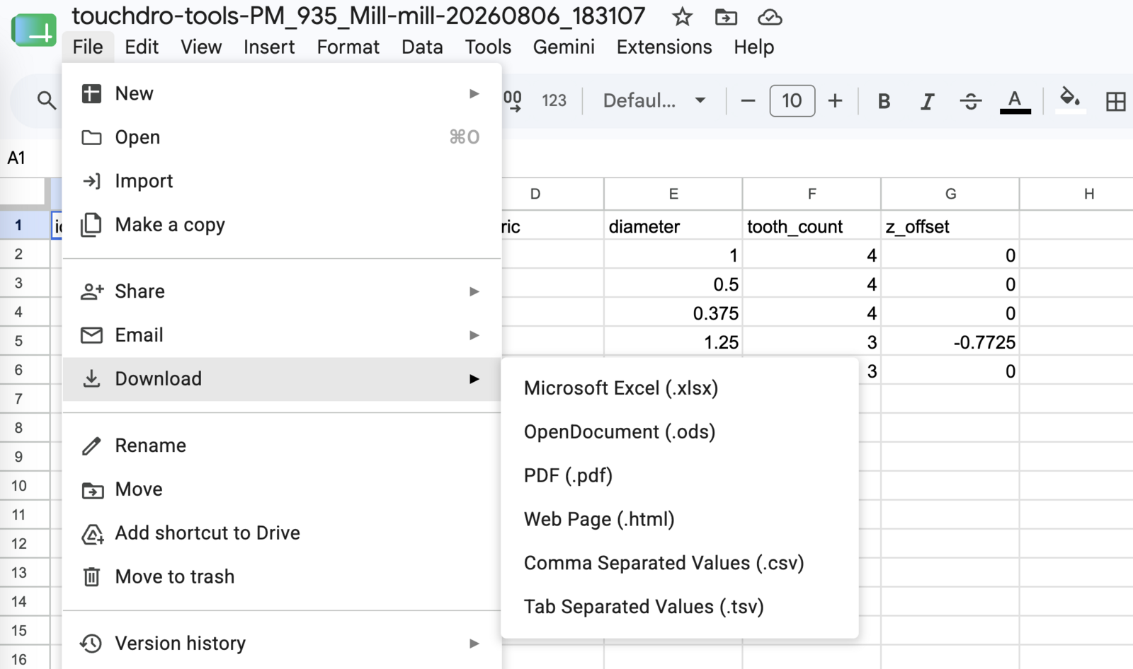
Export writes the whole library, or only the checked rows when the list is in multi-select mode.
The Import Preview
Import shows the file in a preview grid before anything is written, so nothing reaches the library until you press the import button at the bottom of the dialog. The grid scrolls sideways when the columns run wider than the dialog.
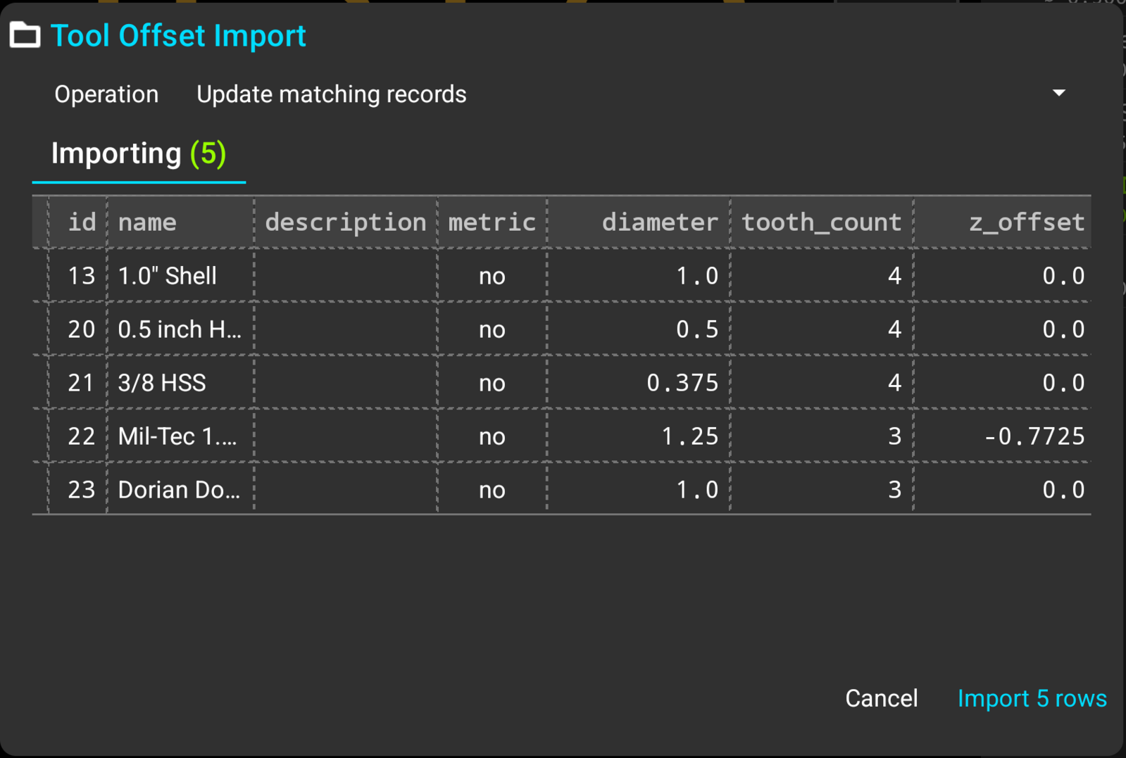
The "Operation" selection at the top decides what the file does to the library. "Add as new records" enters every row as a new tool, and "Replace all existing records" clears the library first. "Update matching records" is offered when the file was exported from this device, and rewrites the tools the ids belong to rather than duplicating them.
The preview, its problem markings, and the rest of the import machinery work the same way as they do for coordinates, covered in "Importing and Exporting Sub-Datum Coordinates".
Where the Library Lives
The tool library belongs to the machine profile, so each profile keeps its own set of tools and a new profile starts empty. Turning on "Use Shared Tool Library" in the application settings keeps one set across every profile instead, which suits a shop where the same endmills go into more than one machine.
Deleting a machine profile deletes the tools stored under it. Profiles are covered in "Machine Profiles".
What the Library Is Used For
Working to the Cutting Edge
The scales on a mill measure the spindle, and the cut is made by the edge of the cutter, half a diameter away from it. Cutter radius compensation shifts the readout by that half diameter in the direction set by the "Tool Position" matrix, and the flute diameter stored here is the figure it shifts by.
TouchDRO also draws the active cutter in the Graphical View display, as a circle at the size of the tool, in position against everything else on the workspace: sub-datums, guide lines, and an imported CAD drawing. The circle is drawn for any active radius compensation, a typed-in diameter included; picking the tool from the library simply means it is the right size every time. A set of coordinates can't show how much material a cutter covers, and a circle drawn to scale can.
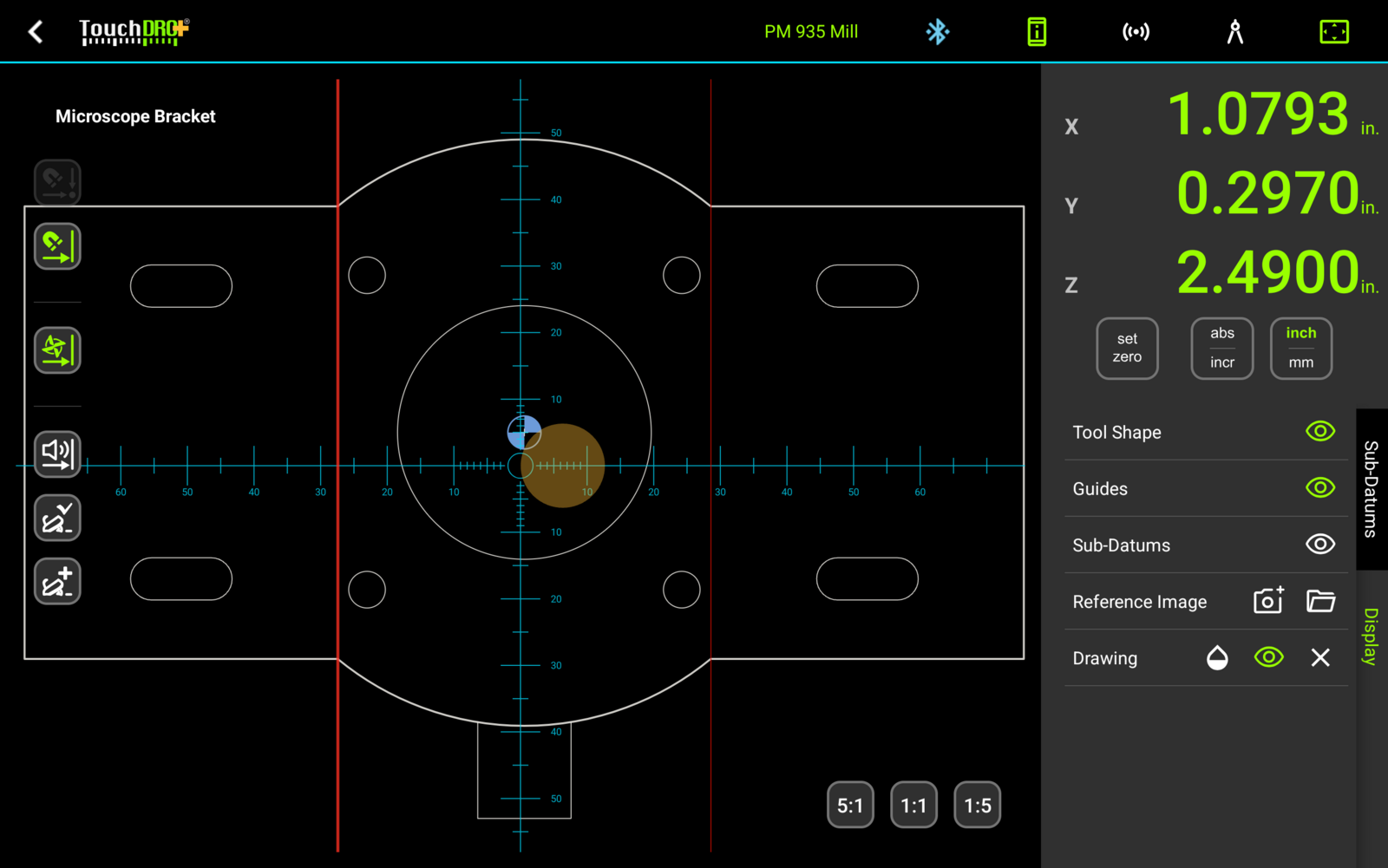
That combination is what makes a complicated profile workable on a manual mill. Draw the part, import the drawing, and the outline sits on the screen at size with the cutter drawn against it. With the "Auto Tool Offset" mode on, activating a guide turns the compensation toward that guide, so the readout shows the cutting edge facing the wall you are cutting and reads zero when the wall is at size. Machining a slot, a rectangular pocket, or a stepped profile is then a matter of working each wall out to its own guide. There are worked examples for a slot and a rectangular pocket, and a drawing taken from CAD to finished part in "Machining to a CAD Drawing".
A large cutter can end up sitting over the guides and sub-datums you are trying to read. The circle can be dimmed to half opacity, or switched off without clearing the compensation, using the "Tool Shape" row of the Display panel, which is covered in "Hiding the Cutter".
Chip Load
Chip load is feed per tooth, and working it out at the machine takes the feed rate, the spindle speed, the flute count, and the diameter. The "Axis Details" dialog shows the figure live, and applying a tool from the library is what supplies the last two numbers.
This works with the tool position left in the center cell, so a tool can be selected for its flute count and diameter alone, with the readout still showing the spindle.
Tool Height Offsets
A stored Z offset is what the tool height compensation dialog applies when a tool is picked from its "Predefined tool" dropdown, and what the tool list applies when a row is tapped. Zero refers to the same surface through a tool change, and the change costs a selection instead of a touch-off.