
Reference Image Overlay
The tablet running TouchDRO has a camera on the back that is usually pretty well corrected for distortion. You can use the camera to take a photo of the part, and use it as a reference layout in the graphical view. TouchDRO will correct the perspective and align the image to the machine coordinates, so the part's features sit in their true positions under the crosshairs.
This works very well for flat parts that don't need to hold tight tolerances: a gasket traced from an old cover, a switch panel with a dozen cutouts, a bracket whose holes need to land just close enough to bolt up, or a decorative piece cut to a printed pattern. For reverse engineering a physical part to real tolerances, a photo is the wrong tool: the probing workflows described in the "Edge Finder (Indicate Workpiece) Function" guide pick up edges and hole centers by touch, and hold the accuracy of the machine rather than of a camera.
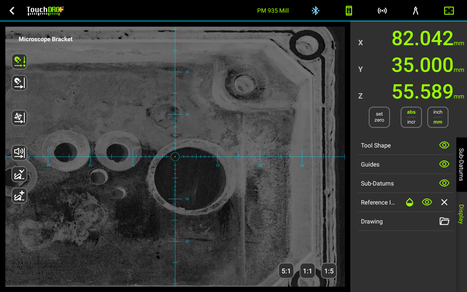
The overlay accepts any JPG or PNG file, including an image exported from CAD. For an actual CAD file, though, the "CAD Drawing Import" function is the better tool: a vector drawing carries its true scale, needs no calibration, and its hole centers and corners can be extracted as sub-datums on the way in. Use the image overlay for what only a camera can capture.
User Interface Overview
The Reference Image Overlay is accessed from the "Reference Image" row of the "Display" panel, described in the "Graphical View Display" guide:
- The camera button opens the default Android camera application, so the photo can be taken without leaving the machine.
- The folder button opens the system file picker for loading an existing JPG or PNG file, such as a photo taken earlier or a scan of a paper drawing.
Once the image is selected, TouchDRO will display the "Align Reference Image" dialog, shown below.
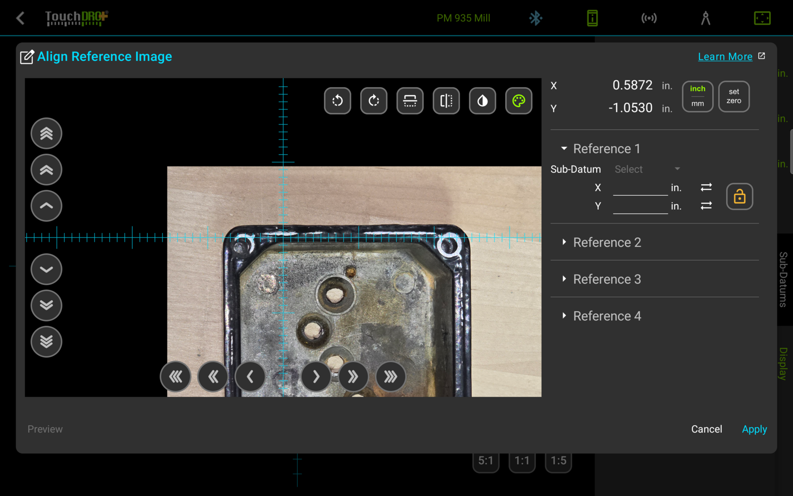
This dialog is used to prepare the image for use as a layout reference. It allows basic manipulations, such as rotation, mirroring, and appearance changes, but its primary function is to calibrate the image to the machine coordinate system.
Image Preview
The majority of the screen is taken up by the Image Preview area, which is used to preview and align the image. Inside the preview area, you can move the image around and zoom in and out using the drag and pinch gestures.
For fine position adjustment, use the chevron buttons along the left and bottom edges of the preview area. The single, double, and triple chevrons move the image by 1, 10, and 100 pixels per tap, so the way to land a feature exactly under the crosshairs is to zoom in and walk the image over with the buttons; there is no need for precise finger gestures to line up pixels.
Image Preparation Buttons
Along the top edge of the preview area there is a row of buttons that manipulate the image. From left to right:
- Rotate left - rotates the image left by 90 degrees
- Rotate right - rotates the image right by 90 degrees
- Flip horizontally - flips the image horizontally (creates a mirror image)
- Flip vertically - flips the image vertically
- Invert colors, marked with a droplet - inverts the image colors (creates a negative image)
- Remove color, marked with a palette - converts the image to grayscale
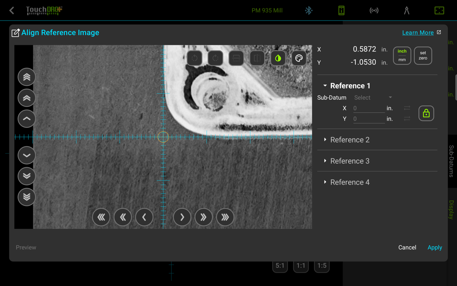
The last two earn their place on a shop screen. A white-background CAD export or paper scan is blinding on a dark display, and a photo often hides its features in color and shadow; with the color removed and the image inverted, either one reads like a blueprint. The screenshots on this page show a photo with both applied.
Position Readout
The Position Readout panel is displayed in the upper-right corner of the window in landscape orientation, or in the lower-left corner in portrait orientation. The panel displays the absolute position readouts for the axes that are appropriate for the current machine type. Additionally, it contains the "Set Zero" button that can be used to set the absolute origin for the two axis readouts.
Reference Points Panel
The Reference Points panel appears either on the right side of the dialog, or underneath the Image Preview area, depending on the screen orientation. It contains four collapsible sections, "Reference 1" through "Reference 4", one per reference point.
Each section holds the same controls: a "Sub-Datum" selector, an X and a Y field, a synchronize button beside each field, and a lock button. The fields take the real-world coordinate of the feature under the crosshairs. The synchronize buttons copy in the current machine position, and the "Sub-Datum" selector fills both fields from a stored coordinate. The lock button locks the reference point in; a locked point can be cleared and redone without disturbing the others.
How to Use
To set a reference background image, follow these steps:
- Tap the camera button to take a photo, or the folder button to select an existing image
- Align the first reference point under the crosshairs; zoom in and use the chevron buttons for the final approach
- Enter the physical position for the selected point, or copy the current machine position into the fields with the synchronize buttons
- Tap the lock button to lock the point
- Repeat steps 2-4 for the other reference points: four for a photo, two for a distortion-free image
- Tap the "Preview" button to check the corrected image; "Return" goes back for further adjustment
- Tap the "Apply" button to set the background
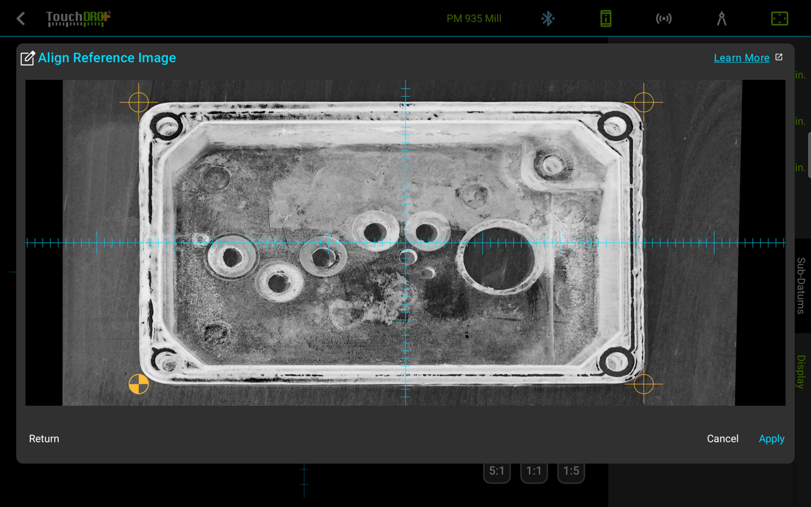
Picking reference features you can locate accurately on the machine is what determines the quality of the result. Two dowel holes, a pair of corners, or any features whose real-world positions are known will work; the further apart they are, the smaller the effect of any measurement error.
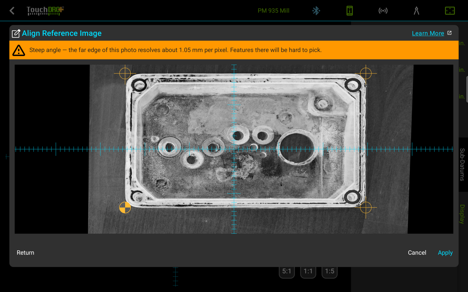
TouchDRO also checks what the reference points imply about how the photo was taken. When the entered coordinates work out to a photo shot at a steep angle, or from very far away, a warning banner names the resolution at the far edge of the photo and says that features there will be hard to pick. In practice, the warning usually points at a typo or a units mistake in one of the reference points: in Fig. 5, one coordinate was entered as 120 inches instead of 120 mm.
When the background is set, the "Reference Image" row of the "Display" panel replaces the camera and folder buttons with three controls: the eye shows or hides the image, the half-opacity button dims it so the sub-datums and cutter stay legible against it, and the clear button removes it from the workspace after a confirmation.