
Lathe Cutter Geometry
A digital readout shows the position of the tool tip, but on a lathe the rest of the tool can cause problems too. For example, the back of a boring bar can rub on the far wall of a small bore, a threading tool can run out of room before it reaches the shoulder, or the heel of an insert holder can touch the face of the part before the tip does.
To help with this, TouchDRO provides a way to attach an outline of the cutter to a tool in the tool library. When the tool is applied, TouchDRO will draw the outline to scale in the graphical view, positioned on the tool tip. This is useful when you need to check the clearance before the tool gets there, since you can see the cutter next to your guides, sub-datums, a thread profile, or an imported drawing of the part.
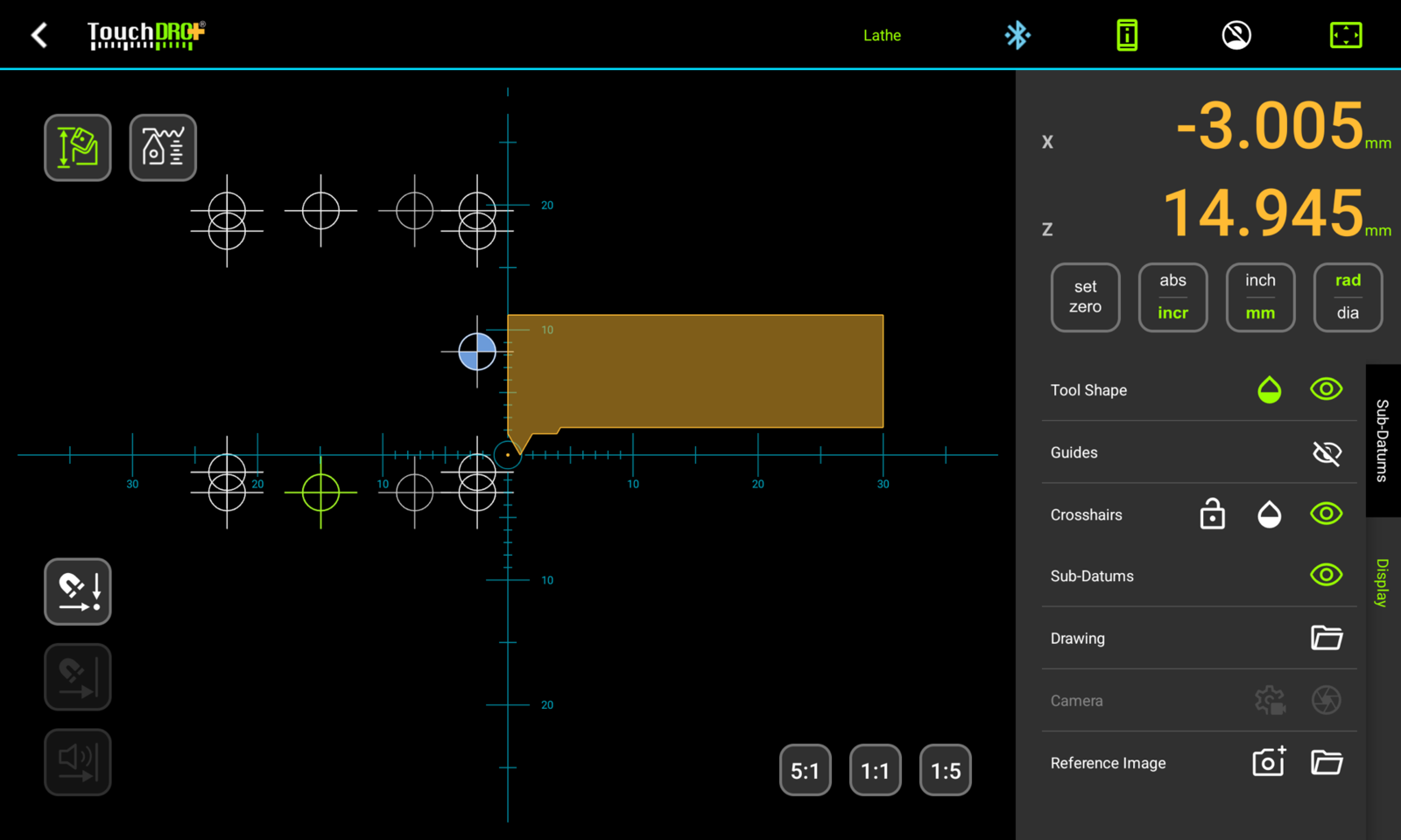
How the Cutter Is Drawn
A lathe tool without geometry is drawn in the graphical view as a small dot at the position of the tool tip. When the applied tool has an outline attached, TouchDRO will draw the outline under the dot as a filled shape, with the lines of the original drawing on top of the fill. The shape is drawn at its real size, so it follows the display scale when you zoom in and out.
The dot always marks the point the readout is tracking. TouchDRO positions the outline so that the origin of the drawing is on the dot. TouchDRO doesn't use the outline for any calculations. The offsets, the readout, and the functions work the same way with or without it.
Preparing the Drawing
You can draw the outline in any CAD program that exports DXF files. A simple 2D sketch of the tool as seen from above is all that is needed. Many insert and tool holder manufacturers publish DXF or STEP models of their tooling, and a top view from one of those is a good starting point.
TouchDRO displays the drawing exactly as it was drawn. It doesn't move, rotate, or mirror the drawing, so the origin and the orientation have to be correct in the file.
Origin
The origin of the drawing (the point where X and Y are both 0) has to be on the point of the tool that the X and Z offsets refer to. This is the same point you touch off with when you "program the tool offsets". For a threading tool, it is the tip of the V. For a turning tool with a nose radius, it is the imaginary sharp corner where the two touch-off directions meet, which is slightly outside the rounded nose.
If you place a point entity at the origin to mark it, TouchDRO will treat it as a marker and leave it out of the outline.
Orientation
Draw the tool the way it appears in the lathe graphical view: looking down at the machine, with the headstock on the left. The horizontal axis of the drawing runs along the Z axis of the lathe, and the vertical axis of the drawing runs along the cross slide. A boring bar or a turning tool that points at the headstock has its tip on the left side of the drawing and its shank going off to the right.
The "Cutter Type" setting of the tool doesn't flip the outline. A boring bar that cuts on the near side of the bore has to be drawn with its tip pointing toward the operator, which is down in the drawing, the way it is shown in Fig. 1.
Outline
TouchDRO fills the outline when it forms a closed shape. The outline can be made of lines, arcs, circles, polylines, ellipses, and splines, and it doesn't have to be a single polyline. Ends that are within 0.01 mm (0.0004″) of each other are joined automatically. Closed shapes inside the outline, such as the screw hole in an insert, are left unfilled.
An outline with a larger gap can still be attached, but TouchDRO will draw it as lines without the fill. If only a part of the drawing fails to close, that part will be missing from the filled shape.
It's best to keep the drawing simple. Text, dimensions, and hatching are not needed, and TouchDRO ignores text and dimensions when it reads the file. The outline is limited to 5,000 line segments after the curves are broken into short lines. An ordinary tool outline uses a small fraction of that, and a drawing that goes over the limit is usually a drawing of the whole part.
Units and Size
You can draw in millimeters or in inches. When the DXF file states its units, TouchDRO will use them. When it doesn't, TouchDRO will read the numbers as millimeters and tell you that it had to assume the units. If the size of the imported outline comes out wrong, you can correct the units while importing, with the "Drawn in" selector.
TouchDRO expects the larger dimension of the outline to be between 1 mm and 400 mm (roughly 0.04″ to 15.75″). An outline outside that range brings up a warning, since it usually means the units are wrong. There is no need to draw the whole length of a long shank. The part of the tool that goes near the workpiece is enough.
File Format
TouchDRO uses the same converter for cutter outlines that it uses for part drawings. It converts text (ASCII) DXF files from version R12 onward on the tablet, without an internet connection, up to 2 MB in size. For a file the tablet can't convert, TouchDRO will offer to send it to TouchDRO's online converter, and it will ask before sending anything. The details are covered in the "CAD Drawing Import" guide.
Attaching the Drawing to a Tool
The outline is attached from the "Add New Tool" or "Edit Tool" dialog of the lathe tool library. Copy the DXF file to the tablet, or to a cloud drive the tablet can reach, before you start.
- Select "Tool Library" from the application menu drawer. This will bring up the "Saved Tools" dialog.
- Tap the tool you want to add the outline to. This will open the "Edit Tool" dialog.
- Tap the folder button on the "Cutter Geometry" row and pick the DXF file. TouchDRO will convert the drawing and open the "Cutter Geometry Import" dialog.
- Check that the two blue lines cross on the cutting tip, and that the "Size" row shows the real size of the tool. If the size is off by a factor of 25.4, change the "Drawn in" selector.
- Press "Attach". The dialog will close, and the "Cutter Geometry" row will show a small picture of the outline.
- Press "Save" in the "Edit Tool" dialog. The outline is not stored until the tool is saved.
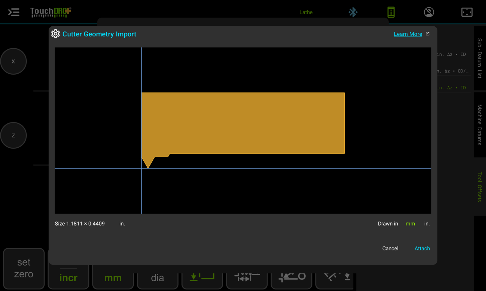
If TouchDRO finds a problem with the drawing, it will show a message above the picture. The messages, and the rest of the dialog, are described in the "Managing Tool Offsets on a Lathe" guide.
To see the cutter in the graphical view, apply the tool from the "Tool Offsets" panel or the "Tool Offset" dialog, the same way you would for any other tool. If the tool was already applied while you edited it, apply it again.
Dimming and Hiding the Cutter
A large tool can cover the sub-datums and guides you are trying to read. The "Tool Shape" row of the "Display panel" has two buttons for this. The half-opacity button switches the fill between a dimmed state, in which the drawing underneath shows through, and a more solid state. The eye button hides the shape altogether.
Dimming only affects the fill. The lines of the outline and the dot at the tool tip stay at full strength, so the cutting edge is easy to see in either state. The shape starts out dimmed, and TouchDRO remembers the setting for each machine profile.
Where the Geometry Is Stored
TouchDRO keeps the converted outline in the tool record, and it doesn't need the DXF file after the import. The outline is kept when a machine profile is duplicated, and it is removed when the tool is deleted.
The tool library CSV file doesn't include the geometry. When you move a tool library to another tablet with a CSV file, the offsets will come across, and the outlines have to be attached again from the DXF files.