TouchDRO Edge Finder Function
The "Indicate Workpiece" function (AKA the "Edge Finder") offers a convenient way to locate the edges or the center of a workpiece. The function can be used with an electronic edge finder connected to the TouchDRO adapter, or with a manual edge finding device.
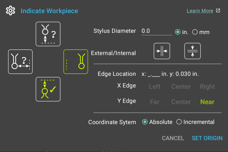
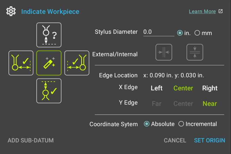
The function can be activated by the "Edge Finder" button from the function strip at the bottom of the main DRO display. When pressed, it brings up the "Indicate Workpiece" dialog, as shown below.
User Interface Overview

Edge Selector Buttons
The left side of the dialog contains the four edge selection buttons for the Left, Right, Front and Back edges that are used to tell the application which edge is being indicated.
If the "Electronic Edge Finder" setting is enabled in application preferences, each button has three states:
- Idle - the button is inactive and the edge has not been indicated
- Pressing the button will activate the scanning mode for the relevant edge. If any other edge was in the scanning mode, it will return back to the idle state
- Long-pressing the button will skip the scanning process and will use current spindle position to indicate the edge.
- Scanning - TouchDRO is waiting for electronic edge finder trigger to indicate the edge
- Pressing the button will deactivate the scanning mode and will return it to the Idle state.
- When the edge finder input is triggered, TouchDRO will record the position and switch to "Indicated" state. The edge can then be used to set the origin
- Indicated - the edge has been indicated and can be used to set the origin
- Long-pressing the button will clear the indicated position and return the button to Idle state
If the "Electronic Edge Finder" setting is disabled in application preferences, the Scanning state will be omitted. Pressing the button that is in Idle state will behave like a long-press described above.
Stylus Diameter
This is a required field that is used to tell TouchDRO the diameter of the edge finder stylus. The value is then used to automatically compensate for the radius offset when an edge is indicated.
This value is stored in the persistent state and will be pre-filled next time the dialog is opened to avoid unnecessary data entry.
Feature Type Selectors
Feature Type selector buttons determine whether an internal or external feature is being indicated.
Stylus Diameter Units Selectors
Stylus diameter units can be selected independent of the default units set in the application preferences.
Toggling between inches and millimeters will convert the value of the stylus diameter field to the selected units. The selection is not persisted and will default to the units selected in the application settings.
External/Internal Buttons
The two External/Internal buttons are used to toggle between external and internal edge modes. Their state will determine the directing of stylus diameter compensation.
Edge Location
The read-only Edge Location text box displays the location of the selected edge/center point in relation to the current absolute origin. The position is displayed for information purposes only and can not be edited directly.
X Axis Edge Selector Buttons
Immediately below the Origins text box are three toggle buttons that provide a way to select the relative location of the origin:
- When one of the edges is indicated, the corresponding button will be activated
- When both edges are indicated, all three buttons will be enabled and the "Center" button will be activated automatically
- Pressing any of the enabled buttons toggles it on and off
Y Edge Selector Buttons
These are analogous to the X Axis Edge Selector buttons.
Coordinate System Selector
When the "Indicate Workpiece" function is activated, it will default to the Absolute coordinate system. Coordinate system selector radio buttons provide a way to toggle between the Incremental and Absolute coordinate system as needed.
TouchDRO Plus Features

Auto Button
The "Auto" button (also called "Magic Wand" button) in the center of the Edge Selction buttons is available in TouchDRO Plus, and is used to automatically select the edge based on the direction of axis travel when the probe is triggered.
Note, that when the auto mode is enabled, External/Internal buttons are disabled.
Add Sub-Datum Button
The "Add Sub-Datum" button is available in TouchDRO Plus. It can be used to add the indicated edge as a sub-adtum coordinate. This button has two modes:
- Short press - adds current point to the sub-datum list, and clears the located edges.
- Long press - adds current point to the sub-datum list, but does not clear the located edges.
Working With Indicate Workpiece Function
Indicating Workpiece Edge With A Manual Edge Finder
Indicating one of the four edges of a workpiece consists of the following steps (using left edge as an example):
- Bring up the "Indicate Workpiece" function dialog
- If needed, enter the diameter of the probe tip (the value might already be present from previous function use)
- Move the spindle to the left of the workpiece and lower it as needed
- Move the spindle towards the left edge of the workpiece until the edge finder is triggered
- Long-press the left edge selector button; once TouchDRO emits a "long" beep, the button will switch to the "indicated" state
- TouchDRO will automatically activate the "Left" button for the X Axis Origin
- If desired, tap the "Incremental" radio button to set the incremental origin
- Press the "Set Origin" button
If desired, the origin for the second axis can be set at the same time by repeating steps 3-5 for the desired edge.
Indicating Workpiece Edge With A Touch Probe
The process of indicating the workpiece edge with an electronic touch probe is similar to the process described above and consists of the following steps:
- Bring up the "Indicate Workpiece" function dialog
- If needed, enter the diameter of the probe tip (the value might already be present from previous function use)
- Move the spindle to the left side of the workpiece
- Press the left edge selector button; the button will display "scanning" animation
- Slowly move the axis until the probe touches the left edge and is activated; the edge selector button will change to the "Indicated" state
- TouchDRO will automatically activate the "Left" button for the X Axis Origin
- If desired, tap the "Incremental" radio button to set the incremental origin
- Press the "Set Origin" button
Analogous process can be used to find any of the other three edges as needed.
Finding Centerline Of a Workpiece
- Bring up the "Indicate Workpiece" function dialog
- Edge finder tip diameter is irrelevant for the centerline. If a value is present, it does not need to be changed; otherwise 0 can be entered
- Move the spindle to the left side of the workpiece
- Indicate the left edge:
- If using an electronic edge finder:
- Press the left edge selector button; the button will display "scanning" animation
- Slowly move the axis until the probe touches the left edge and is activated; the edge selector button will change to the "Indicated" state
-
If using a manual edge finder:
- Move the edge finder towards the left edge of the part until the edge finder is triggered
- Long-press the left edge selector button
- If using an electronic edge finder:
- Repeat steps 3 and 4 for the right edge of the workpiece
- TouchDRO will automatically activate the "Center" button for the X Axis Origin
- If desired, tap the "Incremental" radio button to set the incremental origin
- Press the "Set Origin" button
Finding Center of A Hole
- Bring up the "Indicate Workpiece" function dialog
- Edge finder tip diameter is irrelevant. If a value is present, it does not need to be changed; otherwise 0 can be entered
- Move the spindle to the approximate center of the hole
- Indicate the left edge:
-
If using an electronic edge finder:
- Press the left edge selector button; the button will display "scanning" animation
- Slowly move the axis until the probe touches the left edge and is activated; the edge selector button will change to the "Indicated" state
- If using a manual edge finder:
- Move the edge finder towards the left edge of the part until the edge finder is triggered
- Long-press the left edge selector button
-
If using an electronic edge finder:
- Repeat steps 3 and 4 for the right edge of the workpiece
- TouchDRO will automatically activate the "Center" button for the X Axis Origin
- Repeat steps 3 and 6 for the Y axis
- TouchDRO will automatically activate the "Center" button for the Y Axis Origin
- If desired, tap the "Incremental" radio button to set the incremental origin
- Press the "Set Origin" button
Notes
Edge finder diameter field can't be left blank; TouchDRO will display an error and origin location selection buttons will not be activated. If the diameter is not needed (for example when locating a centerline of a part), simply enter "0" into the field. The value will be stored in the persistent application state and will be prefilled next time the dialog is opened.
Origin location selection buttons can be toggled on and off when they are enabled, so it's possible to turn all three buttons off. In such a case TouchDRO will not change the origin for that axis.
This dialog can be used to verify touch probe alignment. This can be done as follows:
- Enter edge finder diameter into the "Stylus Diameter" field
- Indicate the left edge (for example) using a reliable manual edge finder as described in the "Indicating Workpiece Edge With A Manual Edge Finder" section above
- Write down the value shown in the "X Axis Origin" text box
- Long-press the Left Edge selector button to clear the indicated position
- Orient the touch probe so the cable is facing away from you (at 12 o'clock position)
- Enter the probe tip diameter into the "Stylus Diameter" field
- Indicate the same edge using the electronic touch probe as described in the "Indicating Workpiece Edge With A Touch Probe"
- Note/write down the new X Origin Value
- Rotate the probe 90 degrees
- Repeat steps 7 and 8, rotate the probe by 90 degrees
- Repeat steps 7 and 8 again, rotate the probe by 90 degrees
- Repeat steps 7 and 8
At this point you will have five numbers - the position found by the edge finder and four positions found by rotating the probe. Ideally, all five numbers should be close to identical. If the positions differ by more than an acceptable tolerance, you will need to adjust and calibrate the probe to achieve better accuracy.
