
TouchDRO Initial Configuration
TouchDRO needs to know two things before the readouts mean anything: what kind of machine it is on, and what scales it is reading. This is the detail page for Steps 4 and 6 of the "TouchDRO Quick Start Guide". Pairing and connecting sit between these two halves and are covered there in Step 5.
Two TouchDRO builds are in use at the moment, and they keep these settings in different places, so this page has a section for each. The Play Store release, version 3.26.06, is configured from the "Settings" screen. The open beta, version 3.30.00 and later, is configured through a machine profile and the adapter. If TouchDRO asked you to create a machine profile the first time it started, you have the beta. The "TouchDRO V3" page explains how to join it.
TouchDRO 3.26.06 and Earlier
When you start the application for the first time, it will load default settings that are probably wrong for your machine. The settings live on the "Settings" screen, which opens from the application drawer menu. This section covers only the settings that need to change for the application to work correctly. If you plan to use TouchDRO with more than one machine, or on a combination machine such as a mill/lathe combo, start with the concept of "TouchDRO Configurations".
General Settings
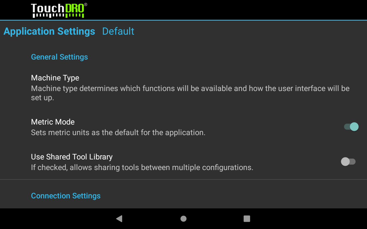
Machine type determines which functions are enabled, the format of the saved tool offset library, and the default projection in the graphical view and sub-datum memory.
When Metric Mode is enabled, TouchDRO will default to metric units throughout the application, including the sub-datum memory and some settings.
Use Shared Tool Library should be enabled if you are upgrading from TouchDRO V2.5. For a new installation, leave it off.
User Interface Settings
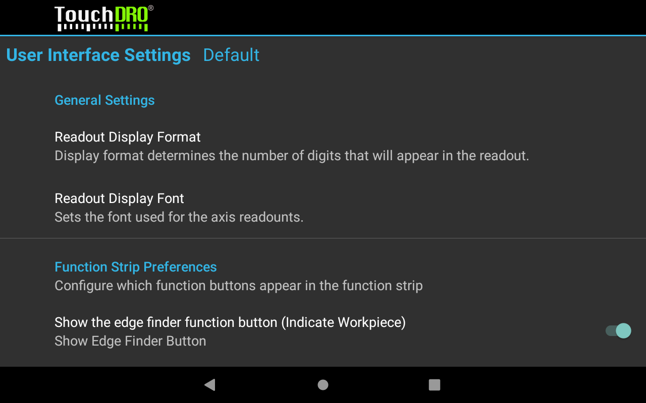
Readout Display Format determines how many digits are displayed after the decimal point. For glass and magnetic DRO scales, 0.0000 in/0.000 mm is recommended. For capacitive scales, 0.000 in/0.00 mm gives a more stable display.
Axis Settings (X, Y, Z)
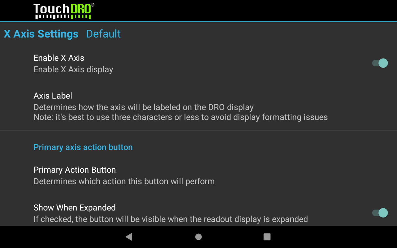
Axis settings configure the input parameters and the readout display for each axis. This is where TouchDRO is adapted to your specific machine. The full list is covered on the "Axis Settings" manual page.
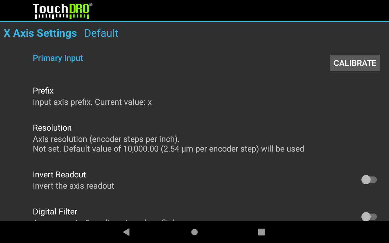
Note that by default, axis resolution is set to 10000 encoder counts per inch, which is unlikely to be the right value for your scales. To set the correct resolution, follow the "DRO Scale Calibration" guide once the scales are installed on the machine. For rough testing, the following starting points get the readout into the right ballpark:
- 5-micron glass and magnetic scales: 5080 counts per inch
- 1-micron glass and magnetic scales: 25400 counts per inch
- iGaging EZ-View and DigiMag scales: 2650 counts per inch
- Other capacitive scales: 2540 counts per inch
Below are the recommended initial settings for the common machine types.
Lathe
For most lathe setups, the following changes from the defaults are the common ones:
- Disable the Y axis. By convention, the long axis on a lathe is Z and the cross slide is X.
- Set the "Third Action Button" setting to the "Hold/Set Position" function.
- Enable the tachometer.
- If you are using an RPM sensor, set "Pulses Per Revolution" according to your encoder disk. Otherwise, set it to 0, which lets you enter the RPM directly on the main readout screen and still get the feed rate and cutting speed display.
Vertical Milling Machine
- The default configuration is sufficient for a milling machine with three scale inputs.
- If your mill has a separate quill movement, as on a knee mill and many imported bench-top machines, enable the "Secondary Input" and set its prefix to "w".
- For a two-axis setup with scales on the table only, disable the Z axis.
Horizontal Milling Machine
- For a three-axis setup, no changes from the defaults are needed.
- For a two-axis setup with scales on the table only, disable the Y axis.
Surface Grinder
- For a three-axis setup, no changes are needed.
- In most cases, the scales are on the column (Y axis) and on the front-to-back movement (Z axis). For such a setup, disable the X axis.
Combination Machine
- Use two separate "Configurations", one per spindle.
- Use the prefix setting to map the inputs to the correct outputs, so each spindle configuration uses the correct "coordinate system".
- Apply the suggestions above to each spindle configuration.
Next: with the settings in, crank each handle and check the readouts as described in Step 6 of the "Quick Start Guide", then run "DRO Scale Calibration" on each axis. The section below describes the open beta and does not apply to your version.
TouchDRO 3.30.00 and Later
The machine description lives in the machine profile, which TouchDRO asks you to create the first time it starts. The scale description is stored on the adapter itself and is set after connecting, so those settings follow the machine rather than the tablet.
The Machine Profile
A machine profile holds everything TouchDRO needs to know about one machine: the machine type, the default units, and which adapter input feeds which readout. The "New Machine Profile" dialog will open on the first start; to make another profile later, or to revisit one, see "Machine Profiles".
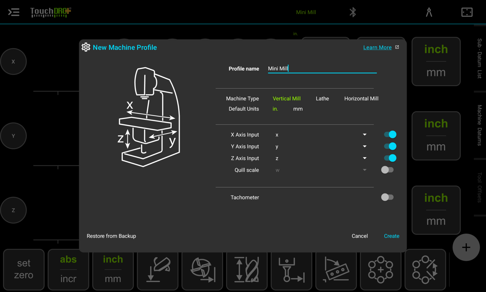
Name the profile after the machine, pick the machine type and your preferred units, and leave the axis inputs at their defaults unless you have a reason not to. The type does most of the work:
- Vertical Mill shows the X, Y, and Z readouts. If the machine has a separate quill scale, turn on the "Quill scale" input; TouchDRO will read it on the W input and can sum it with the knee travel into one Z reading.
- Lathe shows only the X (cross slide) and Z (carriage) readouts. Nothing needs to be disabled by hand.
- Horizontal Mill shows the standard three axes with the horizontal-mill conventions.
Turn on the "Tachometer" switch if you wired an RPM sensor to the adapter's auxiliary input. Everything in this dialog can be changed later, so a wrong guess costs nothing.
Adapter Settings
The scale settings live with the adapter, so the application has to be connected before you can reach them. To open the "DRO Adapter Details" dialog, tap the device-status button next to the connection icon at the top of the screen.
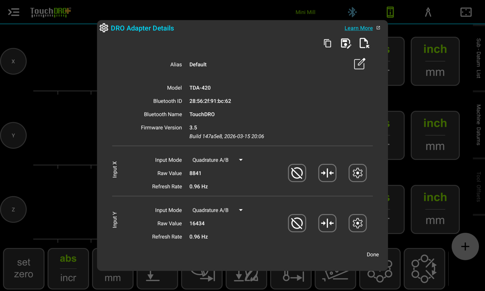
The top of the dialog identifies the adapter (model, Bluetooth name, firmware version). Below it, each scale input has its own block with three useful things at setup time:
- Input Mode sets the protocol for the scale wired to that input. "Quadrature A/B" is the default and is correct for glass and magnetic scales. A scale that connects through a converter needs the matching serial protocol instead: "iGaging 21 Bit" for EZ-View and DigiMag scales, "BIN6" for Shahe, and "Mitutoyo SPC" for both Mitutoyo Digimatic instruments and iGaging AbsoluteDRO Plus, which speaks the same protocol. Pick the mode, tap Save, then tap "Restart Now" in the orange banner. The change is not active until the adapter restarts, and until it is, that axis will not read at all. The "Adapter Details Dialog" page covers the dropdown and the restart in detail.
- Raw Value is the unscaled count coming from the scale. Move the axis by hand and the raw value will change; that is the quickest proof that a newly wired scale is alive, before any other setting is touched.
- The gear button opens that input's encoder settings, covered next.
Encoder Settings
Each input's "Encoder Settings" dialog describes the scale itself: what kind of encoder it is, how fine it counts, and which way it counts. For a typical linear scale, three settings matter at setup time and the rest can stay at their defaults.
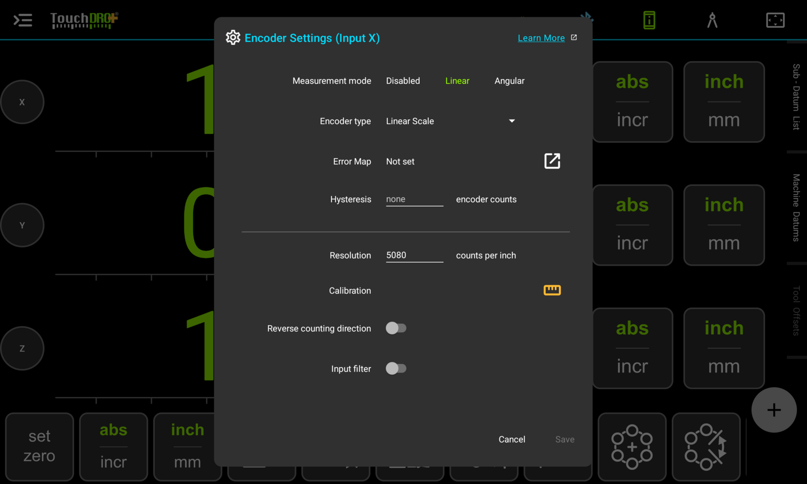
- Measurement mode stays on "Linear" for ordinary DRO scales. "Angular" is for rotary encoders.
- Resolution is the scale's count density. As a starting point:
- 5-micron glass and magnetic scales: 5080 counts per inch
- 1-micron glass and magnetic scales: 25400 counts per inch
- iGaging EZ-View and DigiMag scales: 2650 counts per inch
- Other capacitive scales: 2540 counts per inch
- Reverse counting direction flips which way the number grows. If a readout counts backward for your machine's convention, this switch fixes it; no rewiring is involved.
The remaining settings (hysteresis, error map, input filter) are covered on the "Encoder Settings" manual page and are not needed to get a machine running.
Checking the Readouts
With the profile created and each input configured, crank every handle on the machine and watch the screen:
- Each handle should move its own readout. If a different readout moves, either swap the two scale plugs at the adapter or change the axis input assignments in the machine profile.
- Each readout should count the right way. If not, toggle "Reverse counting direction" for that input.
- A measured move should roughly match the screen. Once it does, run "DRO Scale Calibration" on each axis to make the numbers exact.
The settings are stored with the adapter, so this is a one-time job per machine. From here, pick up the "Quick Start Guide" at the practice project, or go straight to work.