
Encoder Settings
When you mount a DRO scale or an encoder onto your machine and connect it to the TouchDRO adapter, the scale, your machine, and the adapter become a tightly coupled measurement instrument. To achieve the maximum possible accuracy, the setup needs to be configured and calibrated together.
The settings for each scale are part of the adapter profile. They include the resolution, the error correction and backlash compensation maps, and a few other things that are intrinsic to the particular scale or encoder. TouchDRO keeps them in the "Encoder Settings (Input X)" dialog, one per adapter input.
Opening the Dialog
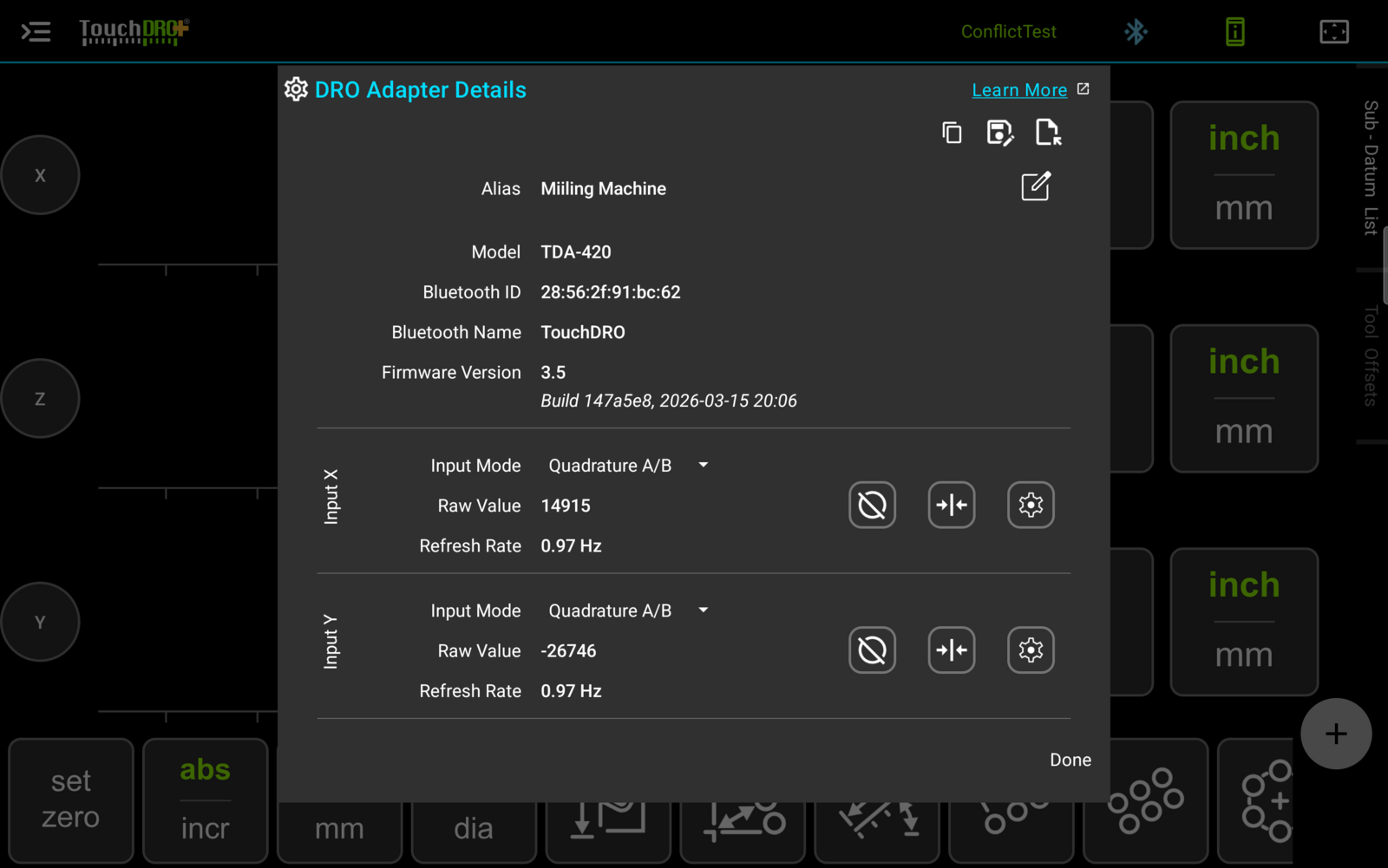
The settings are reached through the adapter, since that is where they are stored. Either way you get there, the route runs through the "DRO Adapter Details" dialog, and you open an input's settings with the gear button on its block.
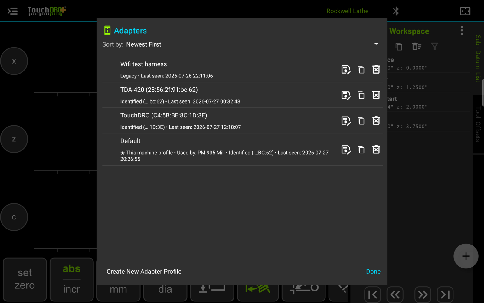
To reach the adapter you are connected to, press the device-status button next to the connection icon at the top of the screen. To reach any adapter TouchDRO knows about, whether or not it is connected, open "Adapter Profiles" from the application menu and press the one you want.
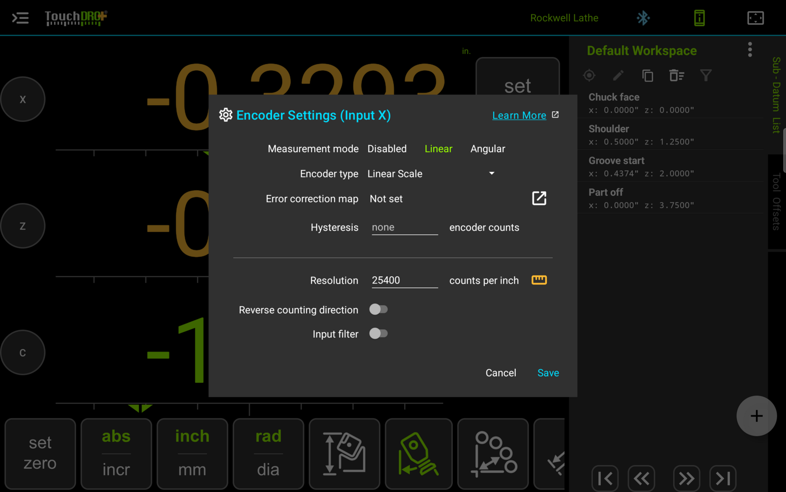
The fields below are described in the order the dialog lists them. Which fields appear at all depends on the encoder type, so that is the one to settle first even though it is the second row down.
Measurement Mode
Sets whether the input is read as a linear position, as an angle, or not at all. The three options are "Disabled", "Linear", and "Angular".
"Linear" is for a device that measures travel: a scale, or an encoder on a leadscrew or rack. "Angular" is for an encoder that measures rotation directly. "Disabled" turns the input off.
What the choice drives is the Calibration Wizard and a few parts of the user interface. An angular input changes the unit on "Resolution" from "counts per inch" to "counts per rev", and the wizard samples two positions a fixed number of revolutions apart instead of measuring a block. Little else depends on it.
An axis pointed at a disabled input stops receiving position. Its readout will not update, any velocity it reports will be zero, and functions that need a live position on that axis, 3D probing among them, may not work.
Encoder Type
It's important to set the correct encoder type. TouchDRO uses it to decide which of the remaining fields are shown, and in particular whether the input is corrected for hysteresis or for backlash.
Those two are opposite corrections. Hysteresis adds counts when the direction changes, and backlash ignores them, because in one case the readout lags the machine and in the other it leads. The same number entered against the wrong one moves the readout the wrong way and makes the error larger rather than smaller, so the type matters more than the amount.
| Type | What it is |
|---|---|
| "Linear Scale" | Glass, magnetic, or capacitive scale on the axis |
| "Leadscrew Encoder" | Rotary encoder on a leadscrew or worm |
| "Rotary Encoder" | Mounted directly on the axis or spindle |
| "Rack & Pinion" | Rotary encoder driven by a rack |
Counts per Screw Rev
Shown for "Leadscrew Encoder" only. The number of encoder counts in one turn of the screw.
This is not the number most encoder documentation quotes. A datasheet usually gives the count of slits in the disk, which is the number of full quadrature periods in one revolution. TouchDRO reads every transition, and two quadrature channels produce four transitions per period, so the figure this field wants is four times the quoted one. An encoder listed at 600 produces 2400 counts per revolution.
If the encoder is driven through gears or a pulley rather than sitting on the screw itself, the drive ratio has to be accounted for as well. Multiply by the number of turns the encoder makes for one turn of the screw. What the field wants is the count at the screw, not at the encoder.
TouchDRO uses the figure to sanity-check the backlash you enter against it. A backlash of a full turn of the screw or more is more lost motion than the thread has, so TouchDRO will say so rather than accept it quietly.
Error Correction Map
A scale's error is rarely uniform along its length, and calibrating the resolution corrects only the average. An error correction map corrects the scale interval by interval: it is a list of positions, each with a signed correction in encoder counts, and TouchDRO interpolates linearly between them.
The "Error Map" row summarizes the stored map as the range it covers, "4 intervals (0 – 400)", or shows "Not set" when the input has none. The button on the row opens the map editor. The maps themselves, the editor, the "Error Map Wizard" that builds a map by measuring the scale against a reference, and the file format for importing one are all covered in the "Error Correction and Backlash Maps" page.
Hysteresis
Hysteresis is a dead zone on a change of direction: the table is already moving, but the readout hasn't started to change yet. It shows up in optical and sometimes magnetic scales, and most commonly in rack and pinion setups, where lash in the rack delays the encoder.
To correct it, enter the size of the dead zone in encoder counts. TouchDRO adds that value whenever it detects a change in direction.
To measure it, set a plunger-type dial test indicator against the axis and move the axis in one direction. Zero both the DRO and the indicator, then move back the other way and note the difference between the two readings. Zero both again, reverse again, and repeat a few times, since one reading on its own will not be representative. Multiply the average of those differences by the input's resolution to get the figure in encoder counts, which is what the field wants.
Backlash Compensation
Backlash is the opposite problem, and it is common wherever an encoder is fitted to a leadscrew. The encoder starts counting as soon as the screw turns, while the table is still standing still and the nut is taking up the lash. The readout moves before the machine does.
To correct it, enter the lost motion in encoder counts. TouchDRO ignores that many counts after a change of direction.
The setting offers "None", "Constant", and "Map". "Constant" applies one figure across the whole travel and is available on every edition.
Backlash Map
A worn leadscrew doesn't have one backlash figure. It has more where the screw has done most of its work and less at the ends, so a single constant is a compromise everywhere. A backlash map holds a separate figure for each interval, and TouchDRO applies whichever one matches the current position.
Selecting "Map" adds a "Backlash map" row to the dialog, which summarizes the stored map the way the "Error Map" row does and opens the same style of editor. Backlash maps are a TouchDRO Plus feature, and they are covered alongside error correction maps in the "Error Correction and Backlash Maps" page.
Both kinds of map are indexed by the encoder's own count, so a mapped axis has to be re-homed at a repeatable position after every restart. The "Establishing a Repeatable Home Position" section of that page covers how.
Resolution
The number of counts the encoder produces per unit of travel, shown as "counts per inch" for a linear input and "counts per rev" for an angular one. It can be typed in directly when the figure is known, or measured with the Calibration Wizard using the ruler button beside the field.
The ruler button is color coded: amber while the input has not been calibrated, and green once it has. It is the quickest way to see which inputs still need doing.
Reverse Counting Direction
Inverts the direction the input counts, for a scale mounted so that it reads backwards. Calibration sets this on its own, so it rarely needs touching by hand.
This is the adapter's direction setting and it affects every machine profile that reads the input. Each axis also has its own invert setting in the axis settings, which applies to one profile only.
Input Filter
Smooths the signal arriving on the input. It is there for home-built adapters, the Arduino and MSP430 designs that read iGaging scales directly, where the raw signal needs conditioning before it can be counted reliably.
Leave it switched off on any current TouchDRO adapter. That hardware conditions the scale signal itself, before the reading reaches the application, so the filter has nothing left to do.