
Workspace Commands
The most useful sub-datum operations are right in front of you: adding, activating, and editing points takes a tap or two on the sub-datum panel or the graphical view. More commands hide in the second-level menus, reached by long-pressing a point in the "Graphical View display" or through the sub-datum panel's menu button. These commands see the most use during job setup, when a stored workspace needs to be lined up with the part that is actually on the machine.
The commands work at three levels: a single sub-datum, a pair of sub-datums, or the workspace as a whole. A single point can become the origin or carry the whole workspace to the spindle; a pair measures and aligns by two features at once; the workspace-wide commands rotate, flip, and scale the stored geometry.
Sub-Datum Commands
The single-point commands live in the "Sub-Datum Commands" dialog. To open it, long-press a sub-datum in the "Graphical View display". Every command asks for confirmation, and the confirmation states exactly what is about to happen before anything is applied.
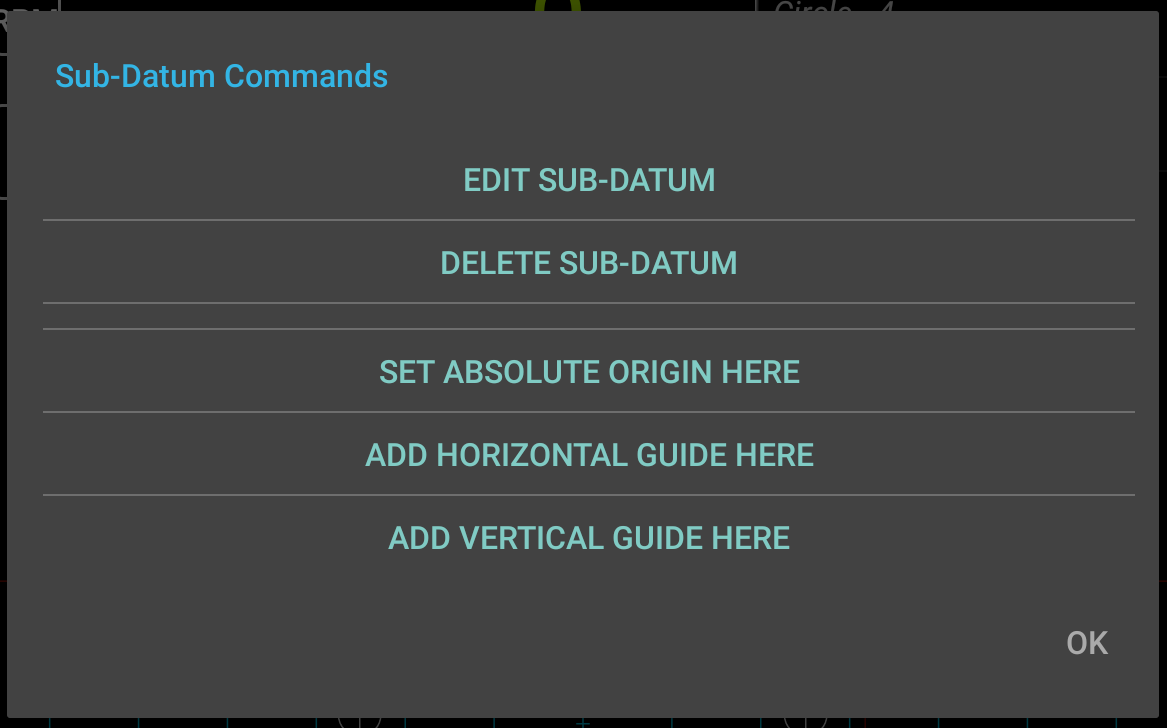
Align Absolute Origin to Sub-Datum
Normally, when you select a sub-datum, it turns into a temporary origin, but there might be cases when you need to make it the absolute origin. The "Align Absolute Origin to Sub-Datum" command does just that: it makes the selected sub-datum the absolute origin. This is useful when the workspace was drawn from a different reference than the one indicated on the part. It is also a convenient way to hand a workspace to the next operation, renumbered from the feature that operation will indicate.
Align Sub-Datum to Spindle
"Align Sub-Datum to Spindle", or "Align Sub-Datum to Tool" on a lathe, moves the whole workspace so the pressed point lands at the current position. The command is useful when the origin can't be indicated. For example, you might get a drawing where the datum is outside of the stock, or the part is too large to reach the origin. It is also the first step in aligning a crooked part to the machine axes. In a nutshell, the command allows you to indicate the workpiece by an arbitrary feature, rather than its origin.
On a lathe, the dialog adds two axis-specific versions: "Align Sub-Datum to Tool (Z Only)" and "Align Sub-Datum to Tool (X Only)". When turning, you often establish the Z axis with a facing cut and the X axis with a light cleanup cut; the per-axis commands let each cut align its own axis independently.
The most common use case is aligning a profile drawing to the part. Profile drawings conventionally put zero on the left end of the part; after facing, align the point that marks the right-most feature of the profile to the fresh face, and the whole profile sits where the material actually is.
Sub-Datum Pair Commands
The pair commands take two points: tap the first sub-datum to activate it, then long-press the second. The "Sub-Datum Pair Commands" dialog will open, with the active point as "A" and the pressed point as "B". The top of the dialog shows the axis differences, the straight-line distance, and the angle of the line between the two points, so the dialog is useful for measuring even when no command is taken.
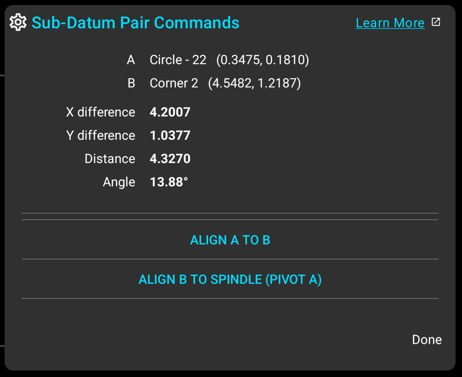
On a lathe, the readouts are in the Z/X plane, and the angle between two points of a profile is the taper angle, ready to transfer to the "Compound Slide Angle Compensation" function or to the compound's scale.
Align A to B
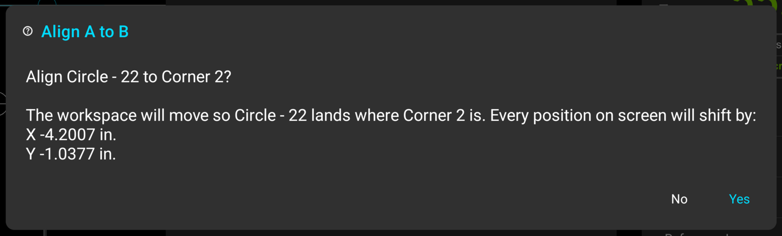
"Align A to B" moves the workspace so point A lands where point B is. This is the stored-point version of aligning to the spindle. A common use for this command is aligning a drawing to a hole or bore center. For example, you might use the "Indicate Workpiece" function to find the hole center and add it as a temporary sub-datum. Then you can tap the workspace's matching point ("A"), long-press the captured one ("B"), and apply the command. TouchDRO will calculate the necessary shift and move the workspace so the drawing's hole center lines up with the real one.
Align B to Spindle (Pivot A)
"Align B to Spindle (Pivot A)" rotates the workspace about point A until point B lines up with the spindle. Together with "Align Sub-Datum to Spindle", it aligns a workspace to a part that can't be mounted square, using two known features. The features don't need to be machined ones; two scratch marks scribed at known drawing locations work. The alignment takes two steps:
- Pick up the first feature and align it to the spindle: position the spindle over it, long-press its workspace point, and choose "Align Sub-Datum to Spindle". The workspace now has the right position and the wrong angle.
- Tap that same point to activate it; it becomes "A", the pivot. Move the spindle over the second feature, long-press its workspace point ("B"), and choose "Align B to Spindle (Pivot A)". The workspace will rotate about A until B lines up with the spindle.
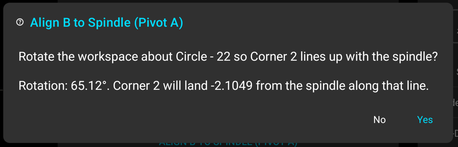
The confirmation states the rotation and one more number worth reading: how far B will land from the spindle along the line after the rotation. That residual is the quality of the alignment in one number. Near zero means the two features are where the drawing says they are; a large residual means the wrong feature was picked up, step one was skipped, or the part isn't the size the drawing claims.
"Align B to Spindle (Pivot A)" is a TouchDRO Plus feature, available on milling machine profiles. If the workspace has guides, the rotation raises the same "Guides Will Be Deleted" choice as the "Rotate Workspace" command, described below.
The Workspace Commands Menu
The rotate, flip, and scale commands live in the "Workspace Commands" menu, opened with the menu ("⋮") button in the upper-right corner of the sub-datum panel, alongside the origin command above, the "CSV import and export" commands, and "Export to DXF File". The three geometry commands touch only the current workspace; "machine datums" are stored with the machine profile and never move.
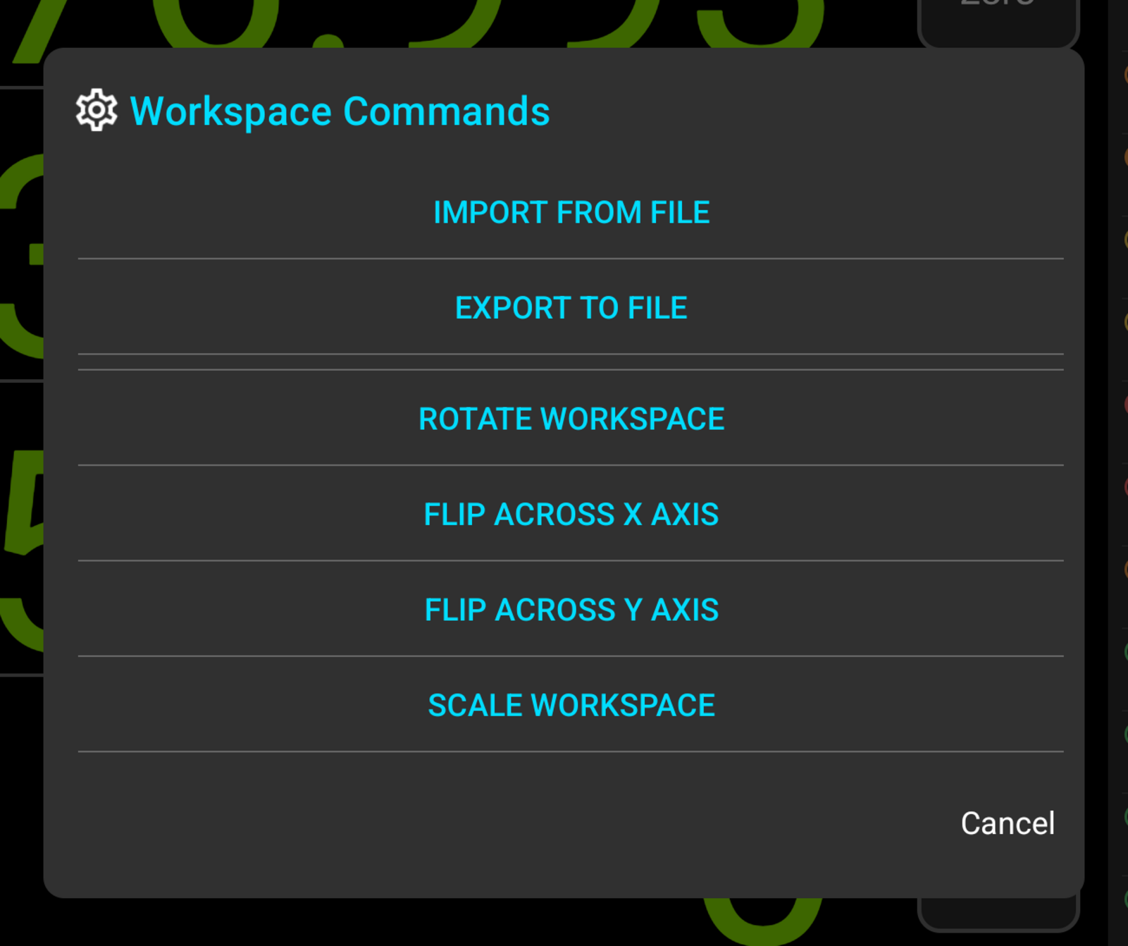
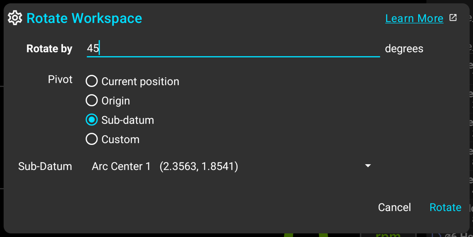
The three dialogs share the same layout. Each has an amount field at the top and an anchor below it: the pivot for rotating and scaling, or the flip line for flipping. The anchor is the part of the workspace that stays put, and it comes from one of four sources:
- "Current position" anchors the command at the spindle's current location
- "Origin" anchors it at the workspace's absolute origin
- "Sub-datum" anchors it at a stored point, selected from a list
- "Custom" anchors it at typed-in coordinates; the fields are calculator fields, and the two-arrow sync button next to each copies in the current axis reading
Rotating a Workspace
The "Rotate Workspace" command turns every stored coordinate about a pivot point by an entered angle. It is the manual counterpart to "Align B to Spindle (Pivot A)": that command measures the part and computes the rotation, while "Rotate Workspace" is for when the angle is already known, from the drawing, a sine bar, or a measured feature.
To rotate a workspace, choose "Rotate Workspace" from the menu, enter the angle in degrees into the "Rotate by" field, select the "Pivot", and press "Rotate". TouchDRO will turn every stored coordinate about the pivot; the pivot itself is the one point that will stay where it is.
Rotation and Guides
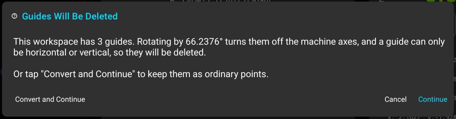
Quarter turns, 90, 180, or 270 degrees, keep every "guide" a guide: a horizontal guide comes out horizontal or vertical, at exactly the remapped position. Any other angle would tilt the guides off the machine axes, and a guide can only be horizontal or vertical. Before an odd-angle rotation is applied, TouchDRO therefore shows the "Guides Will Be Deleted" confirmation. Continuing deletes the guides; "Convert and Continue" keeps each one as an ordinary one-axis point instead.
Flipping a Workspace
The flip commands mirror the workspace across a horizontal or vertical line. This is useful for mirror-image work: the left-hand version of a bracket that was laid out as a right-hand part, for example, or the mating half of an asymmetric joint. Instead of laying the mirrored part out again, flip the workspace and machine the second part from the same coordinates.
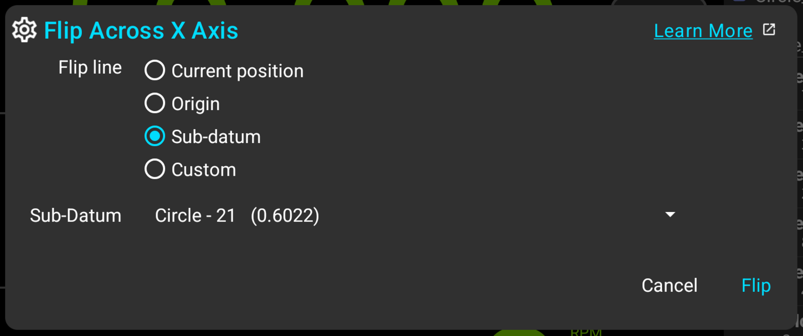
There are two flip commands, "Flip Across X Axis" and "Flip Across Y Axis", one for each mirror direction. The "Flip line" selection places the line the geometry is mirrored across. The four anchor sources work as described above, with a single coordinate, since a flip line only needs one.
Scaling a Workspace
The "Scale Workspace" command resizes the whole workspace by a percentage. This is useful when the geometry is the right shape at the wrong size: an "imported drawing" that measures a few percent off the actual stock, a layout traced from a photo, or a part that needs to be made oversize for a shrink fit. Instead of correcting the drawing and importing it again, scale the workspace in place.
The "Scale by" field takes a percentage: 100 is no change, and 120 makes everything a fifth bigger. The field is a calculator field, so the measure-and-correct case needs no arithmetic on your part. If the drawing says 50 mm and the part measures 50.8, enter "50.8/50*100" and press "Scale". The scale is applied about the "Pivot", which is the one point that keeps its coordinates.
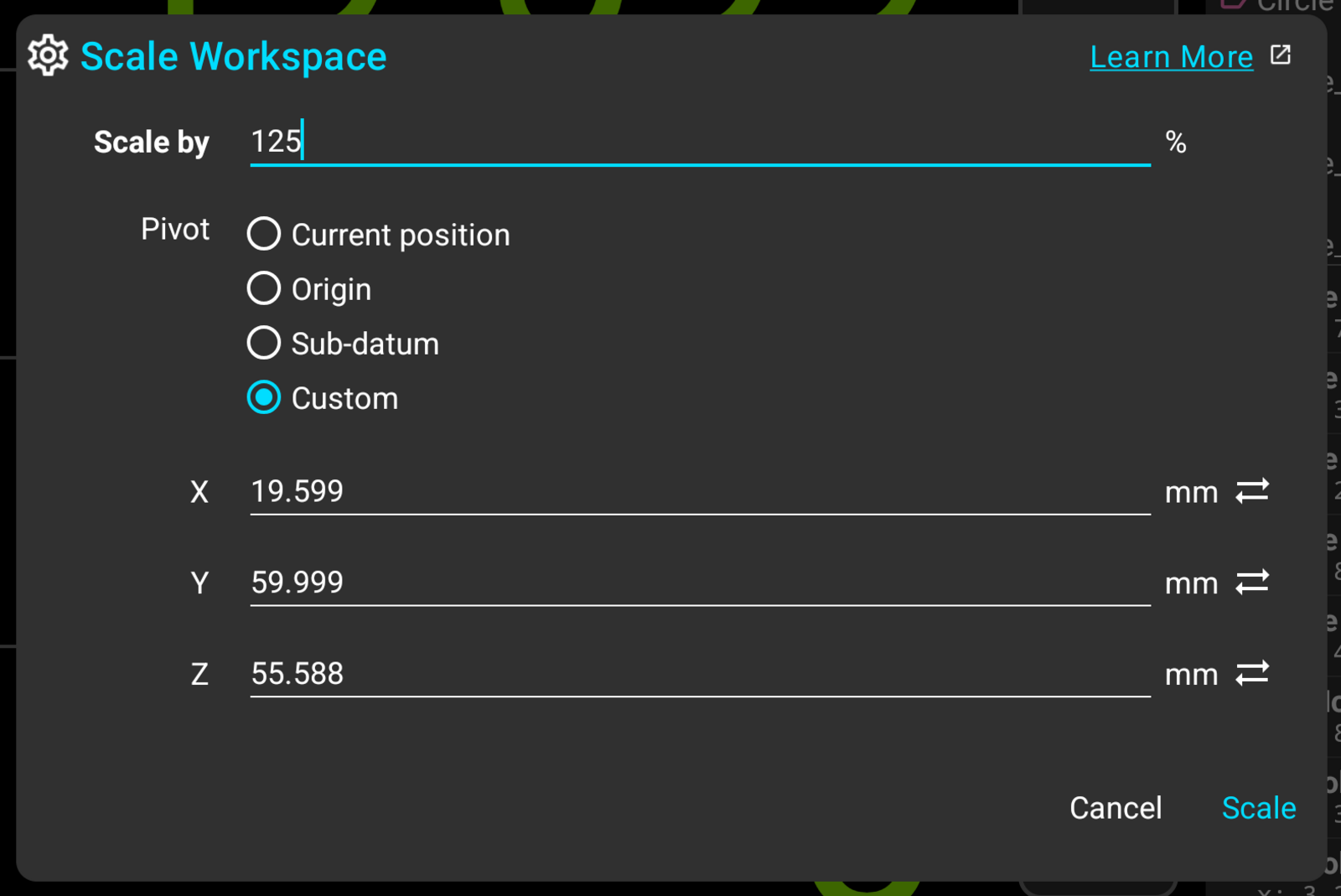
The scale is uniform in all three axes: stored Z values scale together with X and Y, which is why the custom pivot has three fields. If the workspace carries Z depths measured from a tool reference, re-check them after scaling.