
Compound Slide Angle Compensation
With the compound slide parallel or square to the bed, its travel lines up with one of the main axes and following it is easy. Set the compound over at an angle, and every turn of its handwheel moves the tool partly along the bed and partly across it. The compound's own readout still shows distance along the slide, but the X and Z readouts know nothing about that movement. The displayed position stops matching the tool.
The "Compound Slide Angle Compensation" function corrects this. Given the compound's angle, TouchDRO splits compound travel into its cross slide and carriage components. Each component is added to the matching readout, so X and Z keep tracking the tool while the compound is in use.
This is the lathe half of a feature pair. On a milling profile the "Mill Head Tilt/Nod Compensation" function does the same job, correcting the X, Y, and Z readouts when the head is leaned over.
Enabling the Function
Vectoring is switched on per machine profile, on the "Auxiliary Readout Settings" screen. The settings there gate one another, so work down the screen in order:
- Switch on "Enable Auxiliary Readout"
- Set "Axis Type" to "Compound slide"
- Switch on "Enable Vectoring"; this setting only appears once the axis type is set to "Compound slide"
- Set "Compound Zero Position" to match your machine, as described in the next section
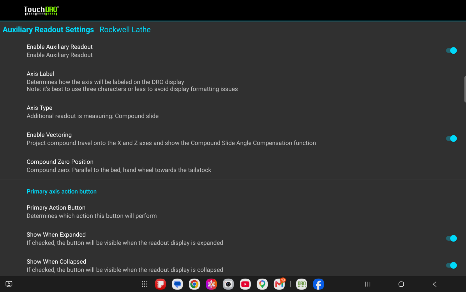
If the function's button still doesn't appear in the function strip, check these three things:
- "Enable Auxiliary Readout" and "Enable Vectoring" are both switched on
- "Axis Type" is set to "Compound slide"
- The compound's input is not also assigned to the X or Z axis
The last condition hides the function entirely rather than graying it out, and for good reason. If the compound's input also fed X, arming the function would make X count the same scale twice: once as its own input and once more through the projection. The axis would still read, still zero, and still probe; it would just be wrong by an amount that depends on the angle. Hiding the function turns an input assignment mistake into "the function is unavailable" instead of a readout that lies.
Compound Zero Position
Lathes don't agree on where the compound's protractor reads zero. The "Compound Zero Position" setting tells TouchDRO which convention your machine uses. A reference is two things, not one: where zero sits, and which way the numbers grow from it. Both change between conventions. A compound reading 29.5 degrees on a headstock-zeroed protractor points toward the headstock; the same number on a tailstock-zeroed protractor points toward the tailstock.
To open the picker, press the setting. It offers exactly three options, worded as machine setups rather than as angles:
- "Parallel to the bed, hand wheel towards the tailstock" - the default
- "Square to the bed, hand wheel towards the operator"
- "Parallel to the bed, hand wheel towards the headstock" - typical of South Bend lathes and their clones
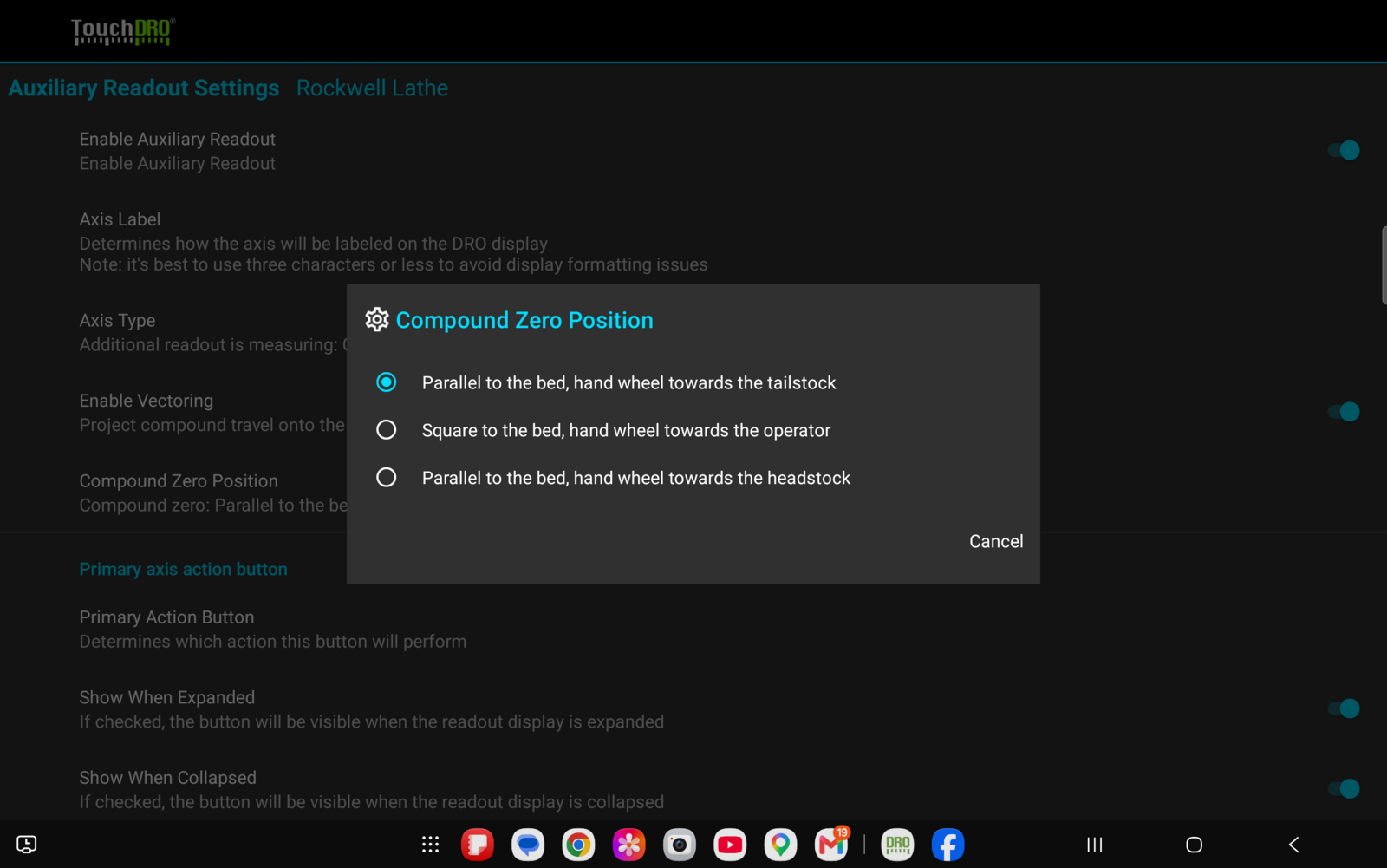
The picker commits as soon as an option is pressed; there is no OK button, only "Cancel". These three are the only choices, and there is no way to enter a custom zero angle. The selected convention is echoed in the settings summary as "Compound zero:" followed by the option's name.
User Interface Overview
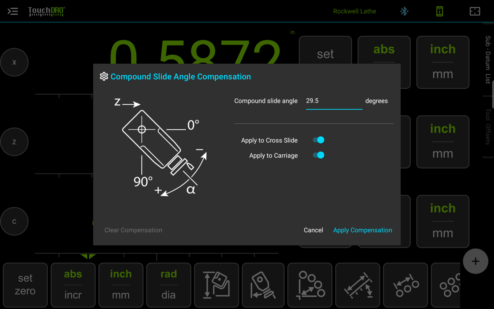
The dialog has a single angle field, "Compound slide angle", which accepts any value between -180 and +180 degrees. One angle fully describes the compound's setting, so unlike the milling function there is no combined validation. The bounds simply cover the swivel's full travel.
The field accepts simple arithmetic as well as plain numbers; entering "45/2", for instance, produces 22.50 degrees. Trigonometric functions are not available, so an expression like "sin(30)" will not evaluate.
The two toggles are named for the machine parts they feed. "Apply to Cross Slide" controls the component projected onto the X readout, and "Apply to Carriage" controls the component projected onto the Z readout. Both are switched on by default.
The "Apply Compensation" button arms the function with the entered angle, and the "Cancel" button closes the dialog without changing anything. The "Clear Compensation" button switches the function off; it stays disabled until the function is armed.
Applying Compensation
Enter the compound's angle as read from your machine's protractor, check the toggles, and press "Apply Compensation". The compensation takes effect the instant the button is pressed. The readouts repaint immediately rather than waiting for the next scale reading.
What Amber and Green Mean
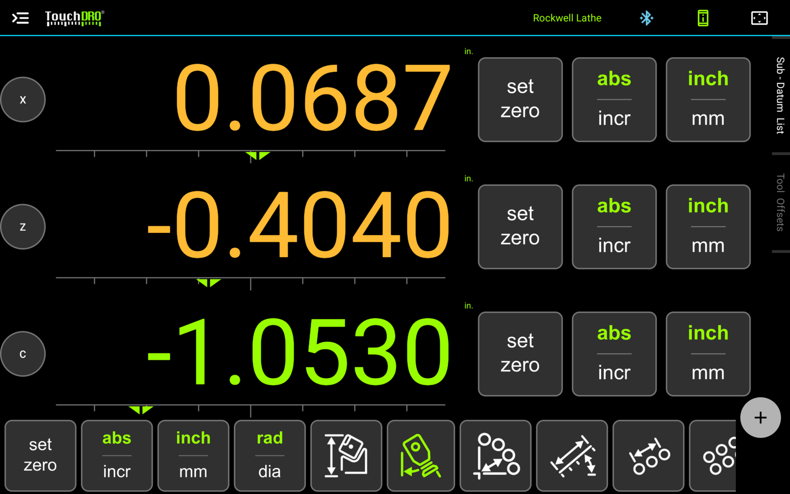
Fig. 4 shows the state after applying. The function's icon is lit green, the X and Z readouts have turned amber, and the compound's own readout is still green. Each color answers a different question. The green icon means the function is armed; an amber readout means that axis's displayed position is actually being shifted by the projection.
The compound's readout stays green because the compound is the source of the projection, not a recipient. Its own position is not adjusted, only projected onto the other two axes. Likewise, arming the function with "Apply to Carriage" switched off leaves Z reading its raw position, so Z would stay green while X turns amber.
Amber never merely echoes a switch; it lights only when the number on the screen is being adjusted, which is what makes it worth trusting.
Clearing Compensation
To switch the function off, reopen the dialog and press "Clear Compensation". TouchDRO will ask for confirmation and then return the X and Z readouts to their raw readings.