
CAD Drawing Import
Drawing import lets TouchDRO display a CAD drawing directly in the graphical view, at true scale. The crosshairs show where the spindle is on the drawing in real time, so instead of constantly reading dimensions off a print, you machine while looking at the part itself.
For one-off parts, complicated pockets, or drawings covered in hole coordinates, this feels much like working from layout lines, except this layout is always accurate, never wears off, and moves with the DRO.
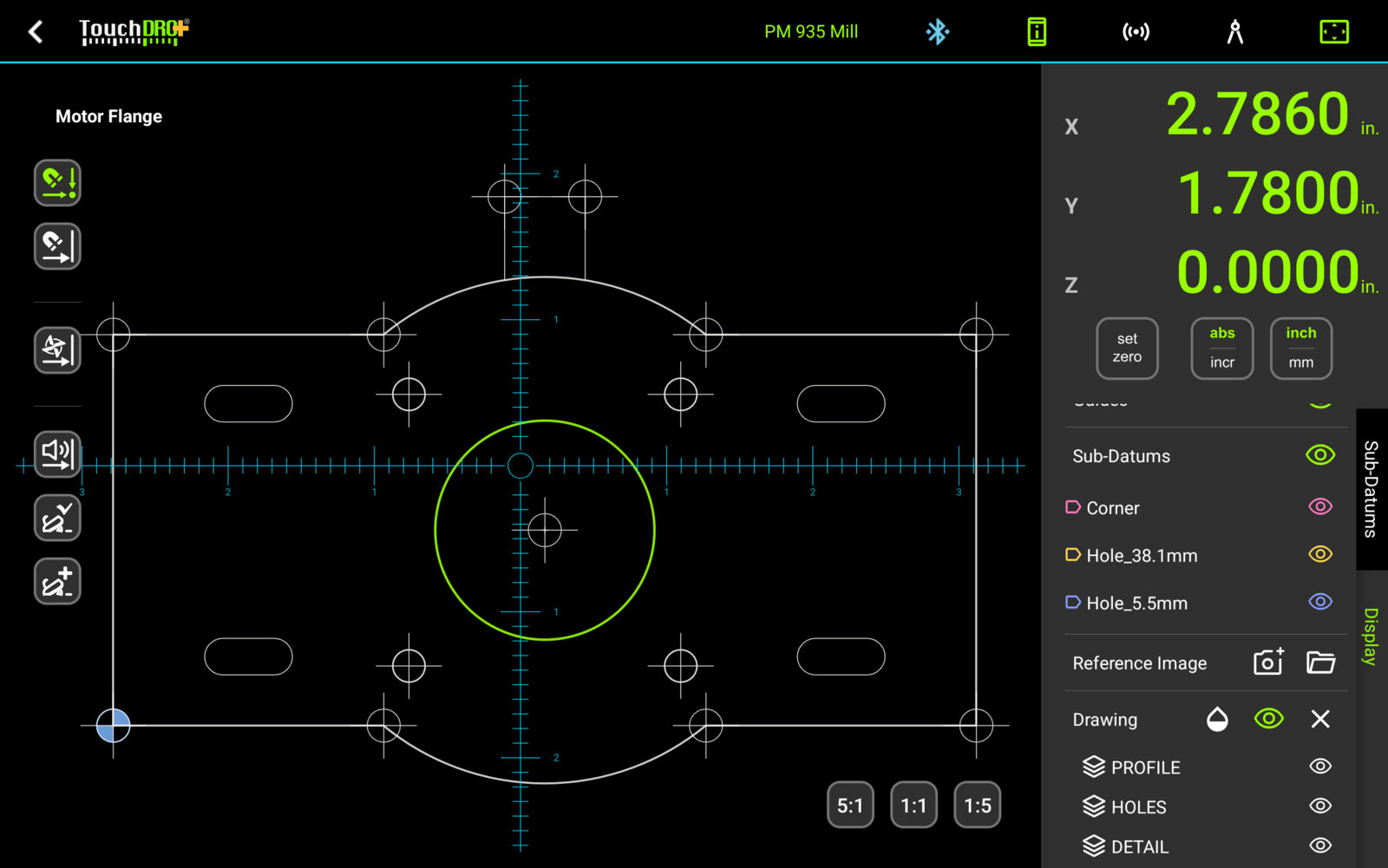
TouchDRO can also extract the drawing's hole centers, arc centers, and corners as sub-datums, tagged by group, so every important location is a tap away, and a pattern with several hole sizes can be worked one drill size at a time. You can import a DXF file from any CAD program that exports one, or export a drawing from SnapCAD straight to TouchDRO.
Drawing Files
TouchDRO imports drawings from DXF files, which Fusion, FreeCAD, AutoCAD, and nearly every other CAD program can export. TouchDRO converts the file on the tablet itself, so importing a drawing doesn't need an internet connection.
TouchDRO imports the geometry in a DXF file: lines, arcs, circles, polylines, splines, ellipses, the outlines of hatched areas, and blocks, which are expanded in place. Splines and ellipses are approximated by curves that stay within 1 µm of the original. Text and dimensions are annotations rather than geometry, so they are left out, along with leaders, images, and 3D objects such as solids and meshes.
If you draw in SnapCAD, you can skip the DXF file altogether. SnapCAD has a built-in "Export to TouchDRO" command that writes the drawing in TouchDRO's own file format, with the geometry already converted, so TouchDRO doesn't need to interpret a DXF file at all. This is the simplest way to import a drawing from SnapCAD. The full path from SnapCAD to the machine is covered in the "Machining to a CAD Drawing" guide.
On a lathe, TouchDRO uses the same converter to attach a DXF outline of the cutter to a tool in the tool library, as described in the "Lathe Cutter Geometry" guide.
Because the coordinates are true scale, a drawing needs no scaling or calibration step on import. This is the main difference between a drawing and a reference photo, which carries no scale of its own and has to be calibrated against known points, as described in the "Reference Image Overlay" guide.
Loading a Drawing
A workspace holds one drawing at a time. The entry point is the "Drawing" row of the "Display" panel in the graphical view, described in the "Graphical View Display" guide. To load a drawing, tap the folder button on that row; this will open the system file picker.
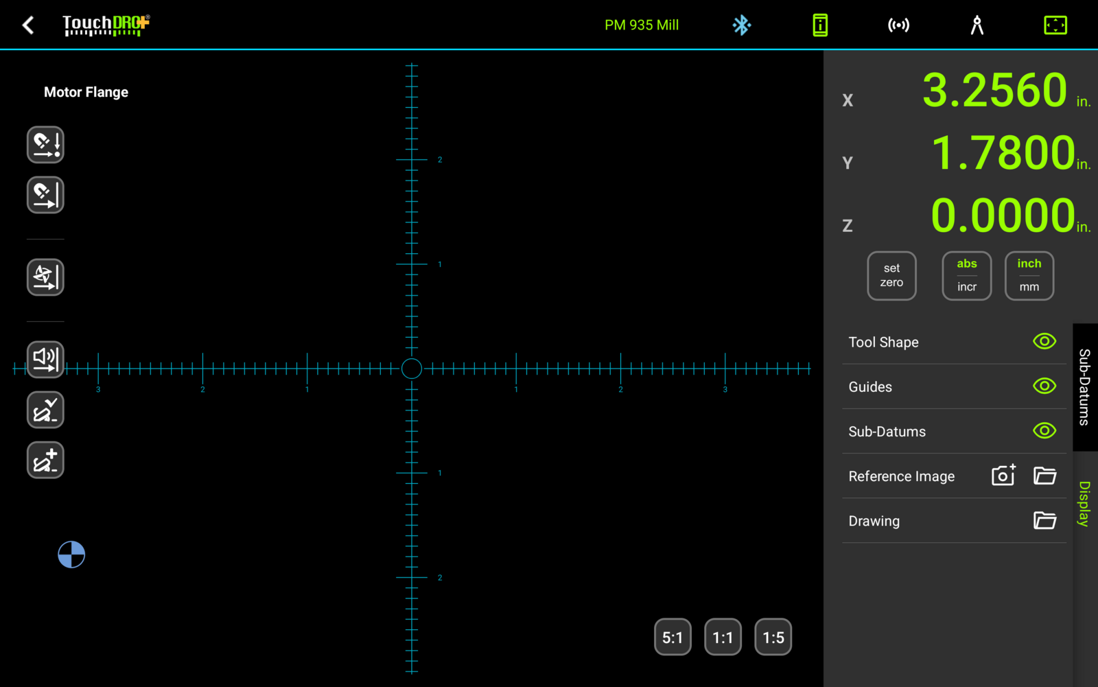
The file picker lists every file rather than only drawings, because other apps label DXF files in several different ways. TouchDRO checks the contents of the file you pick, whatever its name, and reports a file that is neither a DXF file nor a TouchDRO drawing with "This file isn't a drawing TouchDRO can open."
TouchDRO converts a DXF file first, as described in the next section. A file exported from SnapCAD opens the "Set Up Drawing" dialog directly. If that file is damaged, TouchDRO will report "TouchDRO couldn't import this drawing." in the "Drawing Not Imported" dialog instead. Its "Technical details" section lists the problems found in the file, and the workspace is left untouched.
Converting a DXF Drawing
TouchDRO converts a DXF file into its own drawing format before the drawing can be placed, and it converts most files in well under a second. If the conversion takes longer, TouchDRO will show the "Converting Drawing" dialog while it reads and converts the file. To abandon the import, tap "Cancel". When the conversion finishes, the "Set Up Drawing" dialog will open, and from there you set up a DXF drawing the same way as one exported from SnapCAD.
Sending a Drawing to the Online Converter
Some DXF files contain features the tablet can't process, such as a binary DXF file, a very long polyline, or a drawing that takes too long to convert on the tablet. TouchDRO's online converter handles more DXF features, so for a file like this, TouchDRO will offer to send it there. TouchDRO asks every time, and nothing is sent unless you tap "Send".
TouchDRO won't offer to send a file that breaks one of the hard limits, such as a file larger than 2 MB or with more than 10,000 parts, because the online converter has the same limits. Before asking, TouchDRO also checks that the tablet is connected to the internet and that sending is allowed in Settings. If either check fails, TouchDRO will explain why in the "Drawing Not Converted" dialog, described under "When a Drawing Doesn't Import" below.
Otherwise, the "Convert Drawing Online?" dialog will open, naming the file and asking whether to upload it. The dialog holds the following controls:
- The "Share this drawing with TouchDRO to help improve the converter built into the app." checkbox starts unticked every time. If you tick it, a copy of the drawing is kept to improve conversion on the tablet, as described below.
- "Learn More" expands a short explanation of what happens to the file after it is uploaded.
- "Technical details" expands the converter's own notes on what the tablet couldn't process. The notes are meant for troubleshooting, so if you ask for help with the drawing, include them along with the file.
- "Send" uploads the file. "Cancel" closes the dialog without importing or sending anything.
After you tap "Send", the "Converting Drawing" dialog will return while the file is uploaded and converted. This usually takes a few seconds, and TouchDRO will stop waiting after about a minute. You can tap "Cancel" at any point, and nothing more will be sent. When the online conversion succeeds, the "Set Up Drawing" dialog will open as usual.
TouchDRO keeps a copy of each drawing the online converter returns, so if you import the same file again, the "Set Up Drawing" dialog will open directly, without asking or uploading anything. TouchDRO removes the oldest copies over time. To remove them all at once, tap "Clear cache" on TouchDRO's page in the Android "Apps" settings.
What Is Sent and Kept
When you tap "Send", TouchDRO uploads the drawing file along with two identifiers: an install ID, which is a random code TouchDRO generates on the tablet, and the ID of the adapter used by the current machine profile, if it has one. Neither identifier includes your name or email address, and no account is involved. TouchDRO's online converter processes the file automatically, without anyone looking at it, and deletes the uploaded drawing within two days.
The server keeps one log entry per conversion for five years. The entry holds the two identifiers, the file's size, whether the conversion succeeded, how long it took, and the name of the CAD program that wrote the file. It doesn't contain the drawing itself or its layer names.
If you tick the share checkbox, a copy of that one drawing is kept indefinitely. It is used only to improve the converter built into TouchDRO, so that fewer drawings need to be sent online, and it is never shared with anyone else. With the checkbox unticked, no copy is kept.
A drawing TouchDRO converts on the tablet is never sent. The full details are in the "TouchDRO Privacy Policy".
Turning Off Online Conversion
If you don't want TouchDRO to send drawings off the tablet at all, turn on "Never send anything to TouchDRO's servers" in the "Privacy" section of the "Settings" screen, described in the "Application Settings" guide. With the switch on, TouchDRO still imports every DXF file the tablet can convert. For a file that needs the online converter, TouchDRO will skip the "Convert Drawing Online?" dialog and report that the switch is on.
When a Drawing Doesn't Import
TouchDRO reports a DXF file it can't import in the "Drawing Not Converted" dialog. The dialog gives the reason in one sentence, and where there is more to say, its "Technical details" section holds the converter's own notes. The dialog offers a "Retry" button when trying again can help, and only a "Done" button otherwise.
The messages below are grouped by what you can do about them.
Problems with the File
These messages mean the file has to change before TouchDRO can import it. Trying again won't help, and TouchDRO won't offer to send these files to the online converter.
- "The file couldn't be read." TouchDRO couldn't open or copy the file you picked.
- "This file isn't a drawing TouchDRO can open." The file's contents are neither a DXF drawing nor a TouchDRO drawing, regardless of its name.
- "This drawing is too large for TouchDRO (over 2 MB)."
- "This drawing has too many lines and curves to import." The drawing holds more than 10,000 of them.
- "This drawing's blocks are nested too deeply to import." The drawing has blocks inside blocks, too many levels deep. Exploding the nested blocks in your CAD program before exporting will reduce the nesting.
- "This drawing's coordinates are too far from zero for TouchDRO." Part of the drawing lies too far from its origin. Moving the geometry closer to the origin in your CAD program will fix this.
- "TouchDRO didn't find any lines, arcs or curves to import in this drawing." The file was converted, but it holds nothing TouchDRO imports, such as a drawing made only of text and dimensions. "Technical details" lists what was left out.
You can usually bring a drawing that is too large, or holds too many lines and curves, under the limits by exporting only the geometry you need at the machine and leaving out title blocks, hatching, and other views.
Problems Reaching the Online Converter
These messages mean the tablet couldn't convert the drawing, and TouchDRO couldn't use the online converter or didn't get an answer in time.
- "This drawing needs TouchDRO's online converter, and this tablet isn't connected to the internet." Connect the tablet to the internet and tap "Retry". TouchDRO will then ask before sending the file.
- "This drawing needs TouchDRO's online converter, and "Never send anything to TouchDRO's servers" is turned on in Settings." To send this drawing, turn the switch off as described above, then import the file again.
- "Converting a drawing online requires an internet connection." The connection dropped during the upload. Tap "Retry" once the tablet is back online.
- "The online conversion took too long. Please try again." Tap "Retry". The online converter keeps its result for a short time, so a second try is usually quick.
- "The online converter finished, but TouchDRO couldn't collect the result in time. Please try again." The result expired before the tablet downloaded it. Tap "Retry".
- "The online converter's answer couldn't be read. Please try again." The download was damaged. Tap "Retry".
- "TouchDRO's online converter is busy right now. Please try again later." Wait a while, then import the file again.
- "TouchDRO couldn't reach the online converter. This will be fixed in an update." The online converter turned the request away, which is a defect in the app rather than a problem with your drawing. Trying again won't help.
- "TouchDRO couldn't reach the online converter. If this Wi-Fi network needs a sign-in page, sign in and try again." Some Wi-Fi networks show a sign-in page before they allow internet access, and that page intercepted the upload. Sign in to the network, then tap "Retry".
Drawings Neither Converter Can Process
- "Neither this tablet nor TouchDRO's online converter could process this drawing. Try exporting it again from your CAD program." "Technical details" lists the online converter's reasons.
- "TouchDRO's online converter doesn't handle this kind of file." The online converter rejected the file's format, for example because the file isn't a DXF file after all.
- "The drawing couldn't be sent." The online converter rejected the request.
If you have SnapCAD, one way around this is to open the DXF file in SnapCAD and export it with "Export to TouchDRO", since TouchDRO doesn't need to convert the exported file. If you ask for help with a drawing that won't import, include the file and the text from "Technical details".
The Set Up Drawing Dialog
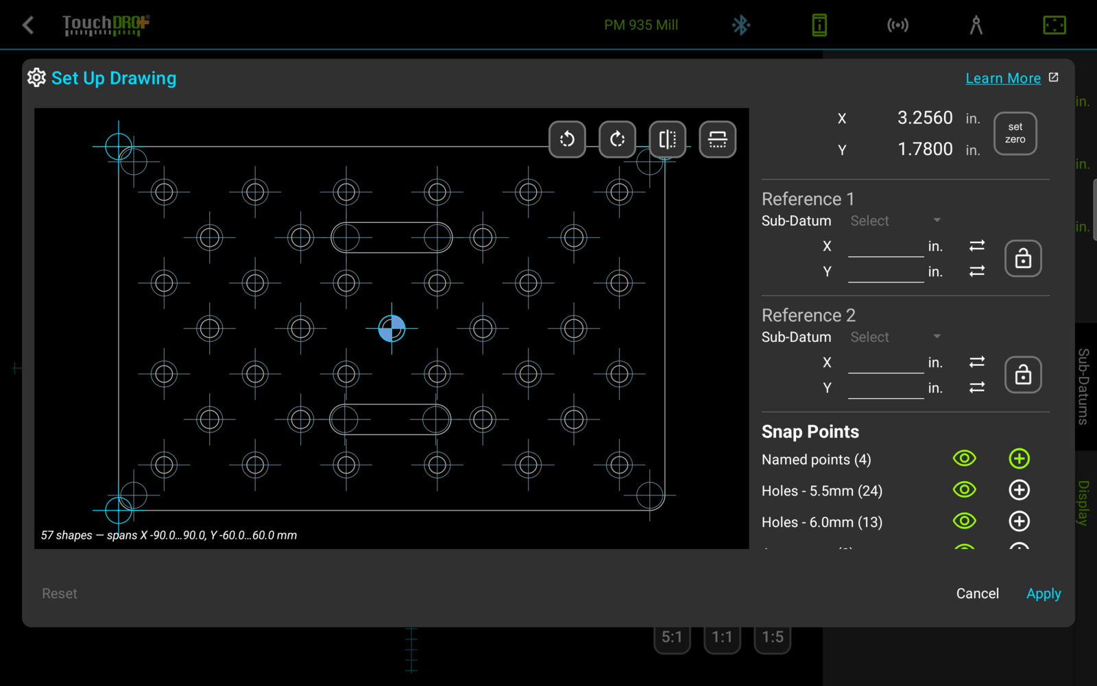
The "Set Up Drawing" dialog is where the drawing is positioned against the workpiece and its features are selected. Since the drawing carries true scale, it arrives already placed: the dialog opens with the drawing fitted to the preview, a datum mark on the point that will land on the workspace origin, and "Apply" available immediately. Everything else in the dialog is optional refinement.
Drawing Preview
The preview occupies the left side of the dialog and shows the drawing, the datum mark, and the snap points of every visible group. It responds to the same gestures as the graphical view: drag to pan, pinch to zoom, and double-tap to fit the drawing to the window.
Four buttons along the top of the preview change the drawing's orientation. Rotate left and rotate right turn it in 90-degree steps, and the two mirror buttons flip it horizontally or vertically.
To select a feature, tap it in the preview. The selection is marked on the preview and named on the status line. To clear it, tap the selected feature again, or tap an empty area of the preview. Only features belonging to a visible group can be selected, so a group whose eye is switched off in the "Snap Points" panel is not selectable either.
Position Readout
The Position Readout at the top of the control panel shows the current spindle or tool position for the two axes shown in the graphical view, along with a "set zero" button that zeroes both. It's there so a machine coordinate can be read, or an origin set, without leaving the dialog.
Reference Points
A reference point ties one feature in the drawing to one coordinate on the machine. Both "Reference 1" and "Reference 2" are optional, and each serves a different purpose.
Each section holds the same controls: a "Sub-Datum" selector, an X and a Y field, a synchronize button beside each field, and a lock button. The fields take the machine coordinate that the selected feature should sit at. The synchronize buttons copy the current position of that axis into the field, and the "Sub-Datum" selector fills both fields from a stored coordinate. The lock button accepts the reference. Once locked, it becomes a clear button that releases that reference and leaves the other one untouched.
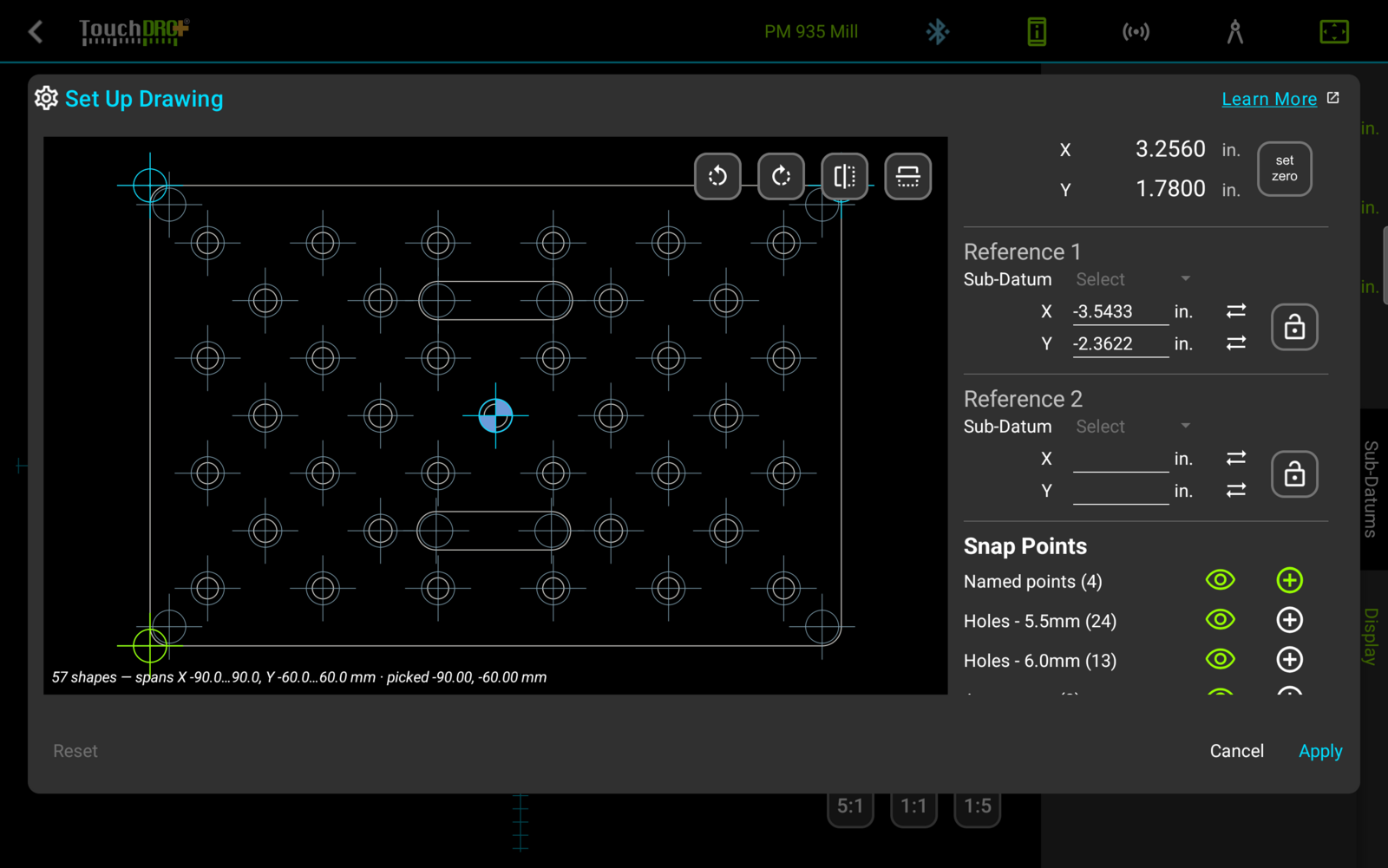
"Reference 1" moves the drawing so that the selected feature sits at the stated coordinate. Its purpose is to put the drawing's origin somewhere convenient, which matters when the file was drawn around an origin that isn't practical to work from at the machine.
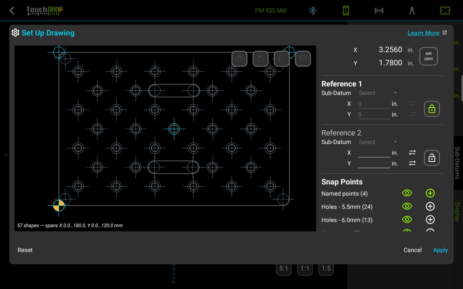
"Reference 2" is a sanity check on scale. TouchDRO compares the distance between the two referenced features on the machine against the same distance in the drawing, and reports a disagreement rather than stretching the drawing to fit. A plain mismatch is stated on a banner at the top of the dialog, in the form "These points are 2.40 mm further apart on the machine than in the drawing." A mismatch that lands on one of the common unit errors is named instead, along with what will be done about it: "Based on the two points you selected, this drawing is in inches, not millimeters. Apply will scale it ×25.4 to match." The conversion is carried out by "Apply", so a diagnosis that looks wrong can be overruled by correcting or clearing a reference point.
Two locked reference points also set the drawing's angle. TouchDRO takes the angle implied by the two stated coordinates, reports it on the status line, and rotates the drawing by that angle when it is applied. An angle too small to be distinguished from the precision of the two picks is treated as zero, and picking the two features further apart is what makes a small angle measurable.
Snap Points
The "Snap Points" panel lists the features TouchDRO found in the drawing, grouped by kind: points named in the CAD file, hole centers grouped by diameter, arc centers, and corners. Each row names its group and the number of features in it, such as "Holes - 6.0mm (13)". A group with no features in it is left out of the panel.
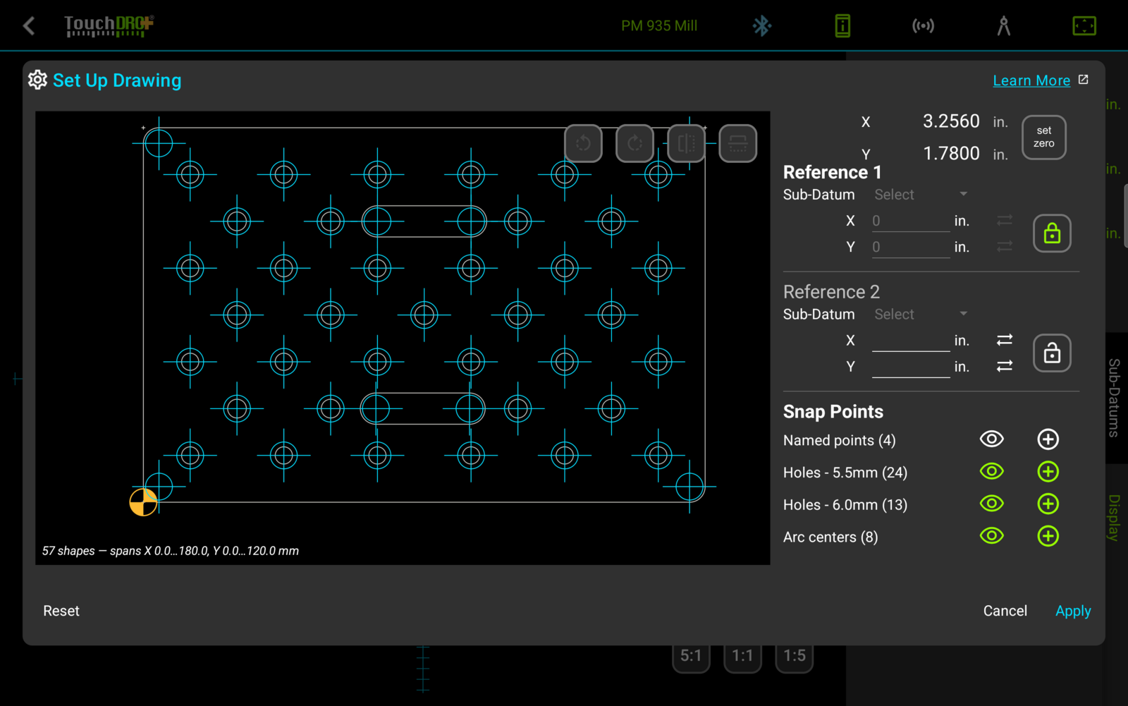
Each row carries two toggles, and they answer independent questions:
- The eye, "Show on drawing", controls whether the group is drawn on the preview. Since only visible features can be selected, it also controls whether the group can be used as a reference point.
- The circled plus, "Create as sub-datums", marks the whole group to be turned into sub-datums when the drawing is applied. A group is created in full or not at all.
The markers are useful on their own. A drawing shows a hole as its outline, while the machining happens at the center, and the snap point puts a visible mark exactly there. The same goes for arcs, whose centers lie away from the curve itself, with nothing else in the drawing to mark them.
Every group starts visible, except a corners group large enough to clutter the preview, which starts hidden. Only named points start marked for creation, since a named point is the one candidate a person placed in the drawing deliberately; every derived group starts unmarked, so nothing is created unless you ask for it.
Status Line
The status line below the preview reports what was loaded and what has happened since. It always states the number of shapes in the drawing and the overall area they span in machine coordinates, which is also the quickest check that a file arrived at the scale you expected. Three further notes are appended as they apply: the coordinate of the feature last selected, the angle set by the reference points, and any warning raised while reading the file, such as a lathe drawing loaded into a milling machine workspace.
Reset, Cancel, and Apply
"Reset" returns the drawing to the state it was in when the file was loaded, discarding the placement, orientation, and both reference points, so the setup can be started over without reopening the file. "Cancel" discards the import entirely. "Apply" stores the drawing in the workspace, creates sub-datums from every group marked with the circled plus, and carries out any unit conversion the dialog diagnosed.
Extracted Sub-Datums
Sub-datums created by "Apply" are named after their kind and numbered, in the form "6mm Hole 1", "6mm Hole 2", and so on. Each group is given its own tag, such as "Hole_6mm" or "Arc_Center", so hole centers of different diameters remain separately filterable instead of arriving as one undifferentiated set. A second import into the same workspace appends "_2" to a tag already in use, the same way the pattern functions do. Tags and the filtering they support are covered in the "Sub-Datum Tags and Filtering" guide.
Once created, these are ordinary sub-datums. They can be edited, retagged, and deleted like any other, and they are not removed when the drawing they came from is cleared.
The Drawing in the Workspace
An imported drawing becomes a layer of the graphical view, drawn beneath the sub-datums and the tool position. The "Drawing" row of the "Display" panel carries three controls in place of the folder button: the eye shows or hides the drawing, the half-opacity button dims it so the sub-datums and cutter stay legible against it, and the clear button removes it from the workspace after a confirmation.
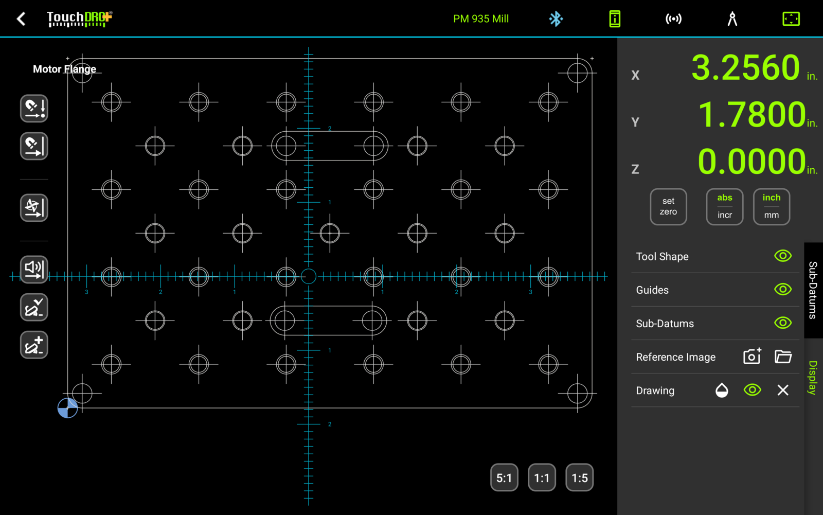
The drawing's shapes are selectable. To make a shape stand out, tap it; the selected shape is drawn brighter than the rest of the drawing, like the circle in Fig. 1. The selection is only visual at this time, but it is a convenient way to mark the feature being machined.
A drawing that carries more than one layer lists them under the "Drawing" row, each with its own eye, so construction geometry or a reference-only layer can be hidden while the rest of the drawing stays up. The "Sub-Datums" row expands the same way, one row per tag. Both are described in the "Graphical View Display" guide.

How to Use
To import a drawing, follow these steps:
- Open the "Display" panel and tap the folder button on the "Drawing" row
- Select the DXF file, or the file exported from SnapCAD, in the system file picker
- If the drawing's own origin isn't in a convenient spot, tap a feature in the preview, enter the machine coordinate it should sit at under "Reference 1", and press the lock button
- Switch on the circled plus for every "Snap Points" group you want stored as sub-datums
- Tap the "Apply" button
To use the drawing purely as a virtual layout, skip the "Snap Points" step and dim the drawing to half opacity once it's applied. The outline, slots, and hole positions are then visible in true position under the crosshairs, and you can mill to the drawing's lines the way you would mill to scribed layout lines.
Sometimes the drawing is square to its own frame, but the part on the machine isn't: a casting, or a workpiece held by its one flat surface, often sits at an angle to the table. In that case, use both reference points to align the drawing to the part:
- Tap the first feature, enter the position where it actually sits on the machine, and lock it
- Tap a second feature as far away from the first one as the part allows, enter its actual position, and lock it
- Review the angle reported on the status line, then tap the "Apply" button
The drawing is rotated to match, so the stored geometry describes the part as it is clamped rather than as it was drafted. Note that two points close together can't resolve a small angle; the further apart the two features are, the more accurate the alignment.
For a complete worked example, from the CAD export to the finished part, refer to the "Machining to a CAD Drawing" guide.