
Thread Cutting on a Lathe
Single-point threading is one of the more stressful operations on a manual lathe. The carriage moves under power toward a shoulder, and you have to disengage the half nuts at the same spot on every pass. At the same time, you need to keep track of the depth over a dozen or so passes. Furthermore, the thread is usually one of the last operations on the part, so a mistake can scrap hours of work.
Internal threads are even harder. Once the threading bar is inside the bore, you can't see the tool, the relief groove, or the bottom of a blind hole, so you have to rely on the dials and a mark on the bar.
TouchDRO provides a way to set the thread up ahead of time, so that during the cut the readout and the graphical view show you where the tool is in relation to the thread. You pick the thread from a list, the same way it is called out on the print, and TouchDRO lays it out in the workspace. As a result, the end of the thread, the relief groove, and the finished depth become positions you can see on the screen. While you cut, the X readout shows the distance to the finished depth of the thread, and the Z readout shows the distance to the end of the thread, so the near-zero warning can be used as an audible cue to disengage the half nuts. In addition, the thread cutting card shows whether the tool is in the cut or clear of the thread, which is especially useful inside a bore.
How Thread Cutting Works
Thread cutting is one feature that is used in two steps, and each step has its own button:
- First, you describe the thread in the "Thread Cutting" dialog, which is opened from the function strip of the main display. TouchDRO will calculate the diameters and store the thread in the current workspace as a set of guides and sub-datums.
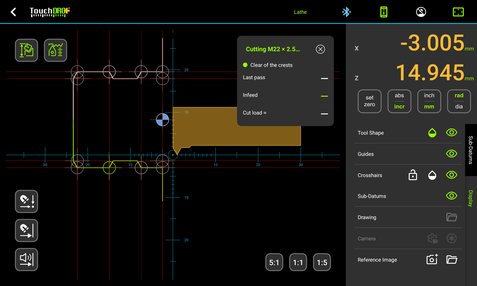
- Second, you arm the thread with the "Arm thread cutting" button in the graphical view. TouchDRO will draw the thread profile and show the thread cutting card. The readouts will show the distance to the root of the thread and to the end of the thread while you cut.
The two steps depend on each other. Setting a thread up doesn't change how the readout behaves until the thread is armed, and there is nothing to arm until a thread has been set up. For this reason, if you tap "Arm thread cutting" in a workspace that has no threads, TouchDRO will offer to open the "Thread Cutting" dialog. A thread stays in the workspace once it's set up, so you can set up all the threads for a part ahead of time and arm each one when you get to it. Both icons are shown in the "DRO Function Buttons" legend.
TouchDRO supports 60-degree V threads, internal and external: ISO metric coarse and fine, Unified coarse (UNC), fine (UNF), and extra fine (UNEF), and custom threads with a pitch and diameters you enter yourself. Whitworth, Acme, trapezoidal, and pipe threads are not supported at this time.
TouchDRO tracks the passes using the X and Z scale readings. It doesn't need a tachometer or a connection to the spindle, and you don't need to press anything between passes.
TouchDRO registers a pass when the carriage travels through the middle of the thread. To be exact, the Z position has to cross both the 25% and the 75% marks of the thread's length. At that point, TouchDRO compares the X position with the deepest pass so far. A deeper pass becomes the new "last pass". The return stroke and a spring pass cross the same marks at the same or a shallower depth, so they don't change the "last pass" value. The direction of travel doesn't matter, and threading away from the headstock works the same way.
Note that TouchDRO calculates the position and the depth of the thread, but it doesn't keep a pass count, and it doesn't suggest how many passes to take or how deep each pass should be. The correct depth of cut depends on the machine, the material, and the tool, and TouchDRO has no way of knowing those. Instead, the thread cutting card shows how the cut you are about to take compares with the last one.
Before You Start
The thread is stored in the current workspace with its diameters measured from the spindle centerline. For the thread to line up with the part, the workspace needs to be set up the usual way for lathe work:
- The X axis reads zero on the spindle centerline, so that in diameter mode the readout shows the true diameter of the part. The "Lathe Tool Offset Memory Basics" page explains how to establish this and keep it through a tool change.
- The Z axis has a known origin on the part. Most of the time this is the face, but any surface you can touch off on will work.
- The threading tool has its offsets applied, so the readout tracks the tip of the threading tool and not the tool you turned the blank with.
Step 1: Setting Up the Thread
The "Thread Cutting" dialog is where you tell TouchDRO which thread you are cutting, where it starts, and how long it is. This is done once per thread, usually before the blank is turned or bored, since the dialog also gives you the diameter to turn or bore it to.
To open the dialog, tap the "Thread Cutting" button on the function strip of the main display. The button is shown when the machine type is set to lathe. Its icon is a thread profile with dimension arrows.
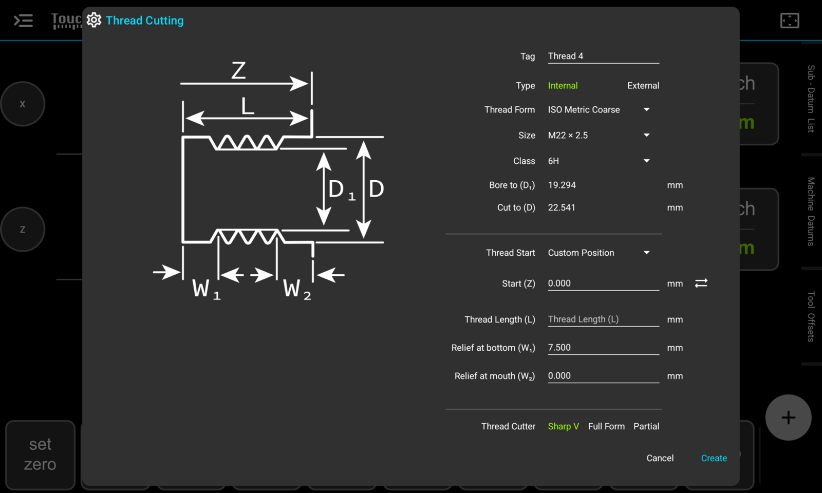
The left side of the dialog shows a cross-section of the thread with the dimensions labeled. The picture changes between a bore and a shaft when you change the thread type, and the letters on it match the letters next to the field names.
The dimension fields in this dialog use the units of the thread, regardless of the units the readout is set to. In other words, a metric thread is set up in millimeters and a Unified thread is set up in inches, the way they are shown on the print and in the charts. Once the thread is created, the readout and the thread cutting card show it in whichever units the readout is set to.
Tag
The tag is the name of the thread. TouchDRO fills it in as "Thread" followed by the next free number, and you can replace it with something more descriptive. TouchDRO assigns this tag to the guides and sub-datums that make up the thread, and it is the name you will see when there are several threads to choose from.
Type
"Internal" sets the thread up in a bore, and "External" sets it up on a shaft. The selection changes the picture, the available classes, and the names of the diameter and relief fields.
Thread Form, Size, and Class
The "Thread Form" list selects the thread series, and the "Size" list shows the standard sizes in that series by their usual designation, such as "M12 × 1.75" or "1/2-13":
| Thread Form | Sizes | Class (internal / external) |
|---|---|---|
| "ISO Metric Coarse" | M3 to M68 | 6H / 6g |
| "ISO Metric Fine" | M3 to M68, every standard fine pitch | 6H / 6g |
| "ANSI Coarse (UNC)" | #5-40 to 4-4 | 2B, 3B / 2A, 3A |
| "ANSI Fine (UNF)" | #5-44 to 1 1/2-12 | 2B, 3B / 2A, 3A |
| "ANSI Extra Fine (UNEF)" | #12-32 to 1 11/16-18 | 2B, 3B / 2A, 3A |
| "Custom Metric" | Pitch and diameters entered by hand | |
| "Custom Imperial" | TPI and diameters entered by hand | |
The lists start at 3 mm and #5. Threads smaller than that are not practical to single-point, and the standards don't tabulate a tolerance for the smallest of them.
The "Class" list sets the class of fit. TouchDRO uses the class to calculate the diameters, so a 3A thread will come out slightly larger than a 2A thread of the same size. If the standard doesn't list a tolerance for the selected size, the dialog will show a note that the diameters are the basic profile with no class allowance.
Diameters
For a standard thread, TouchDRO calculates the two diameters and shows them as read-only values. The field names tell you what each diameter is used for:
- For an internal thread, "Bore to (D1)" is the diameter to bore the hole to before threading, and "Cut to (D)" is the diameter the tip of the threading tool ends up at on the last pass.
- For an external thread, "Turn to (D)" is the diameter to turn the blank to before threading, and "Cut to (D1)" is the diameter the tip of the tool ends up at on the last pass.
Both values are diameters, regardless of the radius or diameter mode of the readout. The depth is calculated from the pitch diameter of the selected class, so a thread cut to the "Cut to" value with a correctly shaped tool will come out on size. The values depend on the "Thread Cutter" selection, so set that before you write the numbers down.
Thread Start and Start (Z)
"Start (Z)" is the Z position of the end of the part where the thread begins: the face of a shaft, or the mouth of a bore. The position is in the coordinates of the current workspace, so with the Z origin on the face of the part, it stays at 0. To take the position from the machine, bring the tool to the face and tap the sync button next to the field. This will copy the current Z reading into the field.
The "Thread Start" list has one option, "Custom Position", which means the position is the one entered in the "Start (Z)" field.
Thread Length
"Thread Length (L)" is the length of the whole threaded feature, measured from the start position toward the headstock. The length includes the relief grooves, so it has to be longer than the two reliefs together. The dialog will refuse a length of zero, or one that is too short, when you press "Create".
Relief Grooves
A single-point thread needs somewhere for the tool to stop. On most parts, this is a relief groove at the far end of the thread, cut before threading. The two relief fields tell TouchDRO how wide the grooves are, so it knows where the full thread ends and the groove begins:
- "Relief at shoulder (W1)", or "Relief at bottom (W1)" for an internal thread, is the groove at the headstock end, where the pass ends. TouchDRO fills it in as three times the pitch, which gives you room to disengage the half nuts. You can change the value to match the print.
- "Relief at face (W2)", or "Relief at mouth (W2)" for an internal thread, is a groove or a reduced section at the starting end. It starts out at 0, which means there is none.
The width is measured along the floor of the groove. Leave a field blank or set it to 0 for an end with no relief.
Thread Cutter
The "Thread Cutter" selection tells TouchDRO what kind of threading tool you are using, since the tool decides how the crest of the thread is formed and how deep the tip has to go:
- "Sharp V" is a tool with a sharp or nearly sharp point, such as a hand-ground high speed steel bit. The tool doesn't touch the crest, so the blank has to be turned or bored to the finished crest diameter. The tip goes to the full depth of the sharp V.
- "Full Form" is a full-profile insert made for one pitch. The insert cuts the crest along with the flanks, so the blank is left slightly oversize (or the bore slightly undersize) for it to clean up. The tip stops at the rounded root of the standard profile, which is shallower than the sharp V.
- "Partial" is a partial-profile insert that covers a range of pitches. TouchDRO doesn't know the nose radius of the insert, and at this time it calculates a partial-profile tool the same way as a sharp V. An insert with a noticeable nose radius will reach the correct pitch diameter a little before the "Cut to" value, so check the fit with a gauge or the mating part as you get close.
Custom Threads
"Custom Metric" and "Custom Imperial" are meant for a 60-degree thread that isn't in the lists, such as an oddball size on a repair job. The "Size" and "Class" rows are replaced with a "Pitch (P)" or "TPI" field, and the "Minor Diameter (D1)" and "Major Diameter (D)" fields become editable. TouchDRO uses the diameters exactly as you enter them, without any class allowance.
What Create Adds to the Workspace
When you press "Create", TouchDRO will check the entries. If something is missing or doesn't add up, the dialog stays open, a message at the top explains the problem, and the field in question turns red. Otherwise, TouchDRO will store the thread and add the following to the current workspace, all tagged with the thread's tag:
- Guides at the start and the end of the thread, and at the inner wall of each relief groove
- Guides at the major and the minor diameter, on both sides of the spindle centerline
- Sub-datums at the corners of the thread, on both sides of the centerline
These are ordinary guides and sub-datums. You can activate them, snap to them, and show or hide them by tag, as described in the "Working with Guides" and "Sub-Datum Tags and Filtering" guides. They are also useful before threading. For example, you can activate the diameter guide while boring the hole for an internal thread, and the relief guide while cutting the groove.
The corner sub-datums on the root diameter are the reason the thread is stored this way. When one of them is active, the X readout shows the distance to the root of the thread, and the Z readout shows the distance to the end of the thread. In other words, you cut the thread by working both axes to zero, the same way you would work to any other sub-datum. This is described in "Selecting the Finish Corner" below.
Step 2: Cutting the Thread
Once the thread is set up and the blank is ready, the rest of the work is done from the graphical view. Arming the thread tells TouchDRO which of the stored threads you are about to cut.
Arming the Thread
To arm the thread, open the graphical view and tap the "Arm thread cutting" button in the quick access row in the upper-left corner. What happens next depends on how many threads the workspace holds:
- With one thread in the workspace, TouchDRO will arm it right away.
- With several threads, the card will open with the "Select a Thread" list. Each row shows the tag followed by the designation, for example "Thread_2 · M22 × 2.5 internal". Tap the thread you are about to cut.
- With no threads, TouchDRO will offer to create one and will open the "Thread Cutting" dialog if you press "Create".
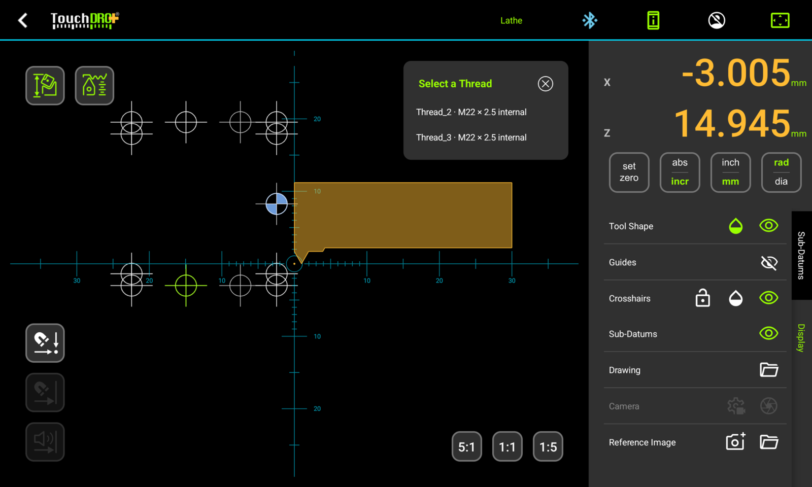
The button stays lit while a thread is armed. While it is, new sub-datums can't be added to the workspace, and the "Thread Cutting" setup dialog is not available.
Once the thread is armed, TouchDRO will draw its profile in the graphical view: the crests, the roots, the relief grooves, and a ramp at each end. The profile is drawn on both sides of the spindle centerline, as two separate halves. The red lines are the thread's guides, and the circles at the corners are its sub-datums.
When the applied tool has an outline attached, TouchDRO will draw the cutter against the profile to scale. This is a good moment to check that a boring bar fits inside the minor diameter and that the tool can reach the relief groove. The "Lathe Cutter Geometry" page explains how to add the outline.
Selecting the Finish Corner
The finish corner is the point where the last pass ends: on the root diameter of the thread, at the end where the tool stops. Selecting it makes it the active sub-datum, so both readouts switch to incremental mode and show the distance to that corner. X reads 0 when the tool is at the full depth of the thread. Z reads 0 at the end of the full thread, where the relief groove begins.
Since Z counts down to the end of the thread, you can use the "near-zero warning" as a cue to disengage the half nuts. To turn it on, open the "Axis Details" dialog for the Z axis and tap the near-zero warning button. TouchDRO will start beeping when the tool is within 0.100″ of the end of the thread. The beeps get faster as the tool gets closer and turn into a solid tone within 0.005″. The warning stays quiet on the return stroke, since the carriage is moving away from zero, and comes back on the next pass. This way, you can disengage the half nuts at the same spot on every pass by ear, without taking your eyes off the work. The relief groove is what gives you room to react after the beep, so it helps to make it as wide as the part allows.
TouchDRO selects a corner for you when the thread is armed. It picks the headstock end of the thread, on the operator's side of the centerline, which is the correct corner for a tool that cuts from the front toward the headstock. The half of the profile that holds the selected corner is highlighted.
To cut to a different corner, tap it in the graphical view. For example, tap the corner at the other end when threading away from the headstock, or a corner on the far half of the profile when the tool cuts on the back side of the part. If no corner is selected, the card will show "Select the finish corner" in place of the status.
The Thread Cutting Card
TouchDRO shows the card in the upper-right corner of the graphical view. Its title names the thread being cut, such as "Cutting M22 × 2.5 internal". Below the title are the status light and three rows of numbers. The numbers use the units and the radius or diameter mode of the X readout, so they can be compared directly with the big digits.
Status Light
The status light reports where the tip of the tool is in relation to the thread:
- Green, "Clear of the crests": the tool is at least 0.5 mm (0.020″) per side clear of the crests of the thread. The carriage can be moved back for the next pass.
- Amber, "In the cut": the tool is between the crests and the finished root.
- Red, "Past the root": the tool is deeper than the finished root of the thread.
This is especially useful in a bore, where you can't see the tool past the boring bar.
Last Pass
"Last pass" is the X reading of the deepest pass so far, in the same terms as the X readout. With the readout counting down to the finish corner, this is how much of the thread was left after that pass. The row shows a dash until the first pass has been registered.
Infeed
"Infeed" is the difference between the current X position and the last pass. After a retract, the number is negative while the tool is still backed out. It reaches zero when the tool is back at the depth of the last pass, and goes positive as you feed in for the next cut. In other words, "Infeed" is the depth of cut you are about to take. The number is colored to match the status light.
Cut Load
A V thread gets wider as it gets deeper. The same infeed that made a light cut on the second pass makes a heavy one near full depth, since the tool is cutting on a much longer length of its edges. This is the reason for the usual advice to reduce the depth of cut as the thread progresses.
The "Cut load ≈" row compares the cross-section of the chip you are about to take with the chip from the last pass that went deeper. For example, a reading of "1.0×" means the same amount of metal as last time. "1.5×" means half again as much, and "0.5×" means half. If the last pass cut well, keeping the reading near or below 1.0× keeps the load on the tool about the same. The row shows a dash when there is nothing to compare: before the first pass is registered, and while the tool is not set deeper than the last pass, which includes a spring pass.
Note that the number is only a comparison with the previous cut. TouchDRO doesn't know the material, the tool, or the rigidity of the machine, so it doesn't warn you when the number is high.
A Typical Threading Routine
The exact routine depends on your lathe and on how you like to thread. The steps below describe a typical external or internal thread cut toward the headstock, with the infeed on the cross slide.
- Set the thread up as described in "Step 1" above.
- Turn or bore the blank to the pre-op diameter from the "Thread Cutting" dialog, and cut the relief groove. The thread's diameter and relief guides can be used as targets for both.
- Mount the threading tool and apply its tool offset. Set the lathe up for the pitch.
- Open the graphical view, arm the thread, and check that the finish corner is the one where the pass will end. Turn on the near-zero warning for the Z axis.
- Take a light scratch pass and check the pitch. Once the carriage has traveled through the middle of the thread, "Last pass" will show the depth of the scratch.
- When the near-zero warning tells you that the tool is reaching the end of the thread, disengage the half nuts, and back the cross slide out until the light turns green. Return the carriage to the start.
- Feed the cross slide in until "Infeed" shows the depth of cut you want. Check "Cut load ≈" against the last pass, and take the pass.
- Repeat the last two steps, and watch the X readout count down. The thread is at the calculated depth when X reads 0.
- Take a spring pass or two at the same setting, and check the fit with a gauge or the mating part.
The calculated depth assumes a tool with the shape you selected in the "Thread Cutter" row. A real tool is rarely perfect, so start checking the fit a little before X reaches 0. If the thread needs to go deeper, you can keep cutting past zero. The light will turn red past the calculated root, and the card will keep tracking the passes.
Feeding with the Compound Slide
Many machinists set the compound over to 29 or 30 degrees and feed with it, so the tool cuts mostly on one flank. TouchDRO measures the depth of the thread from the X axis scale. On most lathes the compound slide has no scale, so feeding with it doesn't change the X reading, and the card will show no infeed.
There are two ways to deal with this. The first is to feed with the cross slide, which is how the thread cutting card is designed to be used. Carbide threading inserts are commonly run with a straight infeed, especially on finer pitches. The second is to put a scale on the compound slide and turn on "Compound Slide Angle Compensation", which adds the compound's travel to the X and Z readouts.
Closing the Card and Coming Back
To close the card, tap the close button in its corner, or tap the "Arm thread cutting" button again. The thread's guides and sub-datums stay in the workspace.
TouchDRO remembers the armed thread, the selected corner, and the deepest pass. If the tablet restarts or you leave the graphical view in the middle of the job, TouchDRO will restore the card the way you left it. Arming the same thread again later keeps its last pass, so a job can be picked up where it stopped, provided the part and the tool have not moved in relation to the workspace. Arming a different thread clears the last pass.
Changing or Deleting a Thread
A thread can't be edited after it is created. The positions of its sub-datums are locked, although you can still rename and retag them. To change a thread, delete it and create a new one. The dialog opens with the settings of the last thread you created, so setting it up again takes a few taps.
To delete a thread, delete its sub-datums. The quickest way is to filter the sub-datum list by the thread's tag and delete the whole group. When the last of them goes, TouchDRO will delete the stored thread as well, and the confirmation dialog will say so. Deleting a workspace deletes the threads in it the same way.
While a thread is being cut, new sub-datums can't be added to the workspace, so the "Thread Cutting" button is dimmed and will bring up the "Not Available Right Now" message. Close the thread cutting card first.