
Mill Head Tilt/Nod Compensation
When the head of a milling machine is vertical, quill travel and knee travel measure the same direction. The DRO can simply add the two scales together to get the Z position. Once the head is tilted, that stops being true. Part of every quill movement now lands along X or Y, and the vertical portion shrinks. A readout that keeps adding raw quill travel to the knee will drift away from the true cutter position.
The "Head Angle Compensation" function corrects for this. Given the head's two lean angles, TouchDRO splits quill travel into its true components and adds each component to the matching axis readout.
This is the milling half of a feature pair. On a lathe profile the "Compound Slide Angle Compensation" function does the same job, projecting compound slide travel onto the X and Z axes.
What TouchDRO Does
You tell TouchDRO how far the head is leaning. It works out how much of each quill movement went sideways and how much went straight down. The sideways part is added to the X and Y readouts, and what is left goes to Z. All three readouts then follow the cutter itself instead of following the quill.
The head can lean two ways, and TouchDRO handles them separately. A head leaning both ways at once is fine.
Z is always corrected, and there is no switch to turn that off. Once the head leans, less of each quill movement goes straight down. Z has to account for that whether or not you want the sideways corrections. With both angles set to zero nothing is corrected at all, and Z shows plain knee-plus-quill travel.
Availability
Beyond that, the function's button appears in the function strip only when all of the following are true:
- A quill scale is configured and enabled as the Z axis's secondary input
- That same input is not also assigned to the X or Y axis
- That same input is not also the Z axis's own primary input
If any of these fails, the button is hidden entirely rather than grayed out. The reason is worth understanding. If the quill's input also fed X, arming the function would make X count the same scale twice: once as its own input and once more through the projection. The axis would still read, still zero, and still probe; it would just be wrong by an amount that depends on the angle. Hiding the function turns an input assignment mistake into "the function is unavailable" instead of a readout that lies.
User Interface Overview
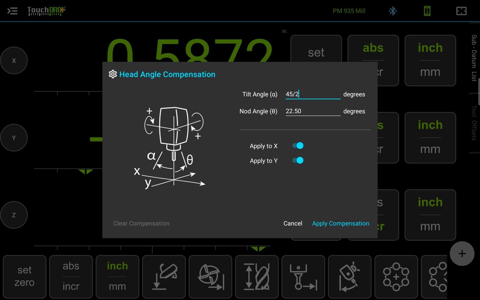
Tilt Angle (α) and Nod Angle (θ)
Stand in front of the machine and look straight at it. Tilt is the head leaning left or right, and nod is the head leaning toward you or away from you. The "Tilt Angle (α)" field holds the first of those, and the "Nod Angle (θ)" field holds the second. Each field accepts any value between -90 and +90 degrees.
The drawing in the dialog defines the sign convention: it shows both angles measured from the spindle axis, with the positive direction of each rotation marked. Measure your head's lean against the drawing rather than against the protractor markings on the machine, since those conventions vary from one machine to the next.
Both fields accept simple arithmetic as well as plain numbers; entering "45/2", for instance, produces 22.50 degrees. Trigonometric functions are not available, so an expression like "sin(30)" will not evaluate.
Apply to X and Apply to Y
The "Apply to X" and "Apply to Y" toggles control whether the corresponding horizontal component is added to that axis's readout. Both are switched on by default. There is no toggle for Z, for the reason covered above: the Z component is not a contribution you can decline.
Dialog Buttons
The "Apply Compensation" button arms the function with the entered angles, and the "Cancel" button closes the dialog without changing anything.
The "Clear Compensation" button switches the function off and stays disabled until the function is armed. It gets a dedicated button because clearing is a frequent, first-class action in normal work, not the undo of a mistake.
Applying Compensation
Enter the two angles, check the toggles, and press "Apply Compensation". The dialog will first validate the pair of angles together. Each angle is legal on its own anywhere within its -90 to +90 range. The two leans compete for the same vertical travel, though, and past a point there is none left. A combination that no physical head can hold is rejected with the message "A head cannot lean this far toward X and Y at once. Reduce the nod angle, the tilt angle, or both."
When the angles pass the check, the compensation takes effect the instant the button is pressed. The readouts repaint immediately rather than waiting for the next scale reading.
What Amber and Green Mean
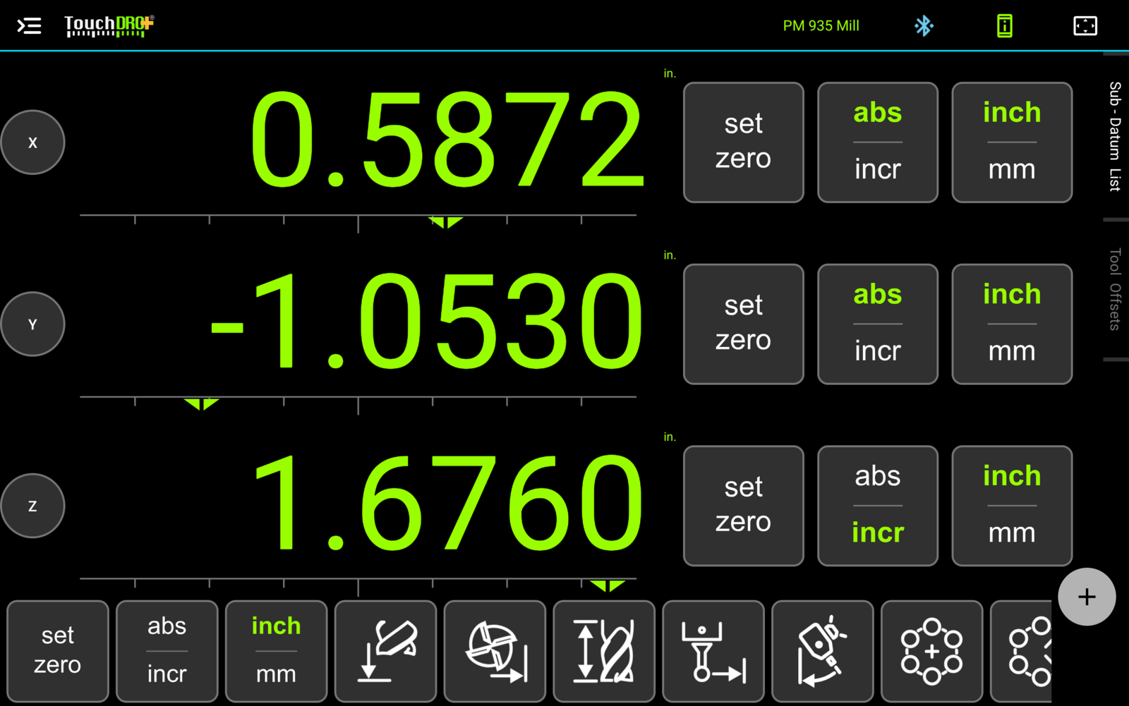
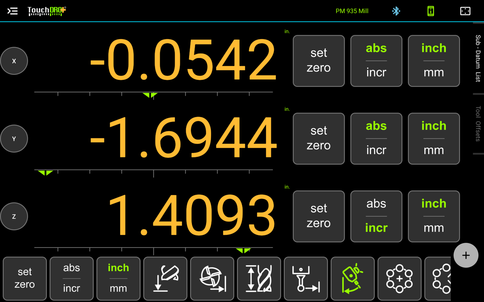
After applying, two separate indicators light up, and they answer two different questions. The function's icon lit green means the function is armed. A readout shown amber means that axis's displayed position is actually being shifted by the projection.
These are deliberately not the same thing. An armed function with the "Apply to Y" toggle switched off leaves Y reading its raw position, so Y stays green while X and Z turn amber. Similarly, an armed function with both angles at zero shifts nothing, and every readout stays green even though the icon is lit. Amber never merely echoes a switch; it lights only when the number on the screen is being adjusted, which is what makes it worth trusting.
In Fig. 3 all three readouts are amber even though only X and Y have toggles. This is the Z behavior described earlier. Z always takes the remaining component of quill travel. Once the head leans at all, its readout is being adjusted along with the rest.
Clearing Compensation
To switch the function off, reopen the dialog and press "Clear Compensation". TouchDRO will ask for confirmation ("Are you sure you want to clear the head tilt compensation?") and then return every readout to its raw reading.