
Rotate Part Function for Rotary Tables
When you machine a part mounted to a rotary table, the moment you index the table the coordinates on your DRO stop matching the print. The features are still where the drawing says they are on the part, but the part has turned under the spindle, so reaching the next one means working out its radius and included angle and converting back to X and Y at the new table position, feature by feature.
The "Rotate Part" function handles that for you. It turns the stored geometry with the table, so you keep driving to the numbers the print gives. TouchDRO can read the table angle live from an encoder on the rotary axis, so the geometry follows the table as you index, or take a typed angle when the part is fixed at a known one: a casting sitting at an angle to the vise jaws, a job on an angle plate, or a second operation whose datum edge runs off square to the first.
The Rotate Part Dialog
To open the dialog, tap the "Rotate Part" button in the function strip. The illustration on the left of the dialog shows which way the angle runs: zero points along the reference direction, and a positive angle α turns the part clockwise from there.
Angle Source
"Encoder" reads the angle live from the machine's angular axis, which is the setting for a rotary table. TouchDRO holds the geometry at whatever angle the axis reports, so you can index to any position and drive to the next feature by taking X and Y to zero.
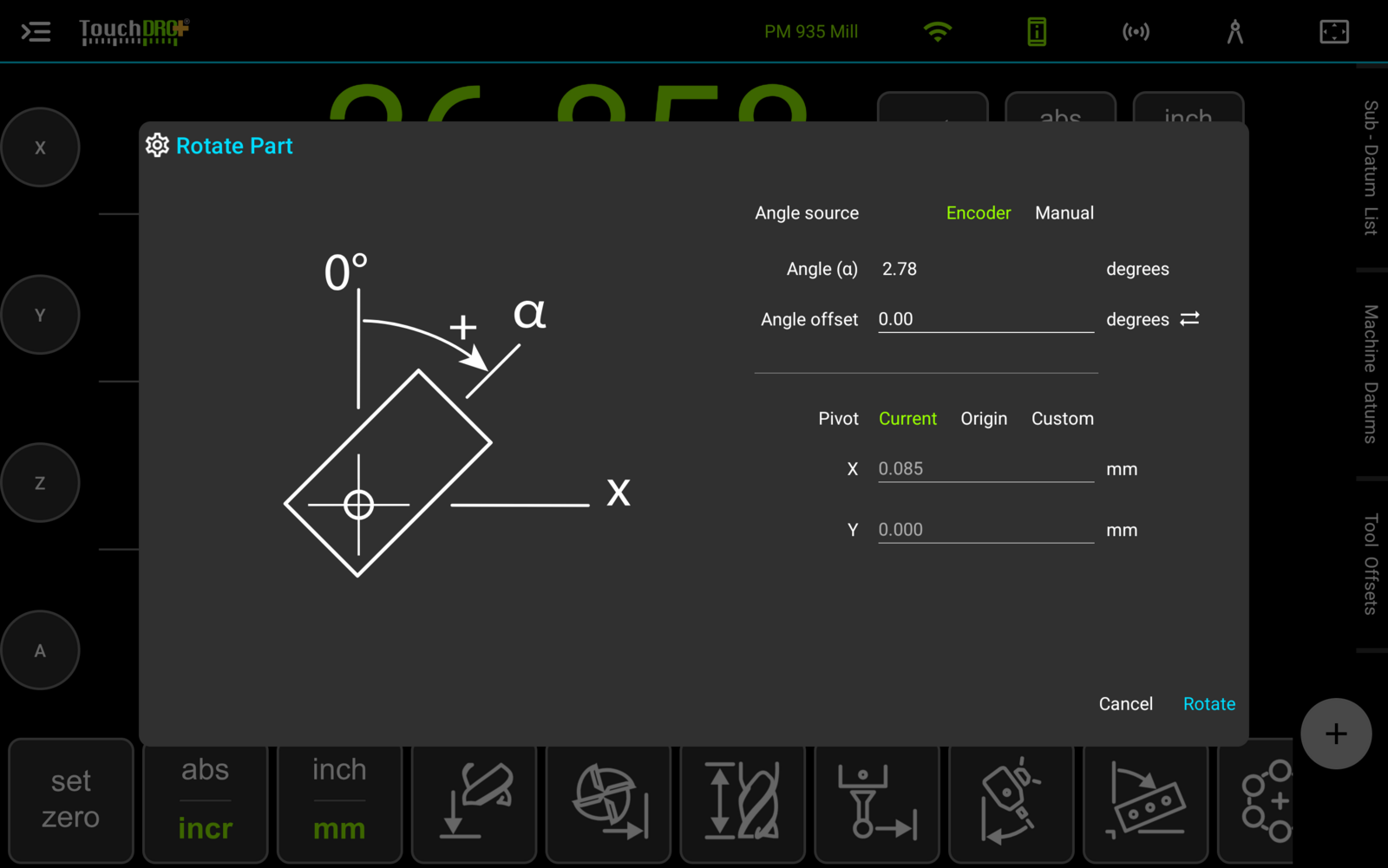
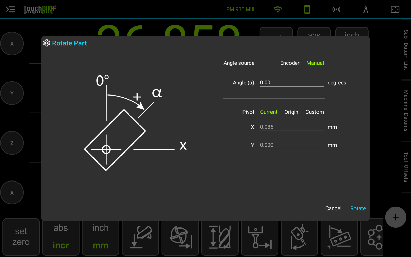
"Manual" takes a typed angle instead, for a part that is fixed at a known angle rather than turning under you. The two sources are alternatives: selecting one deselects the other.
Angle Offset
The angle the encoder reports is rarely zero at the orientation your drawing describes, and the table's own handwheel may be nowhere near a round number when the part is where you want it. "Angle offset" absorbs that difference.
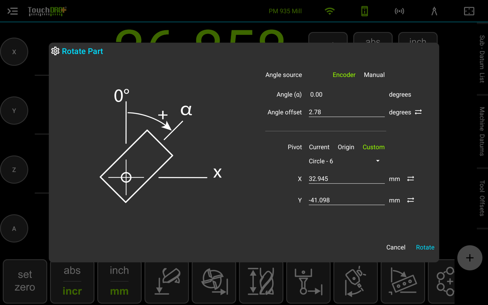
Set the part to the orientation the drawing describes, then tap the sync button beside "Angle offset". TouchDRO takes the angle the axis is reporting and files it as the offset, so "Angle (α)" reads 0.00 with the part at its reference position, and the geometry sits unturned. From there the angle counts from the part rather than from wherever the table happened to be.
Pivot
The pivot is the point the geometry turns about, and on a rotary table it is the center of the table. There are three ways to set it:
- "Current" uses the spindle's position, for when you have just centered over the table
- "Origin" uses the workspace origin
- "Custom" opens a sub-datum picker, so a center you found earlier and saved can serve as the pivot
With "Custom" selected you can also type the coordinates, or capture the current position into either field with its sync button. The pivot coordinates are readout numbers, and a part rotation leaves the rows reading machine position, so a figure you type straight off the readouts is already in the frame TouchDRO expects.
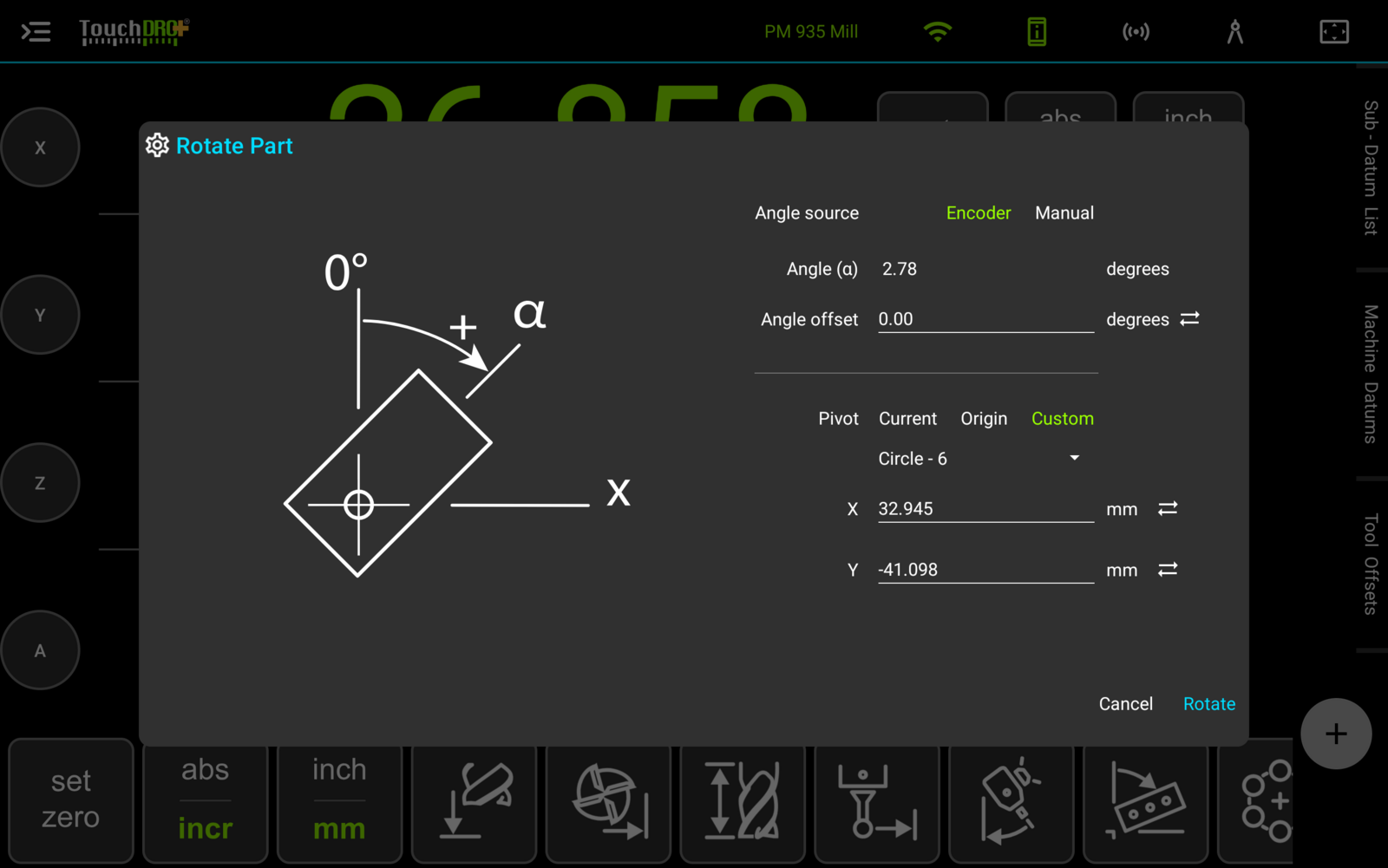
Tap "Rotate" to apply, and the geometry takes up the angle.
What Moves and What Stays
The part moves and the machine stays put. Sub-datums, the imported drawing and the reference image all turn about the pivot together on the graphical view, while the grid, the rulers and the crosshairs hold still, so the screen keeps showing the machine's own axes underneath the turned part.
The readouts report machine position throughout. X and Y count where the table is, in the machine's coordinates, which is what lets you drive to a turned feature by working the handwheels to zero as usual. They keep their normal color for the same reason: amber is reserved for a readout that reports something other than machine position, which is what "Align Measurement Axes" does.
The sub-datum list keeps showing each point's stored coordinates, the ones you typed or imported. Those are the drawing's numbers and they stay put while the angle changes.
On the Graphical View
While a rotation is in force, TouchDRO reports the angle at the top center of the canvas, marked with a turning arrow, and draws a protractor ring centered on the pivot. The ring's ticks point inwards, zero sits at twelve o'clock, and a positive angle runs clockwise from it, matching the illustration in the dialog.
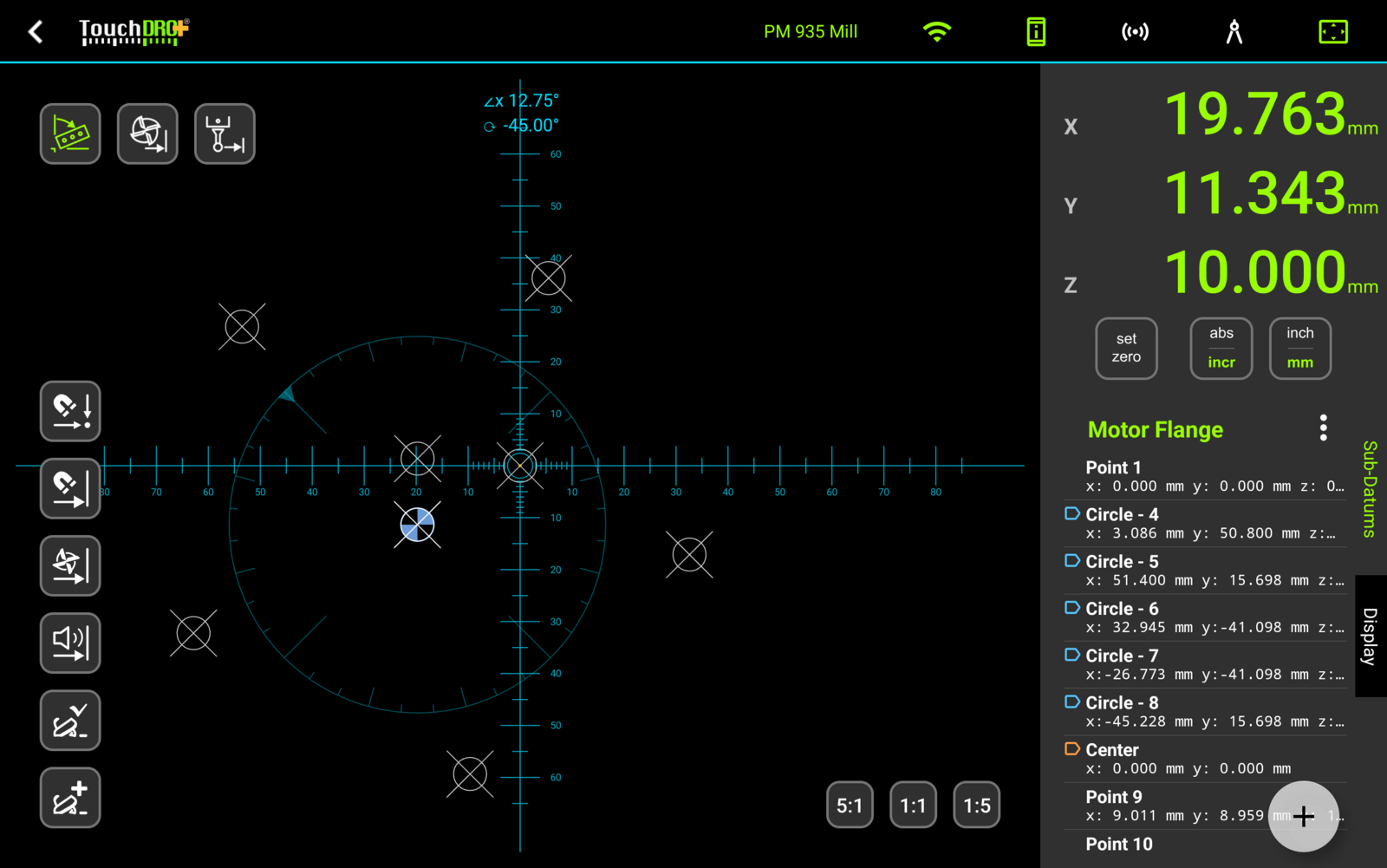
The two rotations can be in force together, and each keeps its own label and its own ring. The "Align Measurement Axes" ring points its ticks outwards and stays centered, so the pair read apart at a glance.
Clearing the Rotation
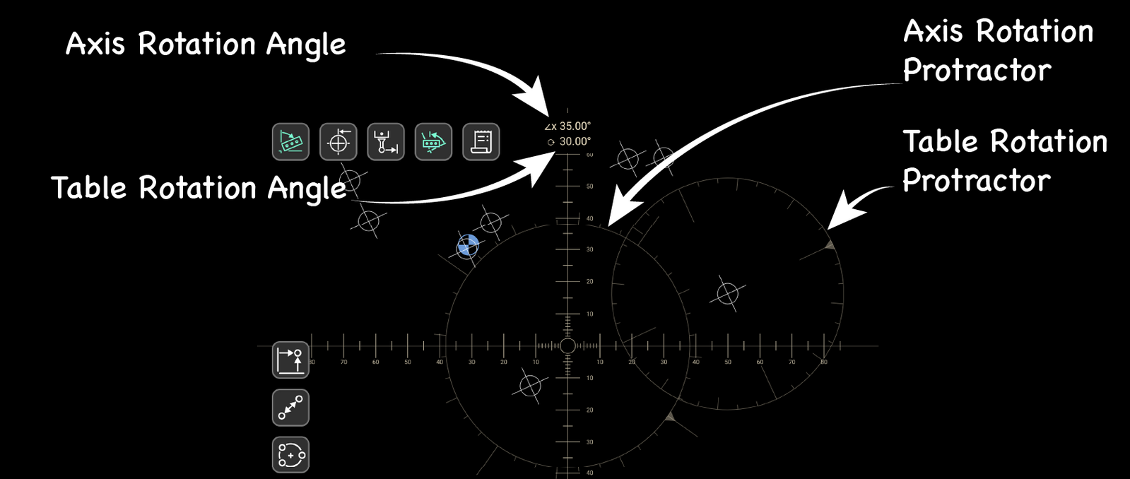
To take the rotation off, open the dialog and tap "Clear". A long-press on the button does the same, after a confirmation. The geometry returns to the angle it was drawn at, the label and the ring come off the canvas, and the stored coordinates are untouched throughout.
Working on a Rotary Table
Set the part up as you normally would, with the rotary table centered under the spindle and the part indicated to the table.
The pivot is the table's center, so it is worth finding once and keeping. The "Indicate Workpiece" function will pick up the center of the table's center bore in one operation. If you save that position as a sub-datum, the "Custom" pivot picker can recall it for the rest of the job.
Laying Out the Job from the Print
Lay out the job in a workspace the same way you would for a part clamped flat: type the coordinates in, import them from a spreadsheet, or generate them with the "Hole Circle" and "Hole Grid" functions. Every coordinate is measured from the part's own zero, which is what the drawing does, so the layout is worth doing at the desk before the part is even clamped.
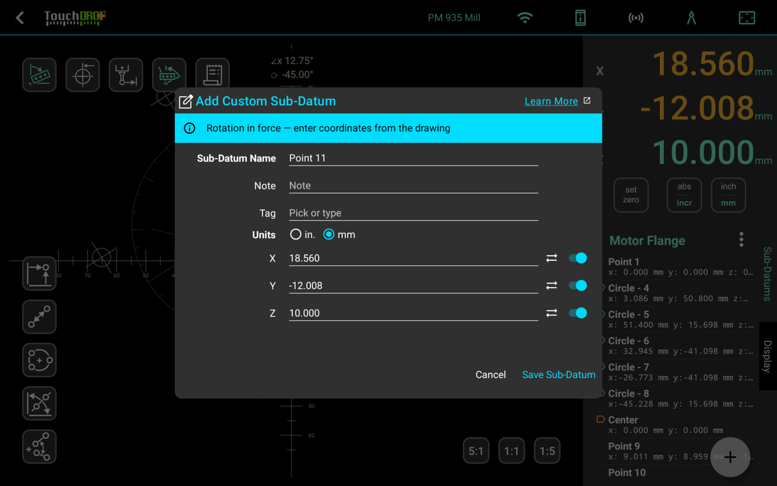
You can add points mid-job as well. To type one in, tap the add button at the bottom of the sub-datum panel and choose "Custom Coordinate", or double-tap an empty row in the list. Either opens the "Add Custom Sub-Datum" dialog. While a rotation is in force, the dialog says so across the top: enter the X and Y the drawing calls for, and TouchDRO does not apply the angle to them.
Indexing by Hand
On a plain rotary table, the table's own degree wheel is the angle, and you tell TouchDRO what it reads.
- Set the pivot to the table's center: center the spindle over it and choose "Current", or choose "Custom" and pick the point you saved for it
- Index the table to the first position and drill the features the drawing puts there
- Index to the next position, open the dialog, choose "Manual", and type the angle you turned to
- Tap "Rotate". The geometry takes up the new angle, and the coordinates on the print are live again
Following an Encoder
With an encoder on the rotary axis, the table reports its own angle and you set the function up once.
- Set the pivot to the table's center, the same way
- Turn the table to the orientation the drawing describes, then tap the sync button beside "Angle offset" so "Angle (α)" reads 0.00 there
- Choose "Encoder" and tap "Rotate"
- Index to any position you like. The geometry follows the table, and every feature is where the print says it is
From here the job runs the way it would on a part clamped flat: activate the sub-datum you want and drive X and Y to zero.
Accuracy
On an encoder-equipped rotary table, TouchDRO takes the angle from the encoder on the rotary axis, and the encoder's resolution sets how finely the geometry can follow the table. Where that encoder sits matters more than the encoder itself: mounted on the handwheel it turns once per worm revolution, so the table's own reduction multiplies its resolution by the gear ratio.
A 500 PPR encoder reads 2,000 counts per revolution in quadrature. On the handwheel of a 72:1 table that works out to 144,000 counts for one turn of the table, which is finer than anything else on the machine.
Angular error turns into position error in proportion to how far the feature sits from the pivot, so the same encoder buys more on a small part than a large one. The last column is what each resolution comes to at a 100 mm working radius.
| Encoder and mounting | Counts per table revolution | Resolution | At 100 mm radius |
|---|---|---|---|
| 500 PPR on the handwheel, 72:1 table | 144,000 | 0.0025° | 0.004 mm |
| 100 PPR on the handwheel, 72:1 table | 28,800 | 0.0125° | 0.022 mm |
| 1,000 PPR direct on the table spindle | 4,000 | 0.09° | 0.157 mm |
The gap between the first and last rows is the worm doing the work. A modest encoder geared through the table beats a much better one reading the spindle, which is why a handwheel mount is worth the awkwardness on a dividing head or a rotary table that offers both.
TouchDRO shows the angle as it reads it, without smoothing or a deadband, so a jittery reading on screen is the encoder telling you something worth knowing.