Hole Grid Function
Rows and grids of holes are everywhere: mounting plates, tooling plates, connector cutouts, louver patterns. The hole grid function takes a spacing and a count for each direction and saves every hole position into sub-datum memory. Laying out a 20-hole plate costs four entries instead of twenty pairs of coordinates.
For a row dimensioned by its two end holes rather than its spacing, the "Equidistant Hole Array" function is the more direct route.
A grid can be one-dimensional (a single row of holes, straight or at an angle) or two-dimensional. This function is primarily intended for a milling machine; on a lathe it projects on the X/Z plane, where it can be used to rough out conical shapes.
Opening the Dialog
To open the "Hole Grid" dialog, press the "Hole Grid" button in the function strip, or select "Hole Grid" from the "Add Sub-Datum" menu in the sub-datum panel.
Grid Parameters
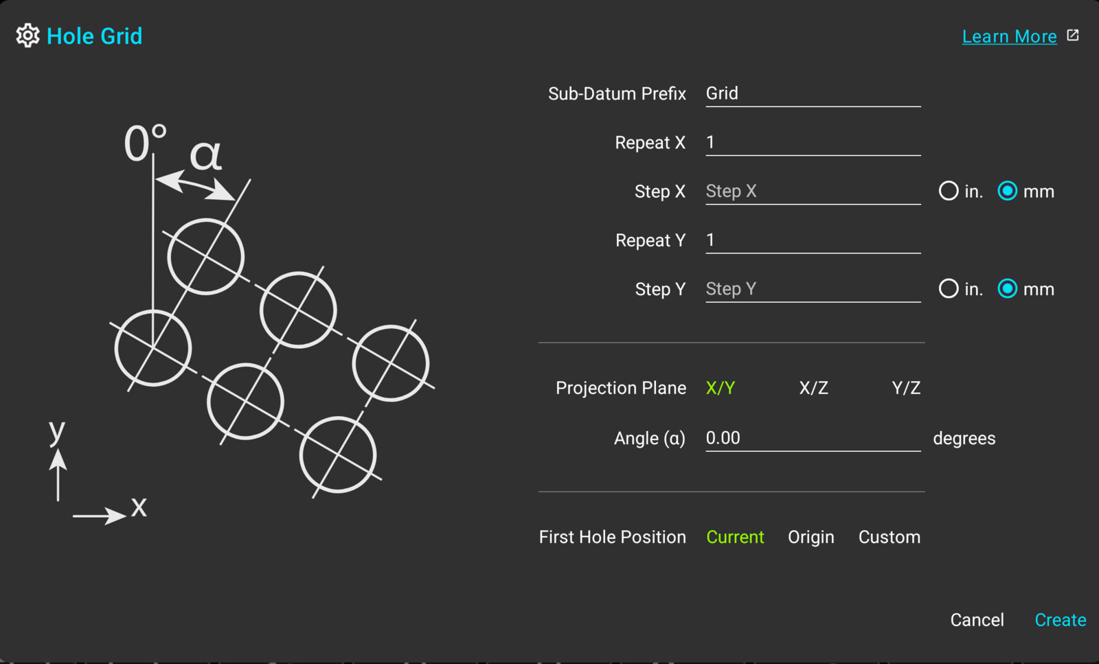
Sub-Datum Prefix
The prefix names the created holes ("Grid - 1", "Grid - 2", and so on) and becomes a tag on every one of them, so the whole grid can be filtered, hidden, or deleted as a group later.
Repeat and Step
Each direction of the grid takes two figures: "Repeat" is the number of holes along that direction, and "Step" is the distance between them. At least one of the two "Repeat" values has to be larger than 1. A direction that repeats needs its step; the other direction can be left alone for a single row.
Each "Step" field carries its own "in."/"mm" selection, so a metric spacing can be entered on a readout showing inches. The fields accept arithmetic, so a spacing given on a drawing as 3/16" is typed exactly that way.
Projection Plane and Angle
The "Projection Plane" selection works as it does in the "Hole Circle" function, defaulting to X/Y on a mill. The angle α rotates the whole grid around its first hole. At 0 the rows run parallel to the axes; a positive angle swings the grid clockwise, as the drawing in the dialog shows.
Positioning the Grid
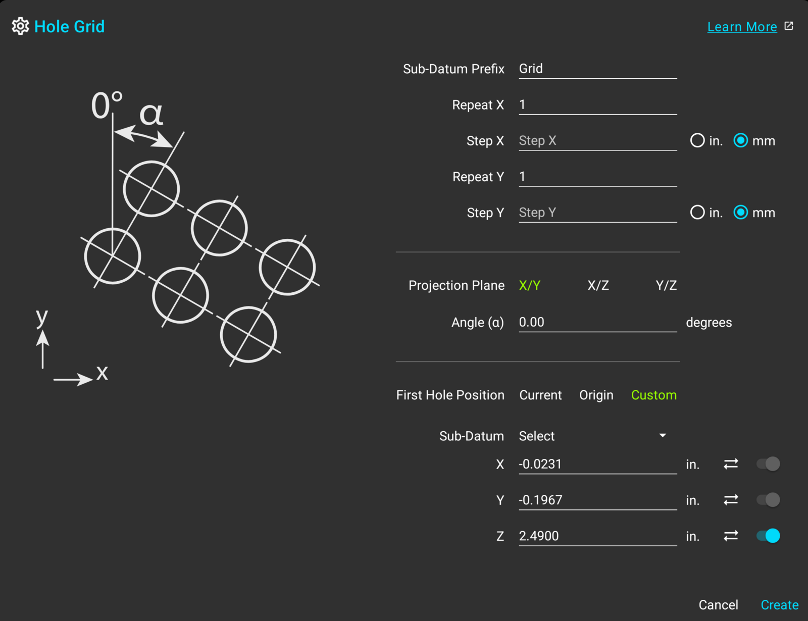
The grid is anchored by its first hole, and the "First Hole Position" selection places it. "Current" uses the machine's position, and "Origin" uses the workspace's absolute zero. "Custom" opens the shared set of coordinate fields, with a stored sub-datum dropdown, per-axis "Sync" buttons, and an optional third axis; those controls are covered in "Hole Circle".
The Created Holes
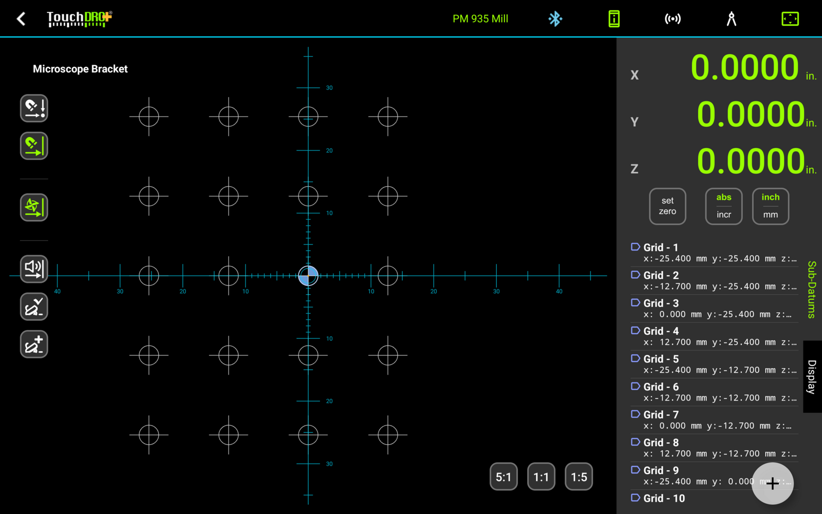
When you press "Create", TouchDRO checks the entries and writes the holes into the current workspace as ordinary sub-datums: they appear in the sub-datum list named by the prefix, and are drawn at their positions in the Graphical View display, where tapping a hole activates it and the readouts count down to it.
The prefix also becomes a tag on every hole, and the tag filter can show or hide the whole grid in one tap, in the list and in the view alike. On a plate that carries more than one pattern, filtering down to one tag keeps the list workable.
How To Use
Rectangular Hole Grid
Goal: drill a 4 × 5 grid of holes with 0.5" spacing in both directions, starting at the current spindle position.
- Move the spindle to the first hole position
- Bring up the "Hole Grid" dialog
- Enter 4 into the "Repeat X" field
- Enter .5 into the "Step X" field and select "in."
- Enter 5 into the "Repeat Y" field
- Enter .5 into the "Step Y" field and select "in."
- Leave "First Hole Position" on "Current"
- Press "Create"
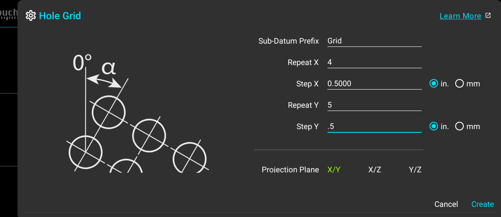
The 20 holes arrive in the sub-datum list named "Grid - 1" through "Grid - 20" and tagged "Grid", with the first hole at the position the spindle was sitting on: