Hole Circle Function
Laying out a bolt hole circle by hand means working out a sine and cosine for every hole and dialing each pair in without a mistake. The hole circle function does that arithmetic for you: enter the radius, the number of holes, and where the circle sits, and TouchDRO will calculate every hole position and save it into sub-datum memory. Machinists also know this layout as a Pitch Circle Diameter (PCD) pattern.
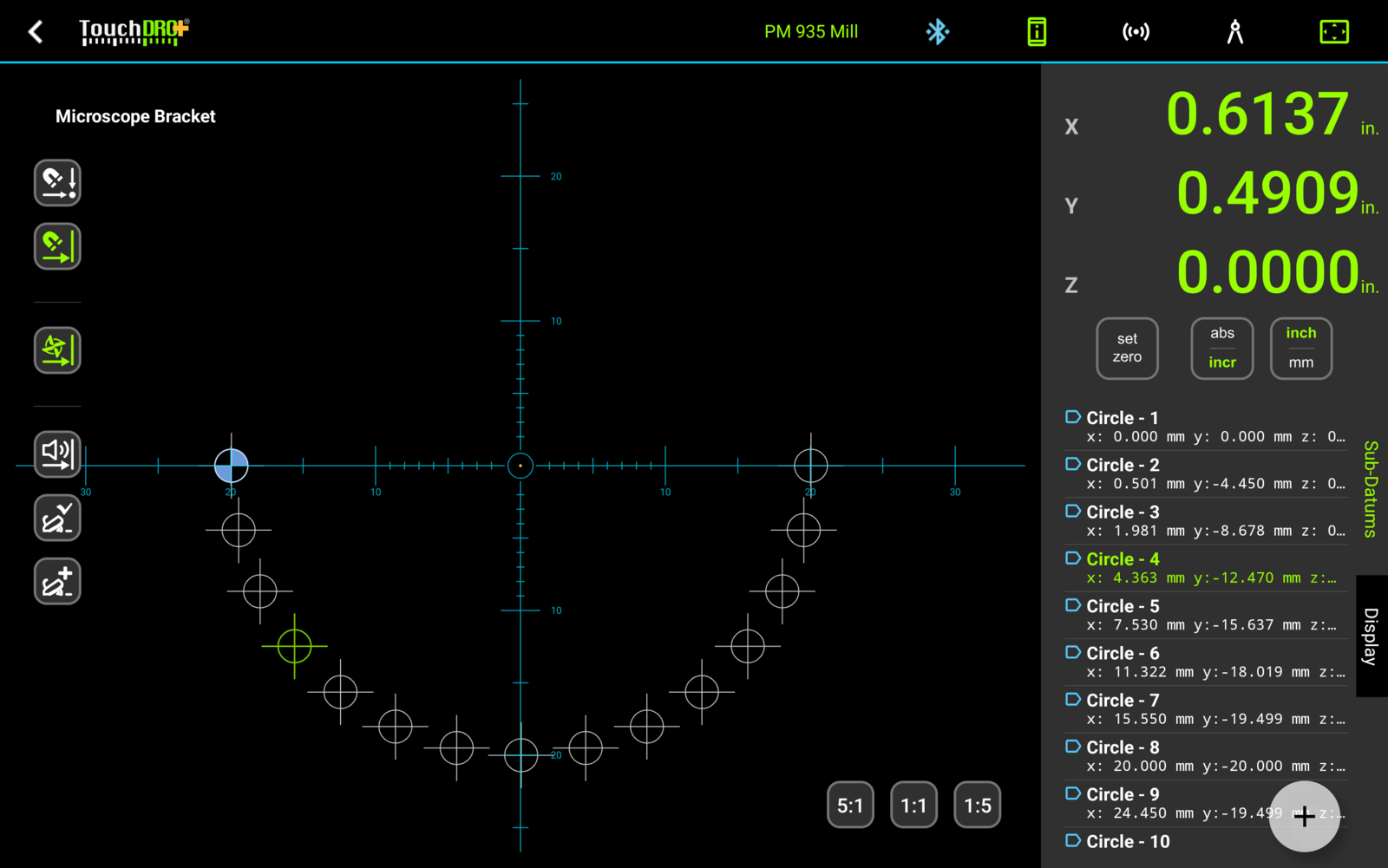
Once the holes are in sub-datum memory, you work the pattern the way you work any other saved coordinates: tap a hole in the list, crank the axes to zero, and drill. The Graphical View display shows the whole circle to scale, so a skipped or doubled hole is visible before the drill touches metal.
Opening the Dialog
To open the "Hole Circle" dialog, press the "Hole Circle" button in the function strip, or select "Hole Circle" from the "Add Sub-Datum" menu in the sub-datum panel.
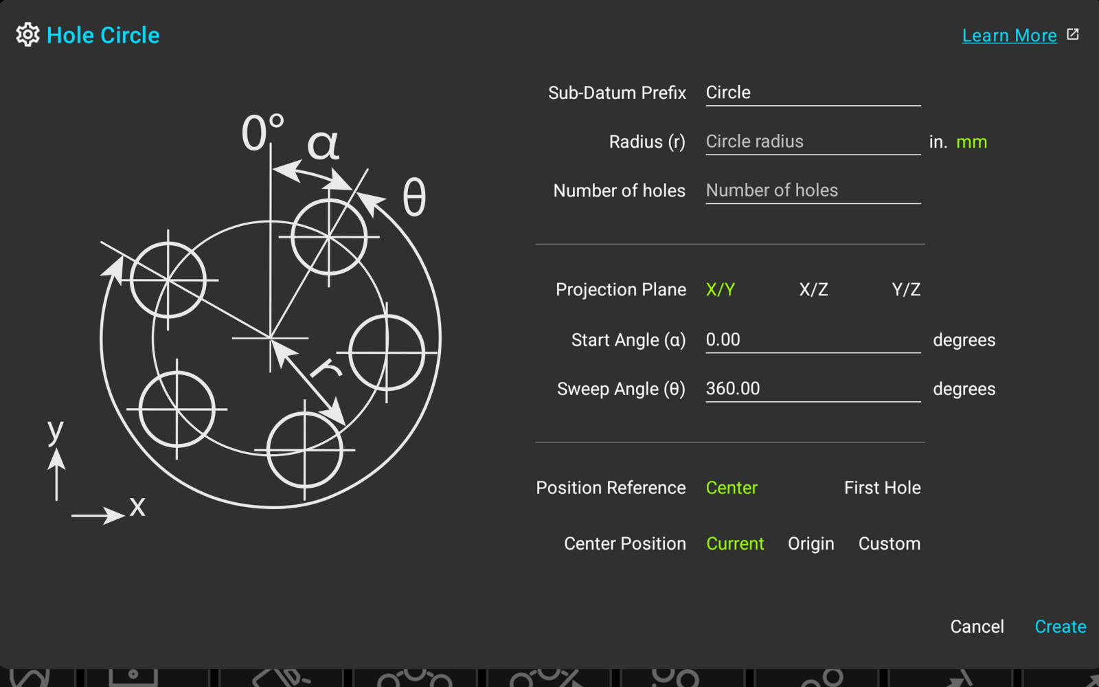
The drawing on the left shows what each figure describes: the radius r, the start angle α measured from the 0° mark, and the sweep angle θ.
Circle Parameters
Sub-Datum Prefix
The prefix is the name the created holes will carry, followed by a running number, so the default "Circle" produces "Circle - 1", "Circle - 2", and so on. The same prefix becomes a tag on every hole, which is what makes the whole pattern easy to filter, hide, or delete as one group later.
Radius
The circle radius is required and has to be a positive number. The field accepts arithmetic, so a 3¾" bolt circle diameter can be entered as "3+3/4/2" without reaching for a calculator.
The "in." and "mm" selection next to the field belongs to this entry alone, so a metric radius can be entered on a readout showing inches. By default it follows the "Metric Mode" application setting.
Number of Holes
The number of holes is required and can be anything from 2 to 100.
Projection Plane
The "Projection Plane" selection sets the plane the circle is calculated on. X/Y is the default on a mill, and the two other choices exist for the less common setups: X/Z for a pattern worked with a horizontal spindle, Y/Z for one worked off the side of the part. On a lathe the plane is fixed at X/Z, and the selection is not shown.
Start and Sweep Angles
The start angle α places the first hole, and the sweep angle θ sets how much of the circle the pattern covers. Both accept values from -360 to 360 degrees; α defaults to 0 and θ defaults to 360. The 0° mark points along the vertical axis of the drawing (positive Y on the X/Y plane), and positive angles run clockwise.
TouchDRO handles the sweep differently from most traditional DROs:
- At θ = 360° (a full circle), TouchDRO divides the circle into the requested number of holes, and the last hole does not land on top of the first
- At any smaller sweep, the first and last holes land exactly on the start and end angles, with the remaining holes spaced equally between them
In other words, a full circle of 6 holes is entered as 6 holes, not 7. This is more intuitive than the traditional convention, but it's worth remembering when transferring a pattern from an old DRO's manual.
Positioning the Circle
Position Reference
The "Position Reference" selection decides which point of the pattern the position below refers to:
- "Center" - the position is the center of the circle
- "First Hole" - the position is the first hole itself, and TouchDRO calculates where the center falls. This is the choice when a hole location is known or already spotted, but the center is empty air or off the part
Current, Origin, and Custom
The position itself comes from one of three places:
- "Current" - the current position of the machine. Move the spindle to the center (or the first hole), leave the selection alone, and the pattern lands where the machine sits
- "Origin" - the workspace's absolute zero
- "Custom" - typed-in coordinates. Selecting it opens a set of position fields, pre-filled with the current readings
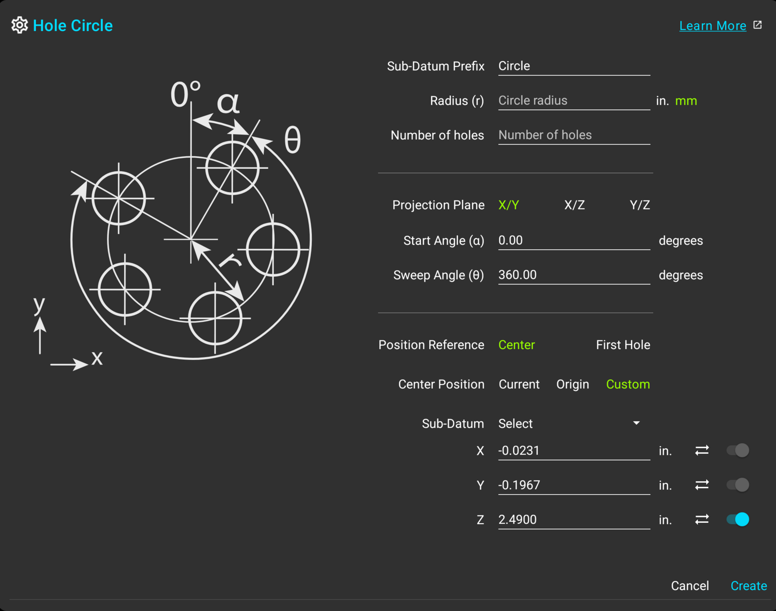
The custom fields work the same way in every generator dialog:
- The "Sub-Datum" dropdown loads the coordinates of a stored sub-datum into the fields, so a pattern can be placed on a point you saved earlier without retyping it
- The two axes of the projection plane are required; each field accepts arithmetic in the units its axis is currently displaying
- The "Sync" button next to a field restores the current reading for that axis
- The switch at the end of the third axis row decides whether the holes carry that coordinate. Switched on, every hole is stored with the entered value (a drilling depth, for instance); switched off, the holes are created with no third-axis value at all
The Created Holes
When you press "Create", TouchDRO checks the entries, and either marks the fields that need attention or writes the holes into the current workspace. The holes arrive as ordinary sub-datums: they show up in the sub-datum list named by the prefix, tagged with the prefix, and drawn in the Graphical View display at their positions.
From here on, nothing about them is special. They can be renamed, re-tagged, deleted one at a time or by tag, and worked through with the navigation buttons like any other saved coordinates. The workflow is covered in "The Sub-Datum Panel".
The tag earns its keep on a crowded workspace. The tag filter can show or hide the whole pattern in one tap, both in the list and in the Graphical View display, so you can work one pattern at a time with everything else out of the way.
How To Use
Full Hole Circle
Goal: drill a 12-hole circle with a 1⅞" radius, centered at the current spindle position.
- Move the spindle to the center of the pattern
- Bring up the "Hole Circle" dialog
- Enter "1+7/8" into the "Radius" field
- Select "in." next to the field
- Enter 12 into the "Number of holes" field
- Leave "Position Reference" on "Center" and "Center Position" on "Current"
- Press "Create"
Partial Circle From the First Hole
Goal: a 15-hole concave half-circle with a 20 mm radius, with the first hole at the current position and the arc opening downward.
- Move the spindle to the first hole position
- Bring up the "Hole Circle" dialog
- Enter 20 into the "Radius" field and select "mm"
- Enter 15 into the "Number of holes" field
- Enter -90 into the "Start Angle" field
- Enter -180 into the "Sweep Angle" field
- Set "Position Reference" to "First Hole" and leave "First Hole Position" on "Current"
- Press "Create"
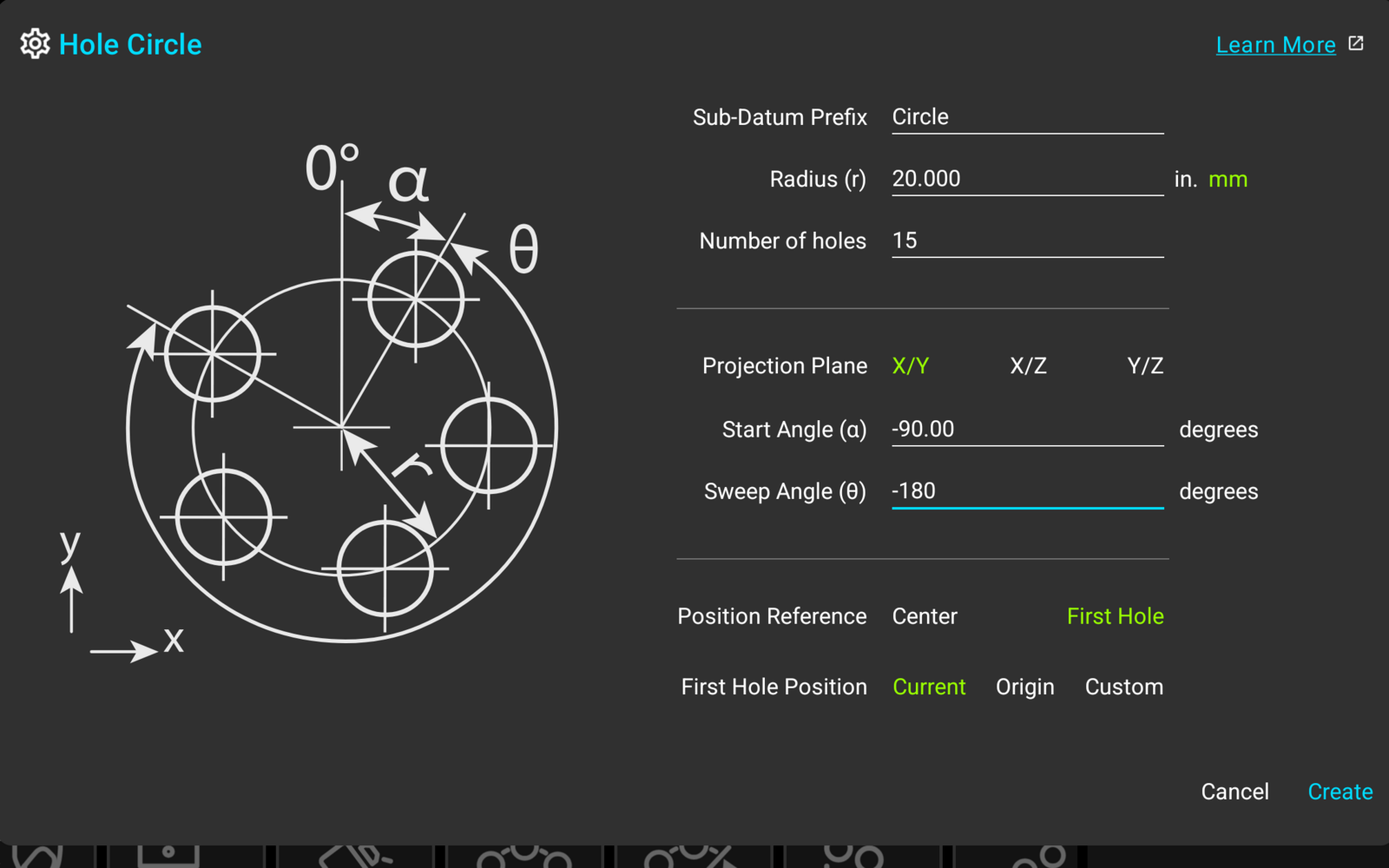
The -90 start angle puts the first hole at the 9 o'clock position, and the -180 sweep runs the pattern counterclockwise from there, which is what makes the arc concave. A sweep of 180 would produce the convex mirror image.