
Improving Magnetic DRO Scale Accuracy
Every DRO scale, regardless of its price point, carries some amount of error that depends on the manufacturing tolerances and the scale's architecture. For the most part, even on budget scales the error is small enough that it doesn't matter in a machine shop. The notable exception is magnetic DRO scales: regardless of the brand or price, their inherent non-linear error can easily be an order of magnitude larger than that of similarly priced optical (glass) scales.
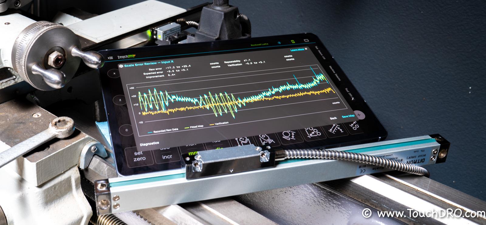
This doesn't make magnetic scales bad, but it does mean that to produce accurate readings they need to be calibrated. In shops that do certified work, this is a solved problem: every year or so a technician comes by with a laser interferometer, produces a fresh error map, uploads it into the DRO console, and leaves a four-figure bill on the way out. Most small machine shops and hobbyist garages don't have access to a portable interferometer (which can cost more than a family SUV), so this guide covers the practical alternative.
On this page, I will cover how to check the accuracy of your digital readout scales using tools you likely already own, and how to use TouchDRO's Error Map Wizard to measure and correct the error using a second scale as a temporary reference.
Understanding DRO Scale Error
A DRO scale loses accuracy in three distinct ways: it isn't repeatable, its encoder steps are non-uniform (the non-linear error), or its encoder strip grows with temperature. The distinction matters because each has a different remedy. Repeatability can't be corrected by anything, so it is the floor under every other improvement and the first thing worth measuring. Thermal drift is managed with the shop's temperature. Non-uniform steps are the error a correction map can fix, since the same steps read the same way every time.
The "DRO Scale Parameters" page covers these characteristics in more detail, and the "Error Correction and Backlash Maps" page of the manual covers how TouchDRO stores and applies the correction. This guide stays on the shop floor: how to measure the error, and how to remove the part of it that can be removed.
Before You Begin
Everything in this guide assumes the scale is mounted as well as it can be. Time spent measuring a poorly mounted scale is wasted twice: the checks will report error the mounting caused, and a map will correct a problem you could have fixed with a wrench.
Magnetic scales are very sensitive to alignment and head-to-strip spacing. Unlike glass scales, where you can use a plastic shim to make sure nothing rubs and call it good, aligning a magnetic scale is a good occasion to use your good dial indicator: sweep along the strip over the whole travel and adjust the mounting until the needle barely moves, then verify the head's spacing against the manufacturer's figure. A scale that is mounted straight and evenly spaced is the cheapest accuracy improvement there is.
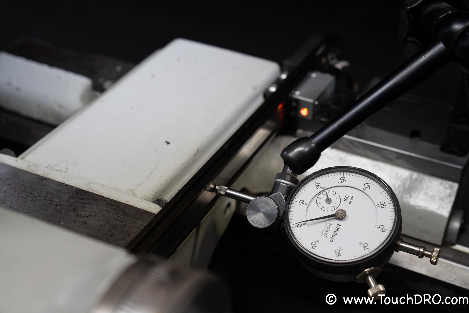
Checking DRO Scale Accuracy
Before spending an afternoon mapping a scale that doesn't need it, you can get a rough picture of all three errors without taking the scales off the machine. All it takes is a pair of 1-2-3 blocks and a tenths indicator, and the same basic measurement, with small variations, drives all three checks.
The Setup
Clamp one block (block A) to the table, and set the second block (block B) flush against it, with its 3" side along the axis you are checking. Mount a tenths indicator so it can reach the exposed face of block B. The setup will look similar to the photo below.
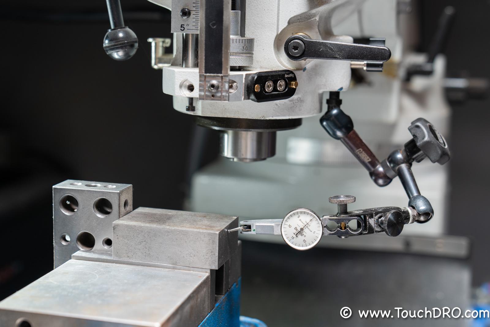
The basic measurement measures block B with the DRO, using the indicator to find the same two positions repeatably:
- Preload the indicator against block B and zero it out
- Zero out the DRO axis
- Remove block B
- Move the axis until the indicator preloads against block A and reads zero again
- Record the DRO reading
Since the indicator ends up exactly where the far face of block B used to be, the DRO has just measured the block's width. On a calibrated axis the reading should be 3.0000"; each check below is a variation of this measurement.
Repeatability
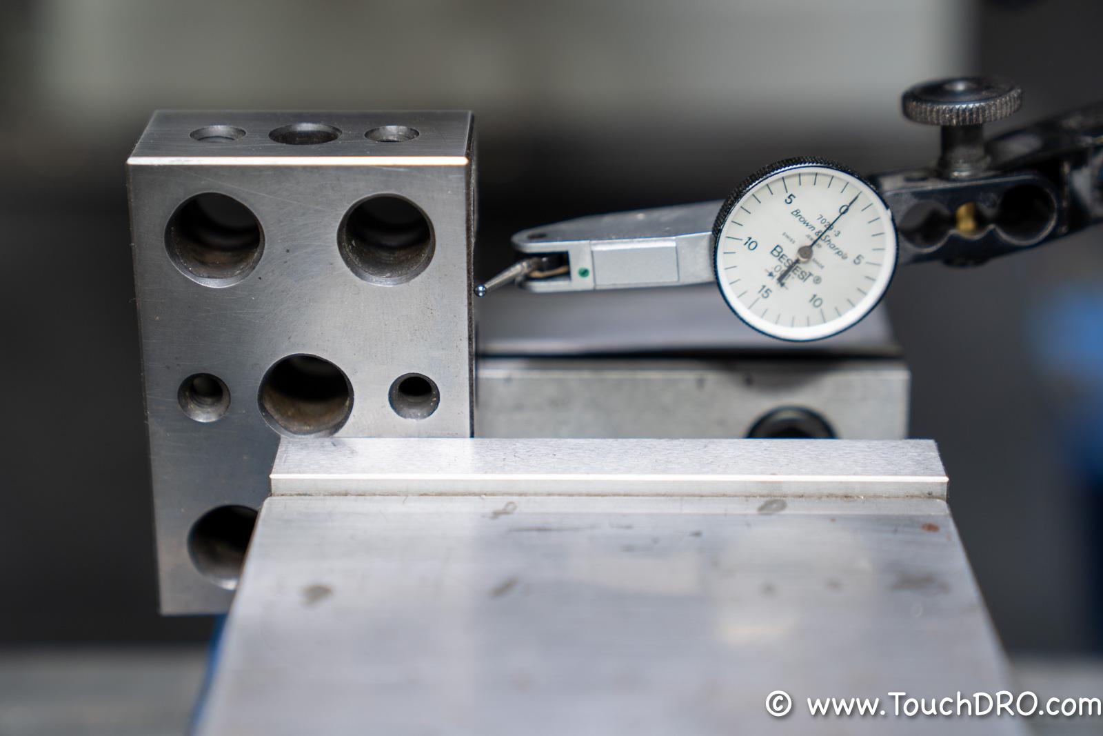
Let's start with repeatability, since it decides whether the other checks are worth running. Preload and zero the indicator against block B, and zero out the DRO axis. Move the axis away and back a few times, as fast as you safely can; some scales start dropping counts as the speed increases, and this is the check that catches it. Then bring the axis back until the indicator reads zero again, and note the DRO reading. It should be 0.
Repeat this a few times and write down the results. This is your repeatability error. On a good scale it will be zero, or at most one encoder count; on a 5-micron scale one count is about 0.0002", which is comfortably within reach of a tenths indicator.
If you see an error, try adjusting the scale's reading head before condemning the scale, paying particular attention to the gap between the head and the magnetic tape. An excessive gap hurts the signal-to-noise ratio the head sees, and the reading gets noisy before it fails outright.
If the error persists after the adjustments, you will need to decide whether you are comfortable with that amount of measurement uncertainty. No map can remove it: a scale that doesn't repeat its own readings limits everything else you do downstream.
Thermal Drift
The most practical way to measure thermal drift is to repeat the repeatability check in the morning, when the shop is cold, and again in the afternoon, when it's warmer. Write down the shop temperature both times; the difference is what gives the numbers meaning.
Strictly speaking, this measures the thermal drift of the whole setup, since the scale, the machine's castings, and the blocks all expand together. That combined number is the useful one, though: it tells you how tight your shop's climate control needs to be for the tolerances you want to hold.
Non-Linearity
To measure non-linear error, run the basic measurement three times, turning block B between runs so that each of its sides faces the indicator: measure the 3" side, the 2" side, and the 1" side, and write down all three readings. Ideally each should match its nominal size, but an uncalibrated axis might read something else. That is fine; this check cares about the variation, not the absolute numbers.
Now move the table by about half of the scale's pole pitch (2.5 mm, or roughly 0.1", for a common 5 mm scale) and measure the 3", 2", and 1" sides again from the new position. Three lengths, each measured at two positions half a pitch apart, land on different phases of the cyclic error, which is what makes it show up in so few readings; mapping the whole travel is the wizard's job, not the indicator's.
The step size matters more than the step count. The cyclic error repeats at the scale's pitch, so stepping by exactly one full pitch samples it at the same point in its cycle every time, and the largest error component becomes invisible. Half of the pitch is ideal, since it catches the error at its opposite extreme.
Two different errors will show up in the six readings. The part of the deviation that grows in proportion to the measured length is the linear error, and the normal calibration procedure removes it. The scatter that doesn't follow the length is the non-linear error, and that is the part only an error correction map can fix.
Comparing Two Scales Directly
The block checks sample the error at a handful of spots. When you have a second scale on hand, you can also see the error over the whole travel, live, and this is the same physical setup the error map process uses, so nothing about it is wasted work.
Mount the second scale parallel to the one being checked, the way "Mounting the Reference Scale" below describes, and connect it to a spare adapter input. Set both inputs to their correct resolutions, zero both displays at the same spot, and check that they count in the same direction. Then move the axis slowly along its travel and watch the two readouts: anywhere they disagree is error, with no arithmetic involved.
TouchDRO can even do the subtraction for you, and this part doesn't need Plus. In the axis settings, point a spare axis at the sum of the two inputs, with one input's counting direction reversed so that the pair cancels out, and zero the axis. That display now reads the disagreement between the scales directly: anything other than zero is error. If the sum grows as the axis moves instead of hovering near zero, the two inputs count in the same direction, and one of them needs its direction flipped.
What to Do with the Results
There is no single number that makes a scale good or bad. Look at the results and decide whether that amount of error is acceptable for the type of work you do; a scale that is marginal for chasing tenths may be perfectly fine for general machining.
Beyond that, the remedy depends on which check failed. There isn't much that can be done for stubborn repeatability error beyond adjusting the reading head, so it is the number to take most seriously. Thermal drift can be mitigated by keeping the shop temperature within a reasonable range, at least while precision work is being done.
The good news is that you can, with some work, remove a large portion of the non-linear error. It is compensated with an error correction map, often called interval-based calibration or segmented linear error compensation in DRO manuals. If you are using TouchDRO Plus, the rest of this guide shows how we mapped the cross slide scale on our own lathe. It is worth reading even if you run a different digital readout, since many consoles accept the same kind of correction table; the difference is that you will need to capture the deltas by hand and enter them into your console's memory.
Creating an Error Correction Map
Many modern digital readout consoles can correct non-linear error with an interval-based correction map. Unfortunately, creating one usually means tedious manual entry on the console's keypad, or specialized software that uploads the map over a USB or RS-232 port.
TouchDRO has a built-in Error Map Wizard that builds the map right in your shop, using a known-good scale as a temporary reference. In practice, a reasonably good import glass scale can remove a large portion of a magnetic scale's repeatable error. In broad strokes, the process is as follows. First, you mount the target scale in its permanent position and devise a way to zero it out repeatably. Second, you temporarily mount the reference scale parallel to it and connect it to a spare adapter input. Finally, you crank the axis back and forth a few times while TouchDRO records both scales, then review and save the map it builds. This guide walks that process on a real machine; the manual's "Creating an Error Map" page is the complete reference for it, from choosing a reference scale to reading the review figures.
A common use case for magnetic scales is the lathe cross slide. On many lathes with a 12" or smaller swing, there is not enough room on the cross slide for an optical scale, while the bed easily fits a full-size glass scale. Since any error on the cross slide is doubled on the part diameter, careful error correction is especially important here.
The rest of this guide walks through a real example: the cross slide scale on our Rockwell lathe. The scale has a nominal resolution of 1 micron, so I will use a 1-micron glass scale as the reference.
Establishing a Repeatable Zero
The error map is tied to the scale's own position counter, so the axis has to be zeroed at a spot you can come back to. Some mid-range import magnetic scales have reference marks every 50 mm, and TouchDRO can use them to create a durable zero point with the reference-mark routine. Otherwise, a hard stop at the end of the axis travel works: butt the axis against the stop and zero the counter from the "DRO Adapter Details" dialog.
Mounting the Reference Scale
Mount the reference scale parallel to the scale you are calibrating, lightly but firmly clamped; it needs to survive several passes without shifting. On the lathe, I clamped the glass scale across the ways and held the reading head in the tool post with a simple custom bracket, as shown in the photo below.
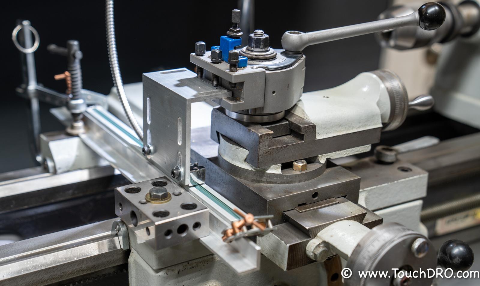
Ideally, the reference scale should cover the whole travel of the axis. When that is not practical, you can map the axis in sections and stitch the maps together; the manual's "When the Reference Scale Is Shorter" section covers how.
Plug the reference scale into a free adapter input (Z in this case), power up the TouchDRO adapter, and connect the app to it. The input has to be enabled: in its encoder settings, set the measurement mode to "Linear".
The "Lessons Learned" section at the end of this guide shows what a shifting mount does to the data.
Recording the Passes
First and foremost, zero out the target scale. This particular scale has reference marks every 50 mm, so I move the cross slide toward the front of the machine, start the reference-mark routine for the X input, and move the cross slide away until the mark registers. If your scale has no reference marks, butt the axis against the hard stop and zero the counter there instead.
To open the wizard, open the "DRO Adapter Details" dialog, press the gear button on the X input, then the button on the "Error Map" row, and finally the wand button in the map editor's toolbar. This opens the "Record Scale Error" dialog.
Set the "Reference input" to Z. Move the axis back and forth and make sure that both "Position" readouts follow, then crank the cross slide to its stop at the front of the machine.
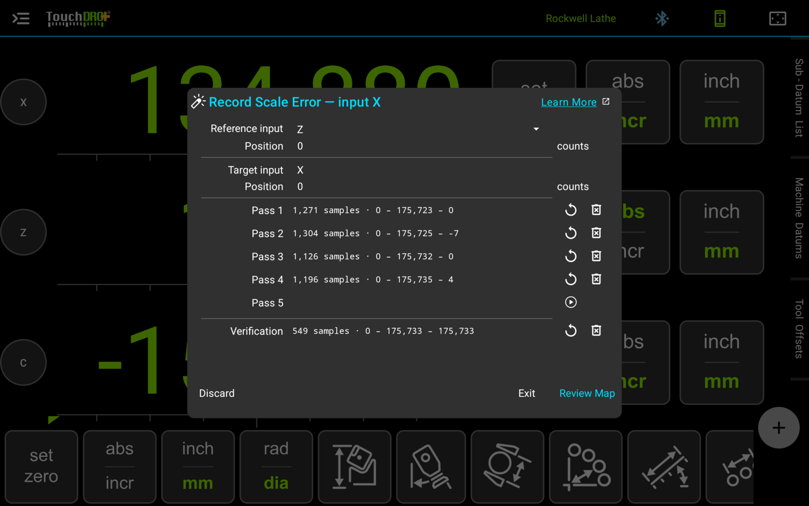
Now record the passes:
- Tap the play button on the first pass row
- Crank the cross slide to the far end of its travel and back to the stop, slowly and steadily
- Tap the stop button
- Repeat for the next pass
Slow and steady speed matters more than perfection: at roughly an inch every two seconds, the adapter's 25 readings per second land close enough together to capture the error in detail. If your lathe has a power cross feed, the lowest setting can work well, but listen for vibration; "Power Feed Vibration Creates Noise" below shows why. Pausing mid-pass to reposition your hand is completely harmless.
Two passes are the minimum TouchDRO needs to build a map, since it only trusts error that shows up in the same place on every pass. Passes three through five are optional, but each one gives the wizard more data to cross-check against, so the map gets a little better and the "Repeatability" figure on the review screen gets more trustworthy.
After the last pass, it's a good idea to run the "Verification" row the same way. TouchDRO will record one more pass and score it against the map built from the numbered passes, so you can see the leftover error before committing to anything.
Reviewing and Saving the Map
Any time after the second pass, you can tap "Review Map" to see the shape of the recorded error. The "Scale Error Review" screen shows the measured raw error, the error expected to remain after correction, and the improvement factor, over a plot of the recorded passes, the fitted map, and the verification result. The screen will look similar to the screenshot below.
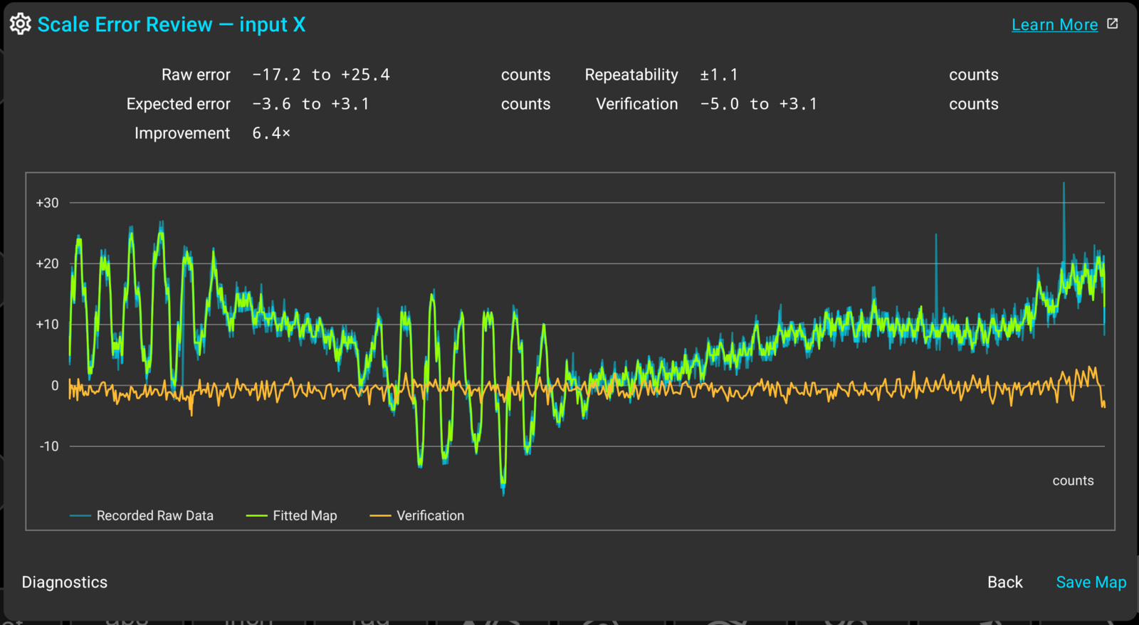
To write the map to the input, press "Save Map". From that point on, TouchDRO applies the correction to every reading from that scale, on every machine profile that uses it. What the individual figures mean, and the diagnostics behind them, are covered in the manual's "Reviewing the Results" section.
What Do the Results Mean?
Now that we have good data, let's talk about what it means. Frankly, this was a learning experience for us, since the error map is a brand new feature. We had measured this exact scale on a vibration-isolated optical bench against a 76 nm HeNe laser interferometer, where it showed less than 20 microns of total error. On the machine, the same scale measures 43: things like loose gibs, cross slide overhang, and even motor vibration affect the reading, and it took careful adjustment of the frame, the head spacing, and the gibs before the passes repeated well. More on that in "Lessons Learned" below.
As for what the numbers mean: the review figures are in encoder counts, and on a 1 micron scale a count is a micron, so the 43 microns of total error works out to almost 0.004" on the diameter across this cross slide's full travel. In practice the whole travel rarely matters at once; you re-measure and update presets at much smaller intervals, so the local error you actually feel is a fraction of that. Once corrected with the map, the verification pass put the residual at about 8 microns end to end, which drops into negligible territory for most lathe work.
The flip side is that the same error on a mill gets no such mercy. There is no re-measuring between the holes of a bolt pattern: uncorrected, a scale like this one could put two holes six inches apart nearly two thousandths off from each other, which is fatal for a precision jig or fixture.
Lessons Learned
Everything in this section comes from the first mapping sessions on our Rockwell lathe, which took more than a few hours. The error correction math was well understood and tested on the bench, but once we hit the real machine, things turned out to be much more interesting: when you are measuring single microns, small things matter.
For example, the gibs on our cross slide were a bit too loose, so the slide could shift sideways by a minuscule amount, and each turn of the crank telescoped through to the scale and disturbed the readings. The scale's frame was about 0.2 mm out of parallel, so the gap between the head and the tape grew by that much over the travel, which was enough to cause deep cyclic spikes, presumably from the interpolation circuit receiving a noisier signal. Neither problem was visible at the machine; both were obvious in the data, and each lesson below cost a recording of its own.
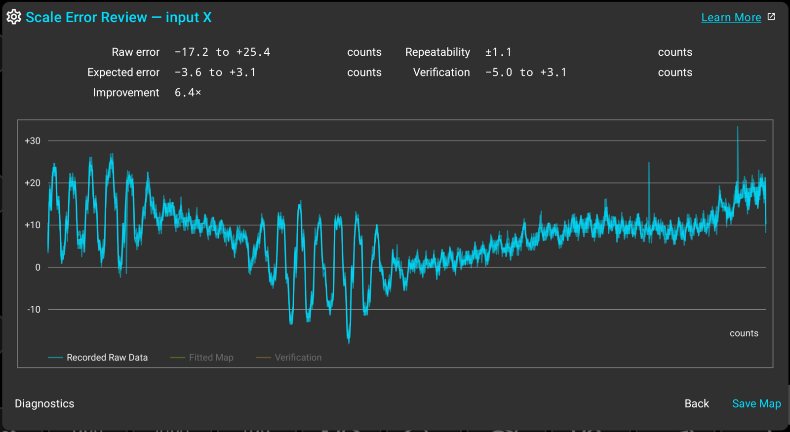
For contrast, this is what a good capture should look like. There is some noise, but the passes converge into one line. If you see strongly diverging lines instead, it's possible that your scale has poor repeatability, but a setup issue is more likely. We learned the hard way that the setup matters a lot in this process.
The Reference Scale Must Be Mounted Correctly
The screenshot below is the first real capture from that setup. The tape let the scale shift enough that the passes landed tens of counts apart, the repeatability read ±17.3 counts, and the map could promise only a 1.8× improvement. The other captures in this guide are the same setup, re-recorded after the scale was properly clamped.
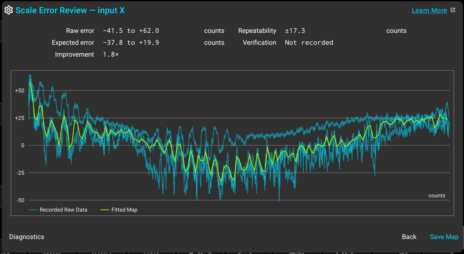
A mount that shifts doesn't announce itself. The machine feels the same, the readouts follow the axis, and every individual pass looks plausible on its own; the failure only shows when the passes are compared, which is exactly what the "Repeatability" figure and the stacked plot are for. If repeatability reads high and the passes sit apart, suspect the mount before the scale.
Power Feed Vibration Creates Noise
Power feed sounds like the obvious way to get a smooth, even crank, and most of the time it is. On our lathe, though, the feed set up a vibration once the carriage was extended about 80% of the way, and that stretch of the recording came back as a band of dense noise on every pass.
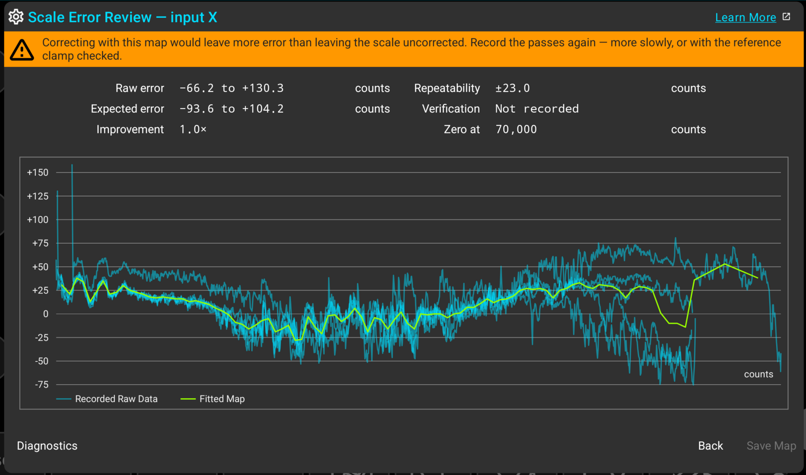
This is also the run where TouchDRO refused outright. With the noise counted as error, the map would have left more error than the bare scale, so the warning banner fired and "Save Map" stayed disabled.
More data doesn't fix this. The power-feed capture actually sampled denser than cranking by hand and still produced the worse map, because the noise went in with the samples. When a stretch of the plot looks fuzzy on every pass, listen to the machine at that position, and record by hand at a steady pace instead.
Cable Drag Corrupts Readings
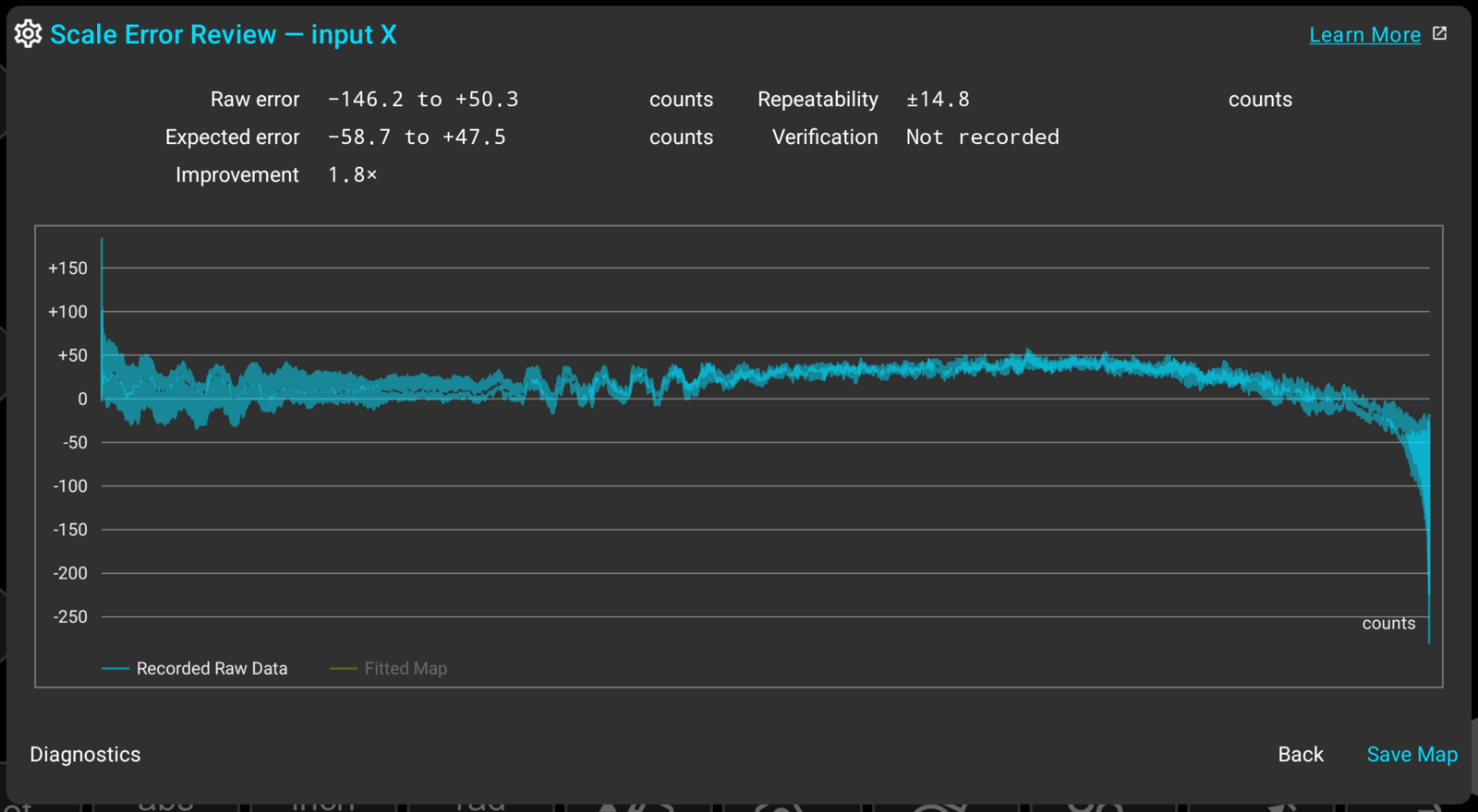
Both halves of the failure are on the plot. The jitter runs the whole travel, one burst for every rib that caught and released, and the plunge at the far end is where the cable finally pulled tight on the reading head. Twenty minutes of care per pass bought nothing, because care doesn't fix mechanics: a dragging cable loads the head sideways and unevenly, so the error lands somewhere different on every pass and no amount of slow, smooth motion averages it away.
Route the cable so nothing pulls on the head anywhere in the travel, strain-relieve it at both ends, and run the axis end to end while watching the cable before recording anything.
Frequently Asked Questions
[Expand]How accurate are magnetic DRO scales?
Resolution and accuracy are different things: a magnetic scale sold as 1 or 5 micron resolution can still carry much larger position error, since budget magnetic tape produces non-linear error an order of magnitude worse than a similarly priced glass scale. The 1 micron magnetic scale on our lathe's cross slide measured just over 40 microns (about 0.0017") of peak-to-valley error before correction, most of it a cyclic error repeating at the tape's pole spacing. After building an error correction map in TouchDRO, the same scale verified at roughly a sixth of that.
Can I calibrate a DRO scale without a laser interferometer?
Yes. Instead of an interferometer, you can clamp a more accurate scale (typically a glass scale) temporarily parallel to the axis and compare the two readings along the travel. TouchDRO Plus automates the whole process: the Error Map Wizard records both scales while you crank the axis back and forth, computes where the scale under test deviates, and builds the error correction map for you. On a conventional DRO console the same reference-scale method works, but you have to capture the deltas by hand and key them into the console's compensation table.
What is segmented linear error compensation (SLEC)?
Segmented linear error compensation, also called interval-based calibration, divides the scale's travel into intervals and applies a separate correction to each one, instead of the single scale factor that plain linear error compensation uses. That is what lets it correct error that changes along the travel, such as the cyclic error of magnetic tape, which no single correction factor can touch. TouchDRO implements it as an error correction map, and TouchDRO Plus can build the map automatically by measuring the scale against a temporarily mounted reference scale.
Why does my DRO read differently every time I return to the same position?
That is a repeatability problem, and it is almost always mechanical: a misaligned or badly spaced reading head, a loose scale mounting, or a cable dragging on the reading head. Check the head-to-scale alignment and spacing with a dial indicator before blaming the scale itself; a well-mounted scale should repeat within about one encoder count. Repeatability is worth fixing first because no error compensation of any kind can correct a scale that doesn't repeat its own readings.
Are cheap magnetic DRO scales worth using?
Yes, if you go in with open eyes. Budget magnetic scales usually repeat well and shrug off coolant and chips, and they fit where glass scales physically can't, such as a lathe cross slide. Their weak point is non-linear accuracy, driven mostly by the quality of the magnetic tape. On a DRO that supports segmented error compensation, such as TouchDRO Plus with its error correction maps, that error can be measured and largely removed: our budget 1 micron scale went from over 40 microns of error to single digits after mapping.