
Turning a Manual Mill into a Measuring Microscope
A measuring microscope, often sold as a "toolmaker's microscope", locates part features by sighting them through crosshairs over a precise XY stage. It is a wonderfully useful instrument for inspection and reverse engineering, but a new one costs thousands of dollars, and reasonably priced used units often come with expensive issues.
Your milling machine already has the precise stage. With an inexpensive USB microscope and TouchDRO, it can do most of the job for a fraction of the price. The microscope works as a convenient centering aid, and TouchDRO lets you capture coordinates, measure part features, and even export the captured geometry to your CAD software as a DXF file.
This guide covers the setup: mounting the camera, connecting it to the tablet, and teaching TouchDRO where the camera looks.
What You Will Need
The whole setup is inexpensive and mostly off-the-shelf. You will need:
- A USB microscope or camera that supports UVC - the "Recommended Microscopes and Cameras for Milling Machines" page covers how to choose one and lists the models we have tested
- A powered USB-C hub (tested hubs are on the same page)
- A way to mount the microscope to the machine head, with some means of adjusting the alignment
- TouchDRO Plus, included with current TouchDRO adapters
- Something with a straight, sharp corner for the alignment and offset steps - a vise jaw or a 1-2-3 block works well
Important Considerations
The mount has to meet up to three requirements, depending on how you plan to use the camera. It always needs to be sturdy. For accurate coordinates, the optical axis also needs to be parallel to the machine's Z travel. And if you plan to keep the stored offsets between sessions, the mount needs to be repeatable: it has to come back to the same position every time the microscope is removed and remounted. For digitizing work, where the whole part is measured in one session, repeatability doesn't matter.
Some setups are more challenging than others. On a Bridgeport-style head there is a lot going on, and finding a good mounting spot takes some creativity. On a smaller import tabletop or mini mill, the square head is much easier to work with, but the limited Y and Z travel can get in the way. It's best to look at the "Recommended Microscopes and Cameras for Milling Machines" page early to figure out what sort of microscope will fit your machine.
Mounting the Microscope
Designing and fabricating a mount for the microscope is likely going to be the most time consuming part of this project. While there are no external forces pushing on the camera, the mount needs to be sturdy enough to eliminate any wobble or image shift while focusing. Close-up macro lenses and microscope objectives have an extremely small depth of field, sometimes measured in tens of microns, so you will be refocusing a lot. A wobbly mount will make this difficult, and will likely shift each time you touch the focusing ring.
The other important design consideration is vertical alignment. The microscope's optical axis must be strictly parallel to the Z axis, or the image will shift due to parallax error each time you move the head or the table up or down. A good starting point is a ring with three sets of jack and set screws that you can glue or clamp to the microscope, and a holder arm with some sort of quick detachment mechanism that will let you remove the microscope while machining.
For best repeatability, a magnetic kinematic base or a similar setup would be ideal, but magnets and metal chips don't mix well. On our mill, we used a short NATO rail and a lever-type NATO clamp. These are commonly used in video camera rigs, and are readily available on Amazon and other online marketplaces for very reasonable prices. While in theory not as repeatable as a kinematic base, our clamp setup has worked very well so far. A Picatinny rail with a quick-release clamp is another compact option.
Some cheaper microscopes don't show crosshairs, and others call them "guide lines" that need to be manually enabled and positioned on the screen. If you feed the video into TouchDRO, this doesn't matter, since the application draws its own crosshairs. For standalone use, you will need the on-screen kind, or a bit of improvisation.
Aligning the Microscope
First, set the horizontal angle, so the crosshairs are parallel to the axes of travel. Move the table along one axis and watch a feature cross the screen. Rotate the microscope in its mount until the feature tracks along the crosshair line.
Next, align the optical axis vertically. Move the crosshairs over a sharp edge (a vise jaw, for example) and lower the microscope as far down as it will go while still able to focus. Align the crosshairs with the edge, then move the head up (or the table down), refocus, and check that the crosshairs are still on the edge. If they moved, adjust the vertical alignment and try again. You should see no horizontal movement between the upper and lower limits of travel.
Checking Mount Repeatability
This check only matters if you plan to indicate workpieces against stored offsets, so skip it for digitizing-only use. Indicate a feature and note the coordinates. Remove and remount the camera, then indicate the same feature again. The difference between the two readings is the mount's repeatability. If the numbers move more than you care about, the mount is still fine for digitizing, but the offsets will need to be recaptured whenever the camera is remounted.
Connecting to TouchDRO
Some microscopes and cameras will work plugged straight into the tablet, but many of the Chinese camera chipsets are not true USB 3 and won't work over a USB-C to USB-C cable. The camera is simply never detected. In general, it is better to connect through a powered USB hub, like the one in the photo below. Besides taking care of the USB protocol incompatibility, the hub also powers the tablet and supplies extra current to cameras that need it.
After plugging the camera in, give it time to appear. Some models take tens of seconds to show up, and replugging restarts the wait. Once the camera is detected, use TouchDRO's "Camera Setup" dialog to test its video modes and save one that works: many cameras advertise modes they can't actually deliver, and a mode that is too ambitious for the tablet will lag. Judge the modes with the camera pointed at a real, textured part, and if the picture lags, pick a lower resolution. The "Live Camera Feed" page describes the "Camera Setup" dialog in detail.
Setting Up the Profile
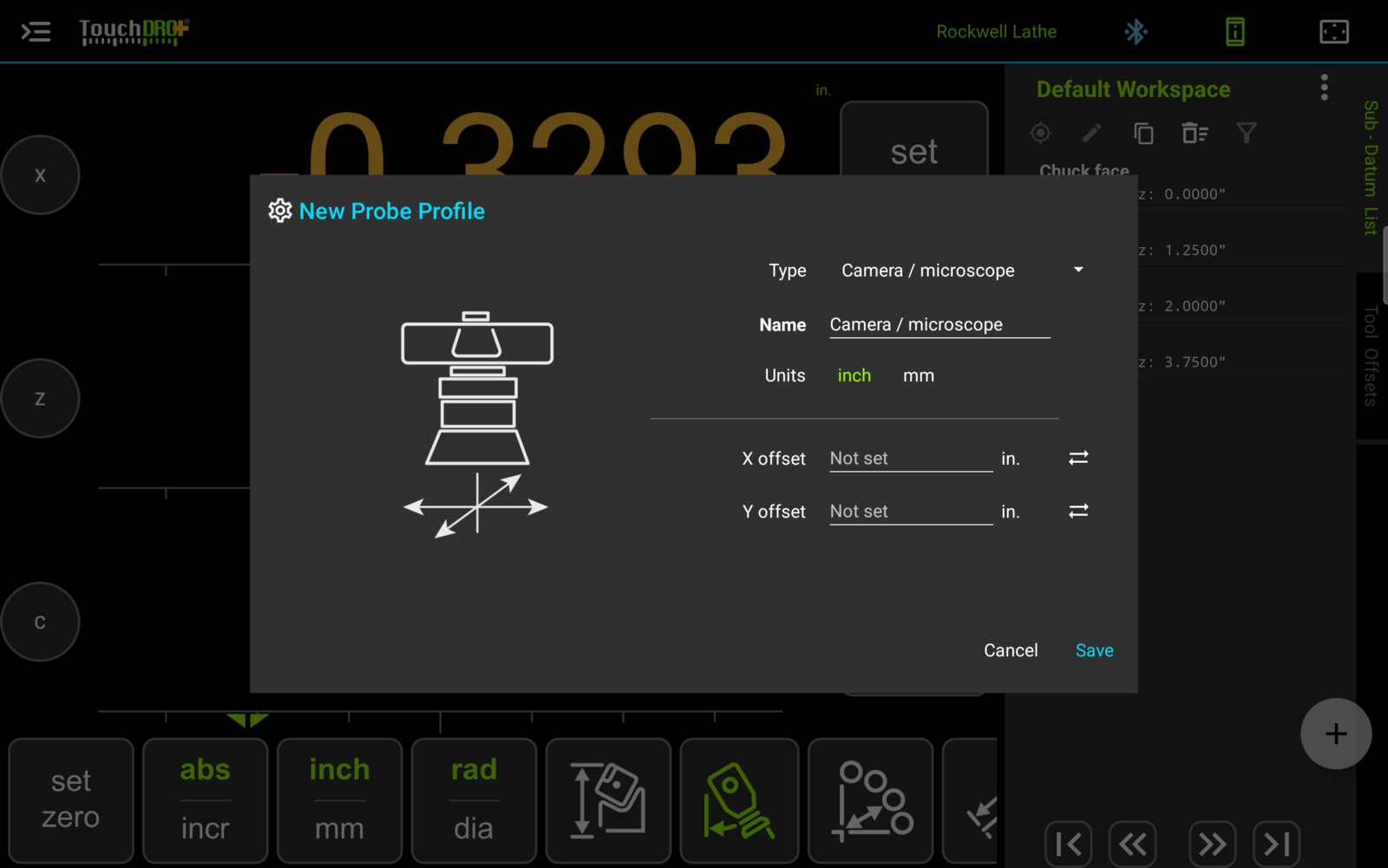
TouchDRO needs to know where the camera is looking in relation to the spindle axis. To store that offset, you create a profile for the camera in the "Probe Library", just like for a touch probe. The profile holds the offset between the crosshair and the spindle, and TouchDRO will apply it to every coordinate you capture.
Rather than measuring the offset and typing it in, you can have TouchDRO read it directly: set the origin on a point you can identify precisely, then park the crosshair on the same point and capture the current position.
- Indicate a corner of a vise jaw, a 1-2-3 block, or anything else with two straight sides, and set the origin at that corner. The "Indicate Workpiece" function will set the origin exactly on the corner.
- Move the camera over the same corner and align the crosshair with the two sides.
- Without moving the table, open the "New Probe Profile" dialog in the "Probe Library".
- Set the type to "Camera / microscope".
- Enter a name, or keep the default if it suits you.
- Select your preferred units.
- Tap the sync buttons next to "X offset" and "Y offset". Each one will take the current reading for that axis.
- Tap "Save".
With the profile saved, the setup is done, and the mill is a measuring microscope. The "Reverse Engineering a Part with a Digital Microscope" guide walks through putting it to work on a real part.