
Adding a Spindle Tachometer to TouchDRO
If your lathe or mill has a step pulley or a gearbox, you can get the spindle speed from the chart on the machine. With a variable frequency drive, a DC motor controller, or a variable speed head, you often don't know how fast the spindle is actually turning. The drive shows you a frequency or a dial position, and you still need to account for the belt ratio to get the spindle speed.
With a tachometer connected to TouchDRO, you can see the actual spindle speed on the main screen while the machine is running. On a lathe, you can switch the readout to surface speed, which is calculated for the diameter the tool is at, and adjust the drive to hold it as you face or part off. You can also check the thread pitch that the carriage is feeding at before you cut a thread, which confirms that the gearbox or the change gears are set correctly. On a mill with a power feed, you can use the chip load readout to set the feed rate to match the chip load recommended for the cutter.
Unfortunately, machines differ too much for a turn-key tachometer that will "just work" on all of them, so you will need to build your own. The electronic part is pretty straightforward, since all you need is an inexpensive sensor and a three-wire cable. You will likely spend most of the effort on choosing a sensor that suits your machine and on finding a way to mount it. This guide will help you choose the sensor, build the tachometer, and connect it to TouchDRO.
What You Are Building
A tachometer has three parts: something that turns with the spindle (one or more magnets, or a disk with slots), a sensor that produces an electrical pulse each time a magnet or a slot passes it, and a cable to the adapter's tachometer input. TouchDRO measures how often the pulses arrive and divides by the number of pulses per revolution to get the RPM.
All current TouchDRO adapters (the TDA-410, the TDA-420, and the TDK-40 kit) have a tachometer input. The input uses a standard Mini-DIN 4 connector and supplies 5V to power the sensor. The TDA-410 comes with one spare Mini-DIN 4 plug and the TDA-420 comes with two. If you built the adapter from the TDK-40 kit, you will need to buy a plug.
Note that the wiring and setup sections below are specific to TouchDRO adapters, but the advice on choosing and mounting a sensor applies to any tachometer display that takes a 5V pulse input.
You will need a soldering iron with a fine tip, a multimeter, and the usual tools for making a small bracket. The connector pins are small and close together, so reasonably good soldering skills help. An oscilloscope is convenient for troubleshooting, but you can get by without one.
Choosing a Sensor
There are three inexpensive sensor types that work well for a spindle tachometer: a Hall effect "barrel" sensor, a Hall effect sensor on a small circuit board, and an optical slot sensor. The first two detect a magnet, and the third one detects the slots in a disk. Which one you should use mostly depends on how many pulses per revolution you need, and on how dirty and how cramped the place for the sensor is.
How Many Pulses per Revolution
The simplest tachometer produces one pulse per revolution, from a single magnet. This works well from about 120 RPM and up. Below that, the pulses arrive less than twice a second, and the reading becomes slow to update and less steady. The adapter will still count pulses that are up to 2 seconds apart, which is 30 RPM with one pulse per revolution, but that close to the limit the reading is too sluggish to be useful.
To get a good reading at lower speeds, you need more pulses per revolution. You can add more magnets, but this helps only to a point. At low RPM, TouchDRO measures the time between pulses, and since no two magnets are exactly alike, the pulses are never perfectly evenly spaced. As a result, the reading from several magnets tends to jump around at very low speed. A slotted disk doesn't have this problem, and with 20 or more slots the reading will be steady at any speed a manual machine can run.
This is important if you thread in back gear on a lathe, turn large diameters, or run a large fly cutter or a boring head at low speed on a mill. If your spindle never runs below a couple hundred RPM, one pulse per revolution is enough.
High spindle speed is not a problem for either sensor type. The adapter accepts up to 100 kHz. For comparison, a 60-slot disk turning at 6,000 RPM produces only 6 kHz.
Hall Effect Barrel Sensors
A barrel sensor is a threaded metal or plastic cylinder, usually M12, with the Hall effect sensor sealed in the tip and a cable coming out of the back. The NJK-5002C is the one you will see most often. It is sold as an industrial proximity sensor, and it comes with two nuts, so you can mount it in a hole in a simple bracket and adjust the gap by turning the nuts.
The sensor is fully sealed. Oil, coolant, and chips have no effect on it, which makes it a good choice for an exposed location. The body is about 1/2" (12 mm) in diameter and 1-1/2" (40 mm) long, plus the bend in the cable, so it needs some room behind the bracket.
The main drawback of these sensors is that many of them are advertised as "5V-24V" but don't work reliably at 5V, and there is no way to tell except to try. This is covered in "Checking the Sensor at 5V" below, and you should read that section before you order one.
Barrel sensors are sold in "NO" (normally open) and "NC" (normally closed) versions. You can use either one, since TouchDRO counts the rising edge of each pulse and it doesn't matter whether the sensor is normally on or normally off. Make sure to get an NPN sensor, which is by far the most common type. PNP sensors will not work.
Hall Effect Sensor Boards
A sensor board is a small circuit board, sold for hobby electronics projects, with a Hall effect sensor at one end, an indicator LED, and three pins: power, ground, and signal. These boards are designed for 5V, so the supply voltage is not a problem. They are also much smaller than a barrel sensor, and you can fit one into a gap that is less than 1/4" (6 mm) deep.
Oil and chips don't affect the Hall effect sensor itself, the same as with the barrel type. On the other hand, the board is bare electronics, and you will need to protect it. A piece of heat shrink tubing over the whole board or a coat of epoxy is usually enough. You will also need to make your own mount, since the board has one small screw hole at best.
Optical Slot Sensors
An optical slot sensor (also called an "optointerrupter") is a U-shaped part with an infrared LED in one leg and a light detector in the other. A thin disk with slots or holes near its rim turns through the gap, and the sensor produces a pulse for every slot. The sensors are sold on small boards with the same three pins as the Hall effect boards, and they also run on 5V.
An optical sensor works much better than a Hall effect sensor when you need a high number of pulses per revolution. A slot can be very narrow, so you can fit 20, 30, or 60 of them on a small disk, and it's not hard to space them evenly. As a result, the RPM reading is steady across the whole speed range, including very low speeds. You can't do this with magnets, because closely spaced magnets interfere with each other.
On the other hand, an optical sensor needs more space and is more sensitive to dirt. You will need room for the disk on the spindle and for the sensor that straddles its rim. In addition, the light path has to stay clear, so you will need a cover that keeps chips, oil, and coolant away from the sensor. In a dry, enclosed location, such as the outboard end of a lathe spindle or under the belt cover of a mill, this takes very little effort.
Which One to Choose
| Hall effect barrel sensor | Hall effect sensor board | Optical slot sensor | |
|---|---|---|---|
| On the spindle | One or a few magnets | One or a few magnets | Slotted disk |
| Pulses per revolution | 1 to 4 | 1 to 4 | 20 to 60 or more |
| Steady reading from | About 120 RPM with one magnet | About 120 RPM with one magnet | A few RPM |
| Oil, coolant, and chips | Sealed, not affected | Not affected once the board is covered | Needs a cover |
| Space needed | 1/2" (12 mm) barrel, 1-1/2" (40 mm) long | Very little | Room for the disk and the sensor around its rim |
| Works from 5V | Not always, check before mounting | Yes | Yes |
If your machine runs at a few hundred RPM and up, a Hall effect sensor with a single magnet is a solid choice and the least amount of work, since you only need to drill one shallow hole in a pulley and make one bracket. Use a barrel sensor if the location is exposed and you have room for it, or a sensor board if space is tight.
If you often run the spindle at low speed, an optical sensor with a slotted disk is the better choice. In our experience, it gives a much steadier reading at low RPM than a Hall effect sensor with several magnets. It is more work, since you will need to make a disk and a cover.
Building a Hall Effect Tachometer
A Hall effect tachometer consists of one or more small magnets attached to something that turns with the spindle, and a sensor on a bracket that faces them across a small gap.
Parts for a Hall Effect Tachometer
- An NPN Hall effect barrel sensor or a Hall effect sensor board.
- One or more neodymium disk magnets. A magnet 1/4" (6 mm) in diameter and 1/8" (3 mm) thick is a good size.
- Three-conductor cable, preferably shielded, long enough to reach the adapter. Most barrel sensors come with about 6 feet (2 m) of cable attached.
- A Mini-DIN 4 male plug.
- Epoxy for the magnets, and material for a bracket.
Checking the Sensor at 5V
If you are using a barrel sensor, test it at 5V before you make any brackets. The Hall effect device inside these sensors is a 5V part that needs at least 4.4V to 4.6V to operate, and there is a diode in line with the supply wire that drops a part of the supply voltage. The sensors were originally designed for systems that run on 6V or more, where this doesn't matter. When powered from 5V, the device gets just about the minimum it needs, and whether a particular sensor works depends on how the tolerances of its parts happened to line up.
In other words, a "5V-24V" label on one of these sensors is optimistic. Some of them work at 5V, some don't, and some work on the bench and then drop out when the temperature changes. Note that the problem is in the design of the sensor, so if you replace it with another one of the same model, the new one might or might not work any better.
To test the sensor, wire the connector as described in "Wiring the Connector" and follow the steps in "Testing on the Bench". If the signal doesn't switch cleanly every time you pass a magnet in front of the sensor, don't use that sensor. Sensor boards and optical sensors are designed for 5V and don't have this problem.
Placing the Magnets
The magnets have to turn with the spindle itself. On a belt-driven machine, a magnet on the motor pulley or on an intermediate shaft will give you a reading that is off by the belt ratio, and the ratio changes every time you move the belt. You can usually find a suitable place on the spindle pulley, on the outboard end of a lathe spindle, or on a collar at the top of a mill spindle. On a mill, choose a part that doesn't move up and down with the quill.
For a single magnet, drill a shallow flat-bottomed pocket, set the magnet into it flush with the surface, and fix it with epoxy. Don't rely on the magnet's own pull to hold it on a steel part, since a magnet that comes off a spinning pulley becomes a projectile.
Most Hall effect sensors respond to only one pole of the magnet. Before you glue anything, hold the magnet in front of the powered sensor and check which face switches it (the indicator LED on a sensor board will show you, and for a barrel sensor you can use a multimeter). Mark that face, and install every magnet with the marked face toward the sensor.
If you are using more than one magnet, the following points are important:
- The magnets need to be evenly spaced. TouchDRO expects the pulses to be the same distance apart, and with uneven spacing the reading will jump around even when the speed is steady. To get the spacing right, you can lay the pockets out on the mill with the "Hole Circle" function.
- Set all of the magnets to the same depth and with the same pole facing out, so that each one switches the sensor at the same point.
- Don't put the magnets too close together, since the magnetic field has to drop off between two magnets before the sensor can switch off. On a small pulley, four magnets is about the practical limit. If you need more pulses than that, an optical sensor is a better choice.
Note that even with careful work, the magnets will not be perfectly matched, and with several magnets the reading tends to jump around at very low speed. This is covered in "Unstable Reading at Low Speed".
A single small magnet will not upset the balance of a pulley on most machines. On a small, fast spindle it's better to use two magnets opposite each other and set the pulses per revolution to 2.
In addition, keep in mind that an exposed magnet collects steel chips. They don't affect the sensor directly, but a large enough clump will eventually bridge the gap and rub on it. This is one more reason to put the magnet under a belt cover or at the far end of the spindle, away from the cut.
Mounting the Hall Effect Sensor
The sensor needs to face the path of the magnet squarely, with a small gap. A barrel sensor will detect a small neodymium magnet from as far as 3/8" (10 mm) away, but you will get the most consistent switching with a gap of about 1/16" to 1/8" (2 to 3 mm). A sensor board needs to be about that close as well.
For a barrel sensor, the bracket can be a piece of angle or flat bar with a 12 mm (or 1/2") hole. Thread one nut on each side of the bracket, set the gap, and tighten them against each other. For a sensor board, the sensor is the small black part at the end of the board, and its flat marked face should point at the magnet. Make the bracket rigid enough that vibration doesn't change the gap.
Building an Optical Tachometer
An optical tachometer consists of a thin slotted disk on the spindle and a slot sensor mounted so that the rim of the disk passes through its gap.
Parts for an Optical Tachometer
- An optical slot sensor board with a digital output (usually marked "DO" or "OUT").
- An encoder disk that fits your spindle, as described below.
- Three-conductor cable, preferably shielded, long enough to reach the adapter.
- A Mini-DIN 4 male plug.
- Material for a sensor bracket and a cover.
These boards are sold without any specifications. The parts on them should switch at many kHz, which is far more than a spindle tachometer needs, but there is nothing on paper that guarantees it for a particular board. For that reason, it's a good idea to check the reading at your top spindle speed once the tachometer is installed. The same is true for the Hall effect sensor boards.
Making the Encoder Disk
The encoder disk is a thin disk with evenly spaced slots or holes near the rim. It needs a bore that fits your spindle (or a hub that does), and it has to run true enough to pass through the sensor's gap without rubbing. The gap on the common sensor boards is about 3/16" (5 mm) wide, so this is not hard to achieve.
For most machines, a disk with 20 to 60 slots is a good choice. With more slots you will get a steadier reading at low speed, and there is no penalty at high speed. Make the slots and the bars between them about the same width, and no narrower than about 1/16" (1.5 mm), since very fine slots require more careful alignment of the sensor.
Before you decide on the disk diameter, look at your sensor. The slots need to pass between the two small windows on the inside faces of the sensor, which are a few millimeters in from the open end of the gap.
Note that the sensor uses infrared light, and some plastics that look opaque let it through (thin 3D prints in particular). Sheet metal is the safe choice. If you want to use plastic, pass a scrap of it through the sensor first and check that the output switches.
The easiest way to make a disk in a home shop is to drill a circle of holes in a piece of thin aluminum or steel sheet. A hole works just as well as a slot. Using the TouchDRO "Hole Circle" function, you can drill 30 evenly spaced holes on a mill in a few minutes, and then turn or cut the outside to size. A disk can also be laser cut or 3D printed (keeping the note about the material in mind).
Mounting and Covering the Optical Sensor
As with the magnets, the disk has to be on the spindle itself. On a lathe, the outboard end of the spindle is usually the best place, since it is away from the chips and often has a thread or a bore that you can use to hold a hub. On a mill, look for room at the top of the spindle or above the spindle pulley, on a part that doesn't move with the quill.
Mount the sensor on a rigid bracket so that the disk runs in the middle of the gap. To check the alignment, turn the spindle slowly by hand and watch the indicator LED on the sensor board (or a multimeter on the signal wire). It should switch cleanly once for every slot, all the way around.
After that, cover the sensor and the disk. The cover doesn't need to be sealed, as long as it keeps chips from landing in the gap and keeps oil and coolant spray off the two small windows inside it. A piece of bent sheet metal or a 3D-printed shroud is enough in most locations. If the readout becomes erratic months later, a dirty sensor is the first thing to check, and a cotton swab with some alcohol will usually fix it.
Wiring the Connector
The tachometer input needs three connections: ground, 5V power for the sensor, and the signal. The input is pulled up to 5V inside the adapter through a 10K resistor, and it expects the sensor to pull the signal below 1.1V and let it rise above 2V. NPN (open collector) and push-pull outputs both do this. All of the sensors described above are one of those two types.
The signal is on a different pin depending on the adapter:
| Pin 1 | Pin 2 | Pin 3 | Pin 4 | |
|---|---|---|---|---|
| TDA-410 and TDA-420 (Aux. 2 port) | Ground | 5V | Signal | --- |
| TDK-40 | Ground | 5V | --- | Signal |
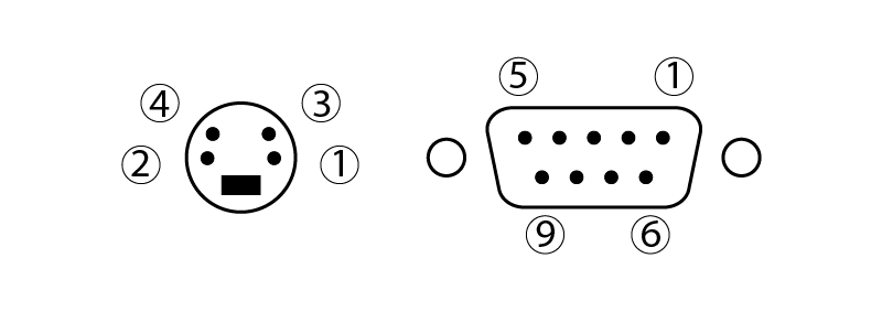
On the sensor side, you will need to identify the same three connections. On a sensor board, the pins are marked on the board: "GND" for ground, "VCC" or "+" for 5V, and "DO" or "OUT" for the signal. On a barrel sensor, the wiring diagram is printed on the label or on the body of the sensor, and it shows which wire is the positive supply, which is ground (often marked "0V" or "-"), and which is the output.
To start, slide the plug's strain relief boot and outer shell onto the cable. This is easy to forget, and once the wires are soldered the only fix is to take them off again.
After that, strip about 3/4" (20 mm) of the outer jacket and about 1/8" (3 mm) of each wire, and tin the wire ends. The pin numbers are molded into the plastic insert of the plug next to each solder cup. Keep in mind that you are looking at the plug from the back, so the layout is a mirror image of Fig. 1.
Once the wires are tinned, solder each one into its solder cup. A short piece of small heat shrink tubing over each joint will keep the pins from shorting to each other or to the metal shell. If your cable has a shield, connect it to the ground pin at this end only, and leave it unconnected at the sensor.
Before you close the plug, use a multimeter to check that none of the pins are shorted to each other, and that each wire goes to the pin you intended. If you are using a barrel sensor, do the bench test described below at this point as well, since this is the last time you can reach the pins. Then assemble the shell and crimp the strain relief around the cable jacket.
Adding a Pull-Up Resistor
In many cases you will get a cleaner signal with a stronger pull-up than the one built into the adapter, especially with a barrel sensor, a long cable, or a machine with a variable frequency drive. To add one, solder a 4.7K resistor between the 5V pin and the signal pin. With some care, you can fit the resistor inside the plug.
Use a small 1/8W or 1/4W resistor. Trim its leads short, solder one lead to the 5V pin and the other to the signal pin together with their wires, and insulate the leads so that they can't touch the ground pin or the shell. If you prefer, you can put the resistor at the sensor end of the cable, where there is more room.
You can build the cable without the resistor and add it later if the reading turns out to be unstable.
Testing on the Bench
It's much easier to find a problem on the bench than after the brackets are made, so test the sensor as soon as the wires are soldered. Plug the connector into the adapter's tachometer input and power the adapter. Set a multimeter to DC volts and measure between signal and ground. On a sensor board you can measure at the board's own pins. With a barrel sensor, measure on the back of the plug before you fit the shell.
Now pass the magnet in front of the Hall effect sensor, or a strip of sheet metal through the gap of the optical sensor. The reading should switch between close to 0V and close to 5V. It doesn't matter which of the two states is "on", as long as the low level is well under 1V, the high level is well over 2V, and the sensor switches every time.
If the voltage doesn't change, flip the magnet over and try the other face. If a barrel sensor still doesn't switch, or switches only some of the time, it most likely doesn't get enough voltage at 5V (see "Checking the Sensor at 5V").
Setting Up TouchDRO
Once the sensor is installed and plugged in, there are three settings to check in TouchDRO.
To start, connect to the adapter and open the "DRO Adapter Details" dialog. On a TDA-410 or a TDA-420, the sensor is connected to the "Aux 2" input, and its input mode needs to be "Tachometer", which is the default.
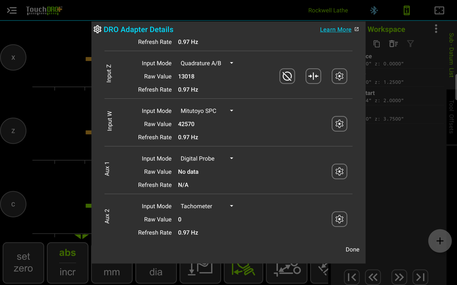
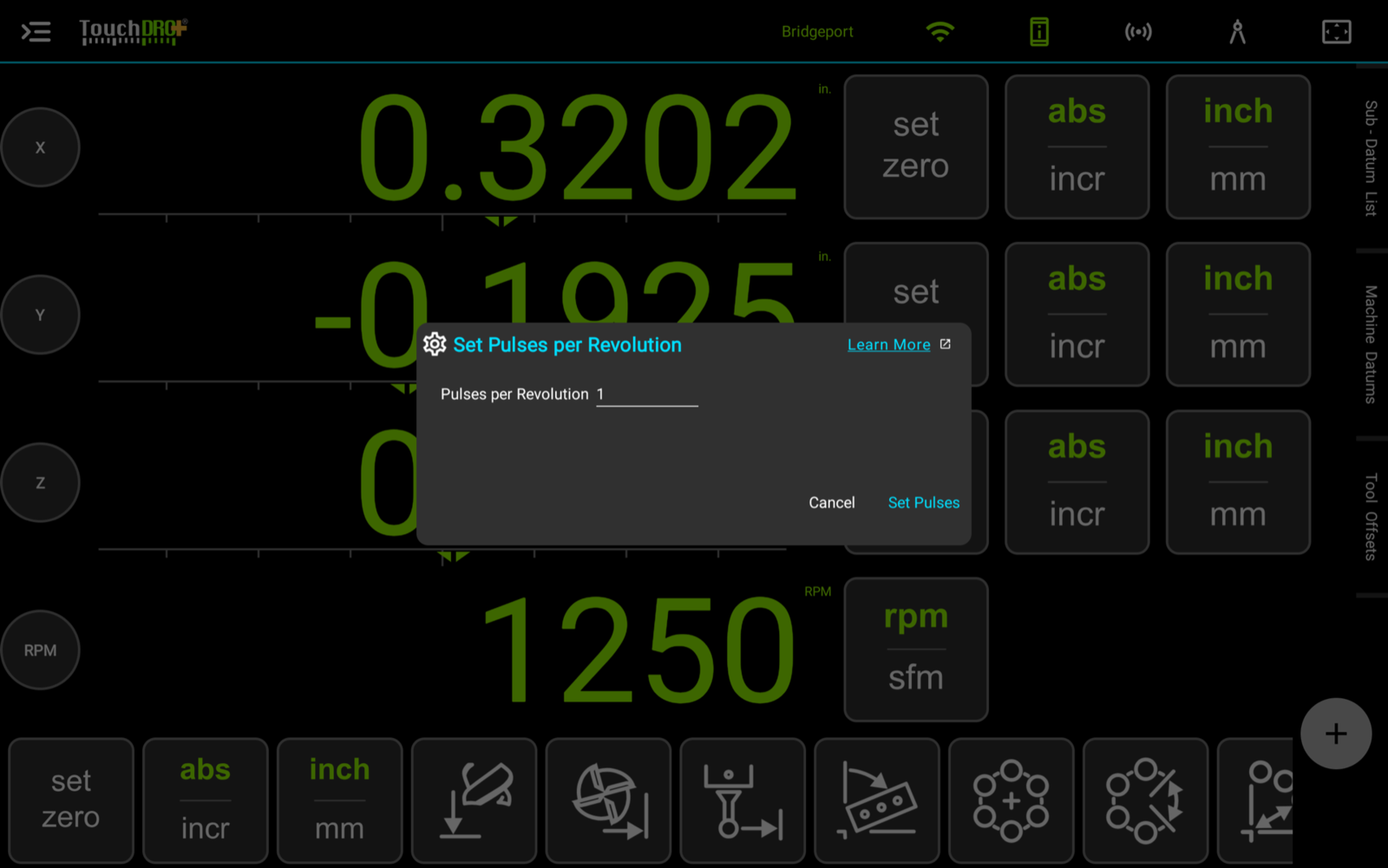
After that, tap the gear button on the tachometer input's row. This will open the "Set Pulses per Revolution" dialog. Enter the number of magnets or the number of slots in your disk, and press "Set Pulses".
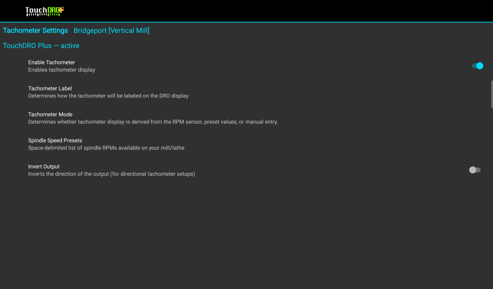
Finally, open the application menu, tap "Settings", and tap "Tachometer Settings". Turn on "Enable Tachometer", and make sure that "Tachometer Mode" is set to "Read from RPM Sensor".
At this point the RPM readout will appear on the main screen. Start the spindle at a speed you know, such as a belt position from the machine's speed chart, and compare. If you have a handheld tachometer, use it to check the reading at the lowest and the highest speed you normally use.
Troubleshooting
Most problems with a new tachometer fall into one of the following groups: there is no reading at all, the reading becomes unstable as the spindle speeds up, the reading jumps around at very low speed, or the reading is steady but doesn't match the speed you expect.
No RPM Reading
If the RPM readout doesn't change when the spindle is running, go through the following checks in order:
- Check the settings described in "Setting Up TouchDRO". The input mode needs to be "Tachometer", "Enable Tachometer" needs to be on, and "Tachometer Mode" needs to be set to "Read from RPM Sensor".
- Check that the sensor is plugged into the correct port. On a TDA-420, the two Mini-DIN ports are identical, and the tachometer needs to be in the one marked "Aux. 2".
- Check that the sensor switches. Turn the spindle slowly by hand, and watch the indicator LED on the sensor board or measure the signal with a multimeter, as described in "Testing on the Bench".
- If the sensor switches and there is still no reading, check the wiring of the plug. The signal needs to be on pin 3 for a TDA-410 or a TDA-420, and on pin 4 for a TDK-40.
If the sensor doesn't switch, the usual causes are a gap that is too large or a magnet that is installed with the wrong pole facing the sensor. With a barrel sensor, the most likely cause is that the sensor doesn't work at 5V (see "Checking the Sensor at 5V"). With an optical sensor, check that the slots line up with the sensor windows, and that the disk is not made from a plastic that lets infrared light through.
If the tachometer works when you install the sensor and then stops reading on a cold morning, or after the machine has been running for a while, this is also a sign of a barrel sensor that is not getting enough supply voltage. Note that adjusting the gap will not fix this.
Unstable Reading at High Speed
As the spindle speeds up, the pulses get shorter and closer together, and a signal that was good enough at low speed can become marginal. As a result, the reading starts to jump around or drops out completely above a certain speed. In most cases you can fix this with one of the following:
- Add the 4.7K pull-up resistor described in "Adding a Pull-Up Resistor", if you haven't already. In many cases this is enough.
- Set the sensor closer to the magnets. With a small gap the sensor switches earlier and stays on longer as the magnet passes.
- If you are using several magnets, check that they are far enough apart for the sensor to switch off between them.
- With an optical sensor, clean the sensor windows and check that the disk doesn't wobble in the gap. If the slots are very fine, the sensor needs to be aligned more carefully.
If the reading goes wild as soon as the motor starts, or gets worse as you turn up a variable frequency drive, the cause is most likely electrical noise. To reduce it, route the sensor cable away from the motor leads and the drive, and don't run it in the same conduit or cable tray. It also helps to use shielded cable with the shield connected to ground at the adapter end.
Unstable Reading at Low Speed
If you are using more than one magnet, a reading that jumps around at very low speed is very common. At low RPM, TouchDRO measures the time between pulses. The strength, the spacing, and the orientation of the magnets always vary slightly from one magnet to the next, so the sensor doesn't switch at exactly the same point for each of them. As a result, the pulses are not evenly spaced, and the RPM jumps from one pulse to the next, often quite noticeably. The reading settles as the speed goes up.
You can reduce the effect by using magnets from the same batch, setting them to the same depth, and spacing them as accurately as you can, but you will not be able to remove it completely. If you need a steady reading at very low speed, use an optical sensor with a slotted disk. With a single magnet the pulses are always exactly one revolution apart, so the reading doesn't jump, but it is slow to update below about 120 RPM.
If the reading also jumps around at higher speeds, look for a magnet that is clearly out of place, or one that is set deeper or is weaker than the others.
RPM Is Off by Some Percentage
If the reading is steady but different from the speed you expect, start by looking at how far off it is.
If the reading is off by a simple fraction, the number of pulses most likely doesn't match the "Pulses per Revolution" setting. For example, if the reading is exactly double or half of the real speed, count the magnets or slots again and correct the setting. If you have four magnets and the reading is 25% low, the sensor is missing one of them, most likely because that magnet is installed with the wrong pole facing out or is set too deep. If the error changes when you move the belt, the magnets or the disk are on a shaft other than the spindle.
If the reading is off by only a few percent, check what you are comparing it with before you look for a problem in the tachometer. The adapter's measurement error is under 1%. On the other hand, the speeds on a belt chart are nominal, and the display on a variable frequency drive shows a speed calculated from the frequency the drive sends to the motor. Neither one accounts for the motor slowing down by a few percent under load, or for the actual size of the pulleys. To check the tachometer, compare it against a handheld tachometer on the spindle itself.