
DRO Set Up on a Combination Machine
Universal milling machines that have a horizontal and a vertical spindle, and mill/lathe combination machines, pose a unique problem for a traditional DRO. By convention, a machine's Z axis runs parallel to the spindle, so with a second spindle, the DRO's coordinate system, and possibly some of its functions, will be wrong for one of the two. Moreover, on a mill/lathe combo, the DRO might lack the functions for one of the machine modes altogether.
The scales have no opinion about any of this. A scale mounted on the saddle measures saddle travel and nothing else. What changes with the mode is which readout that travel belongs to, and that is a question of how TouchDRO is configured rather than anything about the machine or the wiring.
In TouchDRO, neither problem comes up. The axis inputs can be remapped to the correct readouts, and the user interface can be set up for each spindle independently, with a machine profile for each mode. Switching modes on the machine then becomes switching profiles on the tablet: both profiles use the same adapter and the same scales, and nothing is unplugged, moved, or calibrated twice.
Mill and Lathe Combination Machines
On a mill/lathe combo the lathe spindle is horizontal and points along the bed, while the milling spindle is vertical. The longitudinal bed travel serves both modes, and it answers to a different letter in each. In lathe mode it runs parallel to the lathe spindle, which makes it Z. In mill mode it is the table's long travel, which makes it X.
The cross travel moves as well. In lathe mode the cross slide carries the tool toward and away from the workpiece centerline, and on a lathe that is X. In mill mode the same slide is the table's cross travel, which is Y.
The vertical travel is the one axis that stays put. The column or quill movement is Z in mill mode. In lathe mode it has no part to play, and that readout is usually switched off.
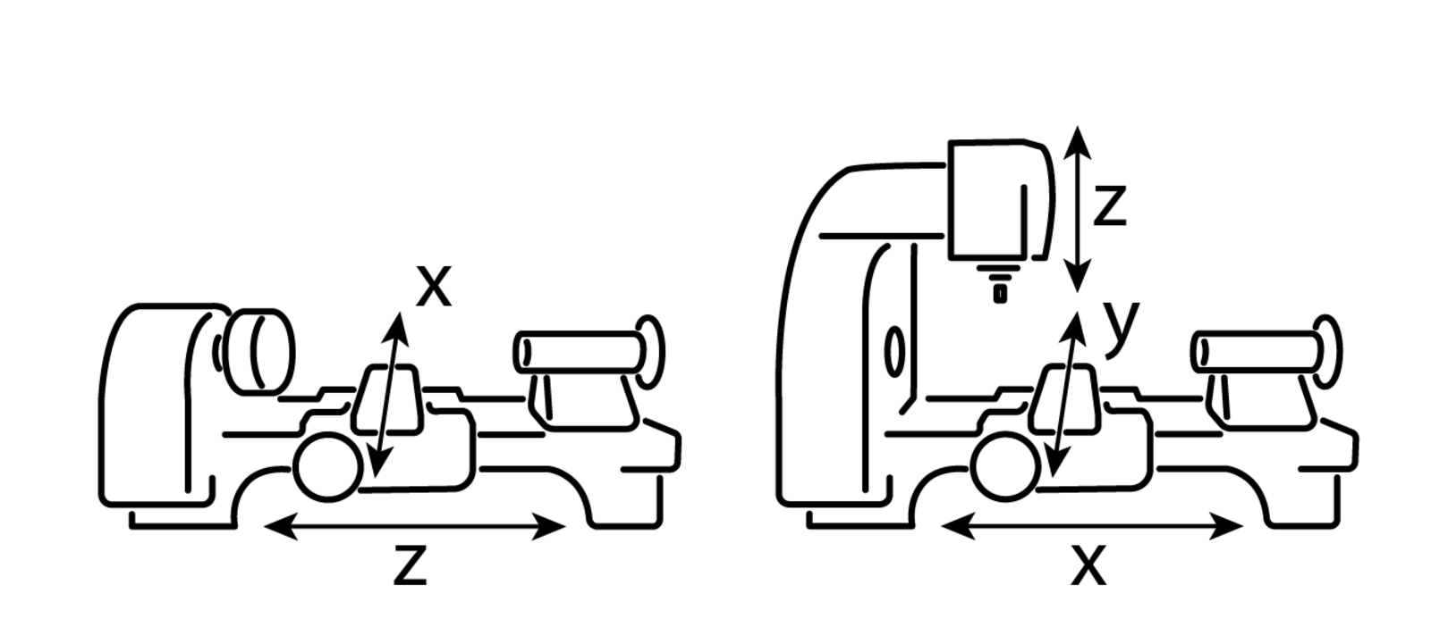
| Scale | Lathe mode | Mill mode |
|---|---|---|
| Longitudinal bed travel | Z | X |
| Cross travel | X | Y |
| Column or quill | Not used | Z |
The two profiles will take the "Lathe" and "Vertical Mill" machine types. That choice does more than label the profile. Lathe mode brings the lathe functions, including diameter and radius display on the cross slide and the lathe tool offset library, and mill mode brings the milling functions instead.
Universal Mills with a Vertical and a Horizontal Head
A universal mill has a horizontal spindle in the column and a vertical head that can be fitted over it. The spindles point ninety degrees apart, so the axis running parallel to the spindle changes when the head changes.
The table's long travel is unaffected. It is X in both modes, because it lies across both spindles either way. The other two swap. With the vertical head in use, the saddle travel is Y and the knee is Z. Switch to the horizontal spindle, and the saddle now travels along the spindle, which makes it Z; the knee becomes Y.
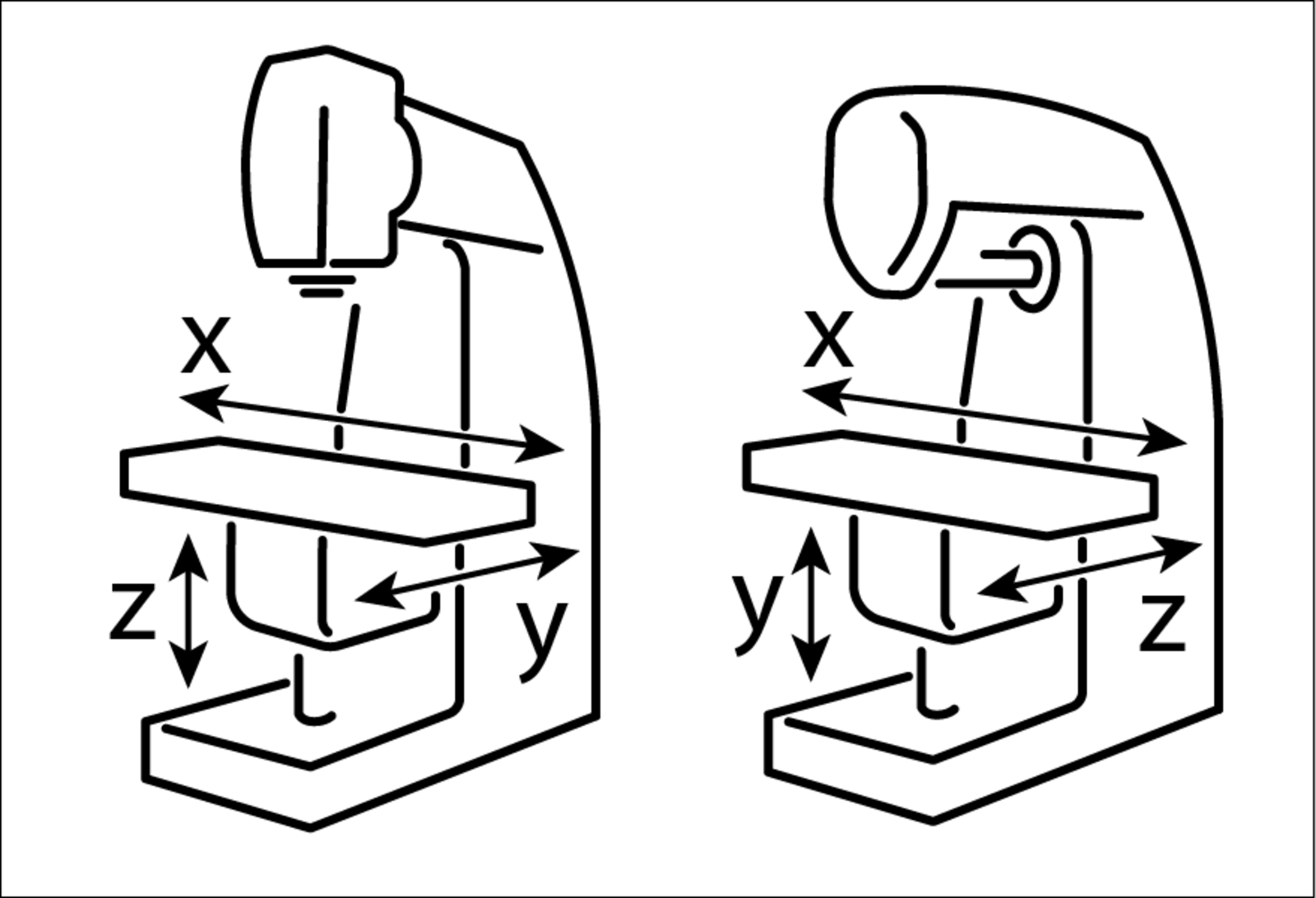
| Scale | Vertical mode | Horizontal mode |
|---|---|---|
| Table long travel | X | X |
| Saddle (in and out) | Y | Z |
| Knee (up and down) | Z | Y |
The two profiles will take the "Vertical Mill" and "Horizontal Mill" machine types.
Setting Up the Two Profiles
Set one mode up first and get it working, then build the second profile from it. Which mode comes first doesn't matter.
Set Up and Calibrate the First Mode
Configure the machine's first profile the way you would for a machine with one spindle, following the "TouchDRO Initial Configuration" guide, and calibrate the scales. Calibration is stored with the adapter rather than with the profile, so this is the only time it has to be done.
Create the Second Profile
Open the profile list by pressing the profile name at the top of the screen, and add a profile. Give it a name that says which mode it is for, and set the machine type to match that mode. Neither of those can be changed later. The axis settings the setup dialog offers are a starting point and will be adjusted in the next step, so they don't need to be right yet.
TouchDRO will switch to the new profile once it is created. Connect it to the same adapter the first profile uses.
Point Each Axis at the Right Input
This is the step that does the real work. Each axis reads a named input stream from the adapter, and the "Prefix" setting is what names it. Changing the prefix points a readout at a different scale, which is why no scale has to be unplugged or moved.
Open the settings for each axis in turn and set its "Prefix" under "Primary Input" to the stream carrying that mode's scale. On a universal mill, for instance, the knee scale keeps sending on the same stream in both modes; the vertical profile reads it as Z and the horizontal profile reads it as Y.
Enable Only the Axes the Mode Uses
Switch off any readout the mode has no use for, such as the vertical readout in lathe mode. An axis that is enabled but has nothing meaningful to report is a readout waiting to be misread.
Check the Direction of Travel
Move each axis and confirm the readout counts the way you expect. A scale that reads correctly as Y in one mode can read backwards as Z in the other, because the two modes look at the machine from different directions. The "Invert Readout" setting belongs to the axis in the profile you are in, so correcting it in the second profile won't disturb the first.
Switching Between Modes
Once both profiles are set up, changing modes takes one action on the tablet. Press the profile name at the top of the screen and pick the profile for the mode you are switching to. TouchDRO will load that profile's settings and reconnect to the adapter.
The switch is safe in the middle of a job. TouchDRO stores where you were with the profile you are leaving and puts it back when you return, so the mill setup will still be there after a spell in lathe mode.
What Each Profile Keeps to Itself
The two profiles are independent, and on a combination machine that cuts both ways.
The tool library is per profile, and tools are further separated by machine type, so lathe tooling and milling cutters won't appear in each other's lists. On a combination machine this is what you want, and it happens without any setting being changed.
Workspaces and sub-datums are per profile as well. A datum established in one mode doesn't carry over to the other, so a part that is machined in both modes will need its datum set again after the switch. The part itself may not have moved, but as far as each profile is concerned it is being measured in a different coordinate system.