
Reverse Engineering a Part with a Digital Microscope
Every once in a while you need to make a mating part or a holder for something that already exists. The part in the photo above is a flange from a hammer drill that we are converting into a custom tool, reusing the drill as a motor and gearbox donor. The mating part is the outer wall of the gearbox, so it needs a cover with holes positioned precisely over the gear axes.
Accurately measuring those hole centers the traditional way would take a set of machinist buttons and a good amount of patience. You fit a button to each hole, indicate it, write down the coordinate, and repeat. It works, and it has worked for a century, but it is slow and every transcription is a chance to introduce an error.
A toolmaker's microscope with a geometric readout makes this kind of job much quicker. You sight a few points on the edge of each feature through the crosshairs, and the readout calculates the center of the hole, its diameter, or the distance to the next one. Unfortunately, a setup like that costs thousands of dollars, so few home shops have one.
With TouchDRO, you can do the same job on your milling machine. The table and the DRO scales already make a precise XY stage, and an inexpensive digital microscope, the kind sold for inspecting coins and circuit boards, serves as the crosshairs. In measurement mode, TouchDRO calculates the hole centers, diameters, distances, and angles from the points you sight, and saves them as coordinates. Since you measure the part on the same machine that will cut its mate, every saved hole center is a position you can crank straight to, and you never need to copy a number by hand.
The "Recommended Microscopes and Cameras for Milling Machines" page covers the models we have tested and how to choose one. Let's use the flange to see the workflow start to finish. The steps are setting the origin, squaring the readouts to the part, measuring the holes and the outline, exporting the result as a drawing, and drilling the cover.
Before You Start
This guide assumes the microscope is already mounted on the mill and has a probe profile with its offsets captured. The "USB Centering Microscope Setup" guide covers that setup: the mount, the USB connection, and the offsets.
You can follow the workflow below whether you watch the image on the microscope's own screen or feed the video into TouchDRO. If you use the video feed, the "Live Camera Feed" page explains the on-screen side.
Clamp the part with the face you want to measure facing up. It doesn't need to be square to the table, since you can square the readouts to the part instead, as described below. The face should be level, though, so that the microscope stays in focus as you move across it.
Setting Up the Measurement
Before measuring any features, you need to tell TouchDRO three things: which instrument you are sighting with, where the part's origin is, and which way the part is turned.
Selecting the Microscope
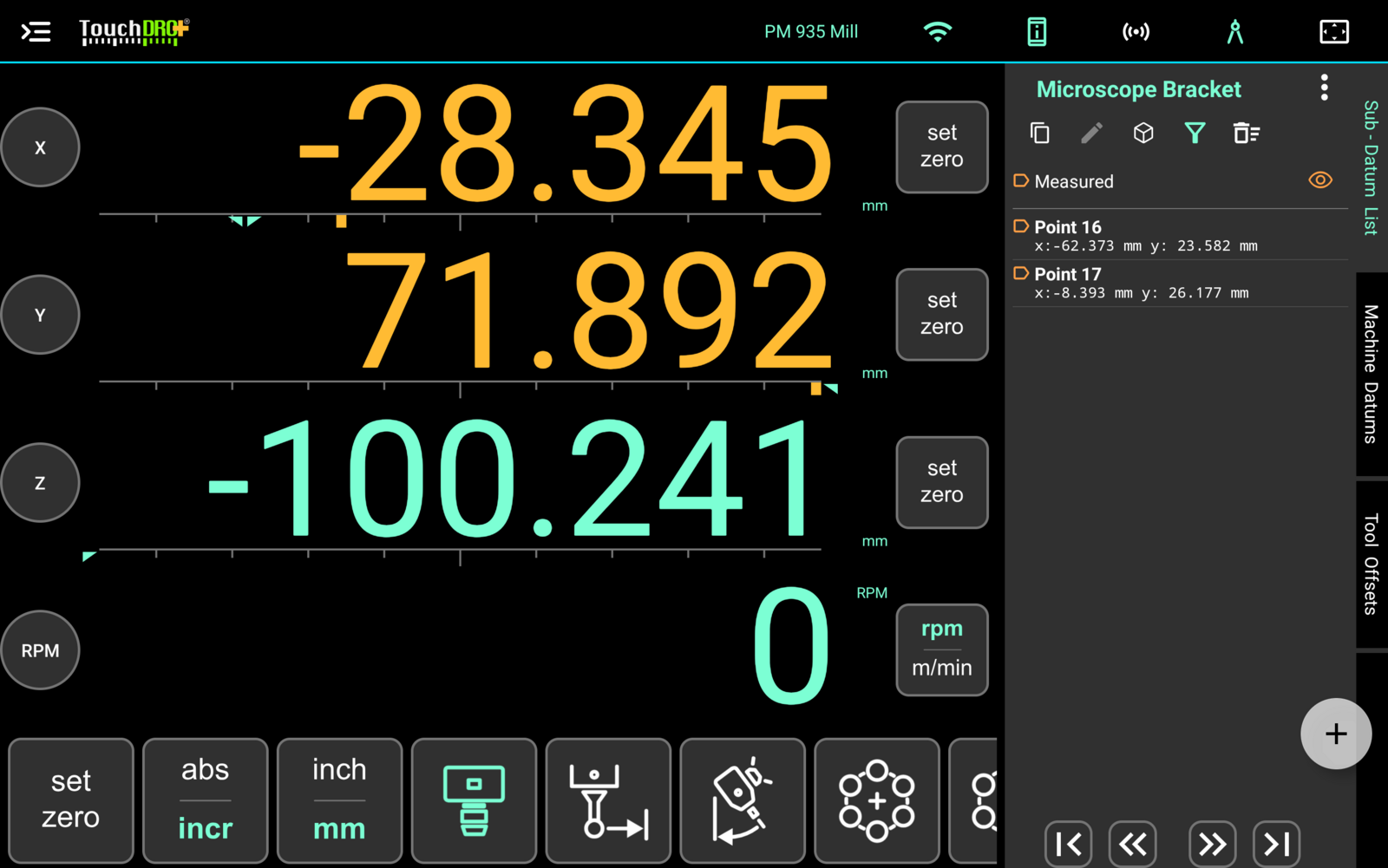
To start, switch TouchDRO into measurement mode by tapping the drafting compass button in the application header. Then tap the "Reference instrument" button in the function strip and choose the microscope's profile from the "Instrument" selector.
The microscope is mounted off to the side of the spindle, and its profile has the X and Y distance between the two. With the profile selected, TouchDRO applies those offsets to everything you capture. In other words, the saved coordinates will be correct in relation to the spindle when you switch back to cutting. The X and Y readouts are drawn in amber as a reminder that an offset is active.
Setting the Origin
TouchDRO states every coordinate you capture in relation to the absolute origin, so the next step is to set that origin on the part. Choose a feature that you will be able to locate again on the mating part. A corner where two straight edges meet works well, and so does a hole.
To set the origin, open the "Indicate Workpiece" function and select the microscope's profile in the "Probe" list. With a microscope, you indicate a feature by lining the crosshairs up with it. To take an edge, lay the matching crosshair line on it and tap the button for that edge. For a small hole or a punch mark that fits in the field of view, center the crosshairs on it and tap the center button. After that, press "Set Origin".
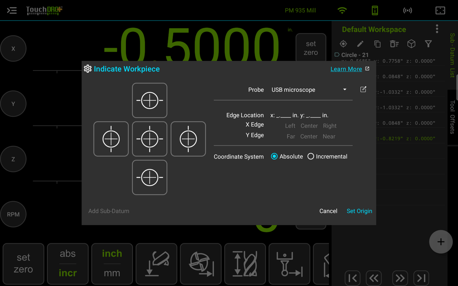
If the best reference is a bore that is too large to see whole, set the origin on anything convenient for now. Then measure that bore first, as described in the "Hole Centers and Diameters" section, save its center, and make it the origin with the "Align Absolute Origin to Sub-Datum" command before going any further.
Squaring the Readouts to the Part
A part that came off another machine rarely sits square in the vise, and indicating it in can take longer than measuring it. Using the "Align Measurement Axes" function, you can leave the part the way it sits and turn the X and Y readouts to match it instead. From then on, every coordinate you capture is stated in the part's own frame, which is what you want in the drawing.
Now that the origin is set, open the "Align Measurement Axes" dialog and choose "Measured" in the "Angle source" row. Move the crosshairs to one end of the edge you want to measure from and set "Point A" with "Current". Then move to the other end of the edge and do the same for "Point B". TouchDRO will fill in "Angle (α)" from the two points. Tap "Align" to apply it.
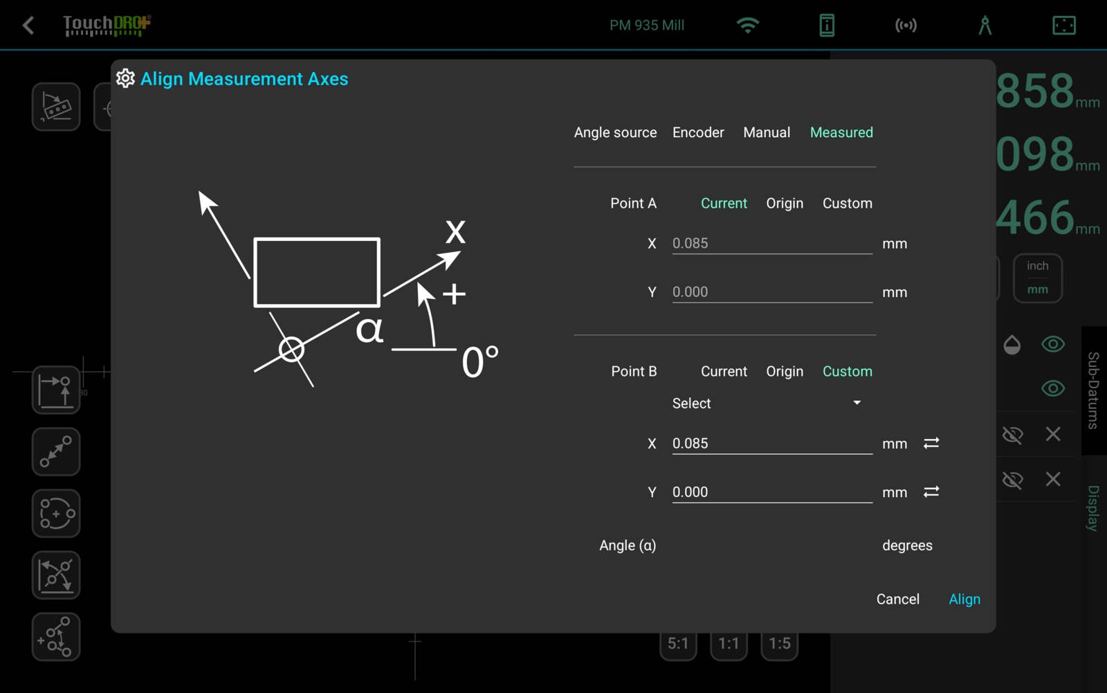
Spread the two points as far apart as the part allows, since the error in the angle is roughly the error in a point divided by the distance between them. If the part has no straight edge, you can use two small holes instead: center the crosshairs on the first hole for "Point A" and on the second one for "Point B".
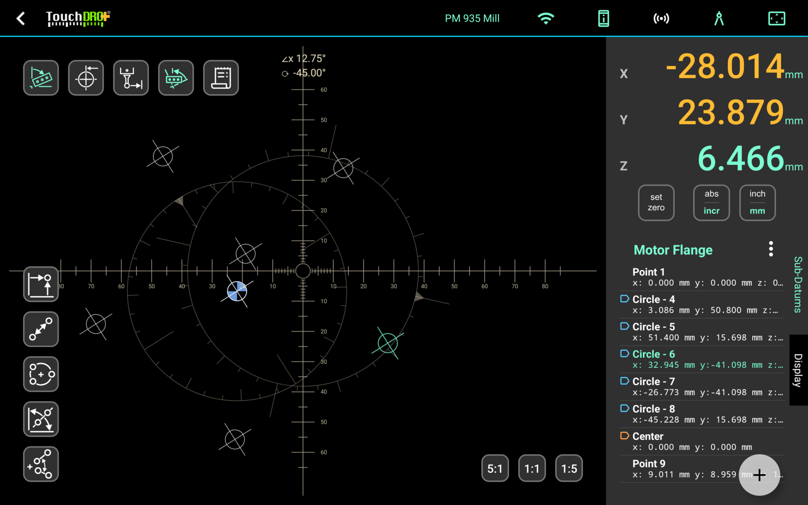
With the angle applied, the X and Y readouts are drawn in amber, and TouchDRO shows the angle and a protractor ring in the graphical view. To check the result, move along the edge you squared to: X should count while Y stays put.
Measuring the Part
With the setup done, switch to the graphical view. The measuring functions run down its left edge. To use one, tap it, and TouchDRO will open a card with a slot for each point the function needs. To capture a point with a microscope, line the feature up under the crosshairs and tap the lit slot. The card will show the result as soon as it has enough points.
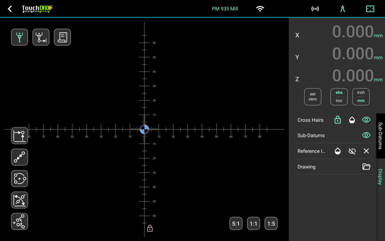
The "Measurement Functions" page describes every function and the card in detail. This guide only covers what a part like our flange needs.
Hole Centers and Diameters
When measuring a hole, you need to know where its center is, and there is nothing at the center to put the crosshairs on. On a small hole, you can judge the middle by eye, but on a bore that is wider than the microscope's field of view, you only ever see a short piece of its edge. Using "Circle from Points", you can find the center from the edge instead.
To measure a bore, tap "Circle from Points", move the table until the crosshairs sit on the edge of the bore, and tap the lit slot. Do the same at two more places around the bore. TouchDRO will fit a circle through the three points, draw it in the graphical view, and show its center and diameter on the card. Spread the points around the bore as evenly as you can. Three points bunched on one side still define a circle, but a small error in any of them moves the center a long way.
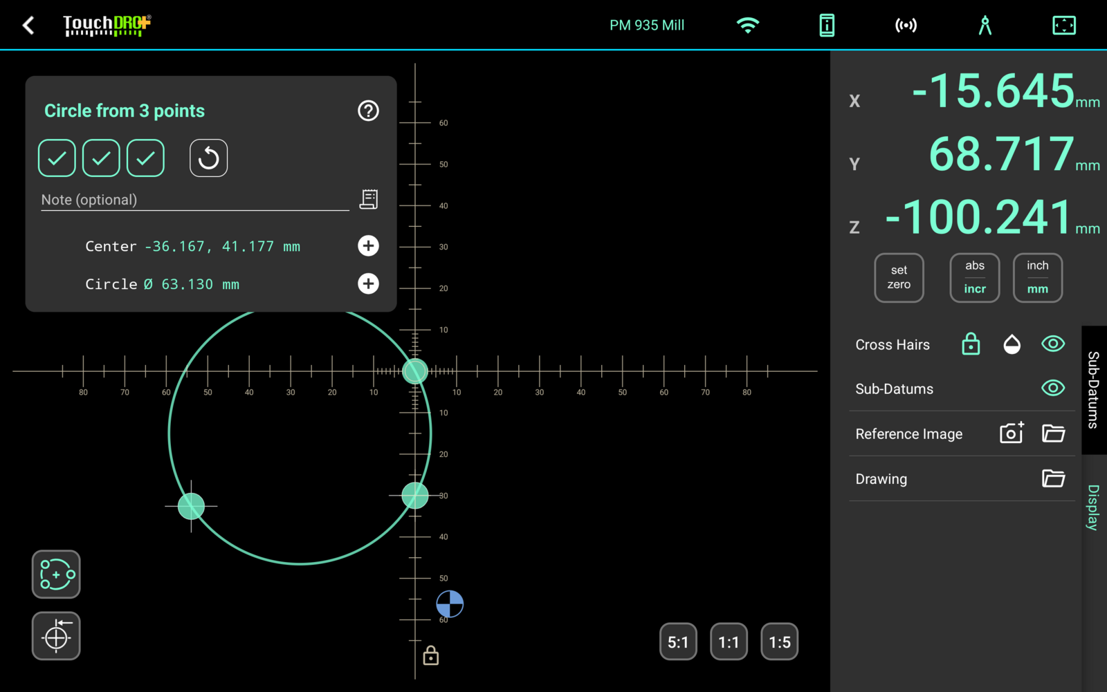
Three points define a circle exactly, so with only three you can't tell whether one of them was off. If you keep capturing after the third point, TouchDRO will fit the circle that agrees best with all of the points. With four points or more, the card also shows how far the points are from the fitted circle, which on a worn bore tells you how much to trust the diameter. From five points on, TouchDRO draws a point that sits clearly off the circle in amber, and you can long-press it to remove it.
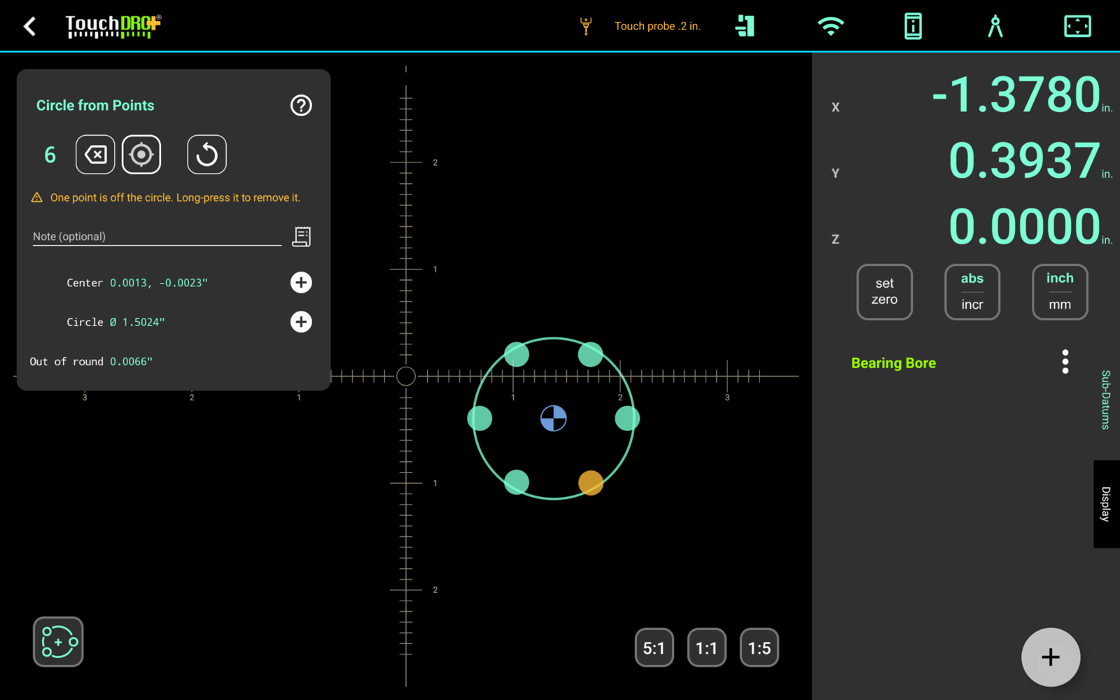
Once the card shows the result, tap the "⊕" beside the center to save it as a sub-datum, and the "⊕" beside the diameter to add the circle to the drawing. It's a good idea to rename the point in the sub-datum list right away, while you still remember which hole it was. Then move on to the next hole, until you have saved every hole in the pattern.
Using a microscope, you can see what you are aiming at, which is an advantage over a touch probe in this kind of work. A probe triggers on whatever is proud, such as a burr or a dinged edge, while under magnification you can put the crosshairs on the edge that actually defines the hole. On a chamfered hole, focus past the chamfer, on the edge where the bore itself starts.
Hole Spacing and Bolt Circles
After the centers are saved, you can measure between them without going back to the part. While a function is active, tap a saved point in the graphical view, and TouchDRO will take it as the next point.
For example, tap "Point-to-Point Distance" and then the centers of two bores. The card will show the straight-line distance between them, along with ΔX, ΔY, and the midpoint. For two gear shafts, that center distance is the dimension the cover has to reproduce most closely.
You can get a bolt circle the same way. Tap "Circle from Points" and then the saved centers of three screw holes, and TouchDRO will show you the diameter of the bolt circle and its center.
Slots, Edges, and Corners
You can measure slots, edges, and corners the same way, with two points on each edge.
To measure the width of a slot or the distance between two parallel faces, use "Distance Between Lines". Capture two points on the first edge and two on the second. The card will show the distance, the angle between the edges, and the midpoint, which you can save as a sub-datum to mark the center of the slot.
To find a corner that is rounded over or damaged, use "Angle Between Lines" with two points on each of the edges that lead into it. Along with the angle, TouchDRO calculates the point where the two edges would meet, and you can save that point even though you never touched the corner.
For a single edge, "Line Angle" shows you how far it runs off square, from two points along it. For all three functions, spread the two points on an edge as far apart as you can.
Tracing the Outline
To make a cover that matches the flange, you also need the shape of the flange itself. Using "Outline from Points", you can trace it. Tap the function, put the crosshairs on the edge of the part, and tap the capture button. Then work your way around the part, capturing a point at each place where the edge changes direction. TouchDRO draws the outline through the points in the order you took them.
Most parts have both straight edges and curves, and it's best to trace them in pieces. Take the straight sides as one outline, with a point at each corner. Then take each curve as its own outline that starts and ends on points you already saved. For a curve that is part of a circle, switch on "Smooth the outline with arcs". For a free-form curve, use the spline switch instead. When a piece looks right, tap the "⊕" on the "Outline" row to add it to the drawing, and the "⊕" on the "Points" row to save its points as sub-datums.
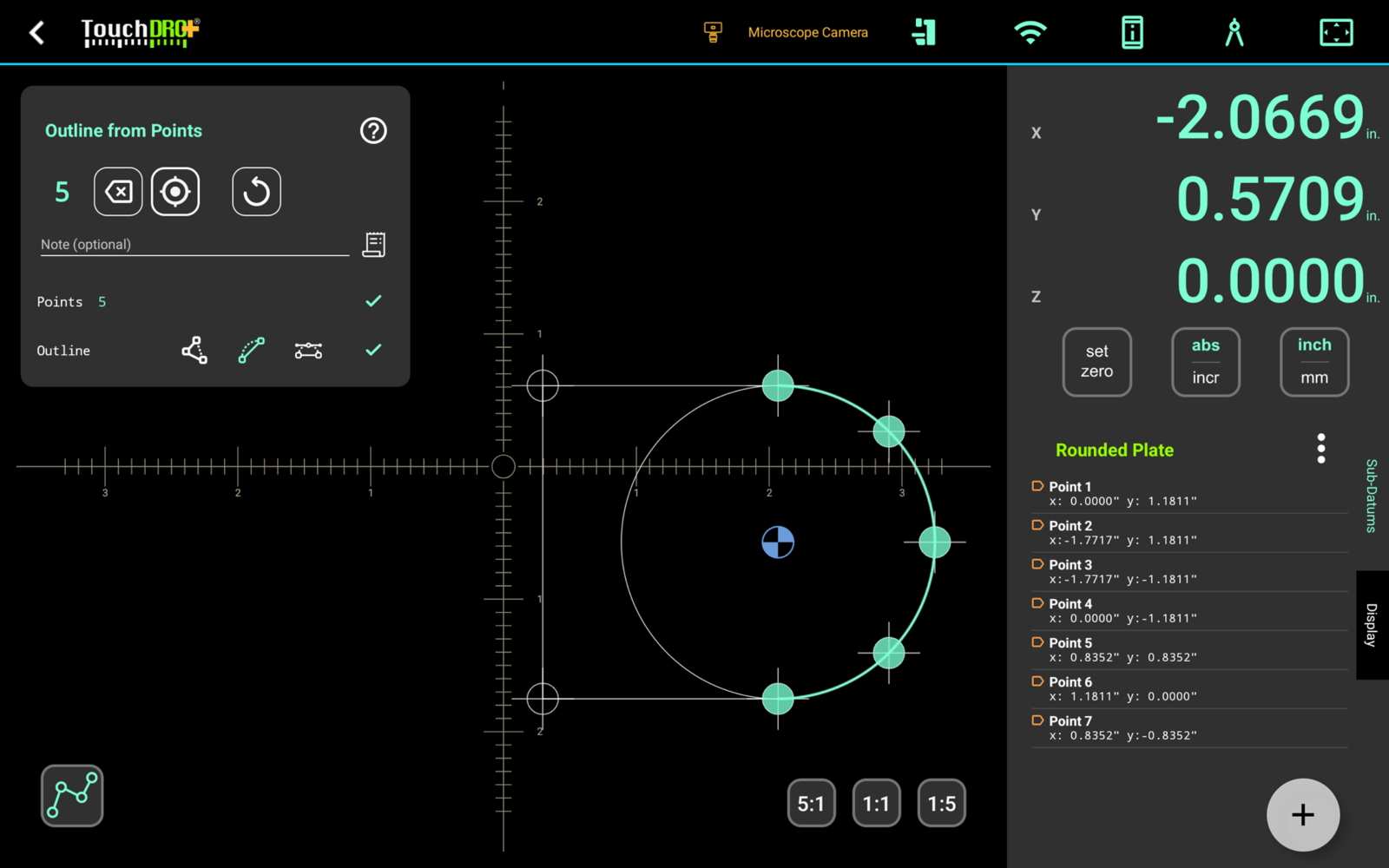
The "Digitizing a Complex Outline" section of the "Measurement Functions" page walks through a plate with a rounded end, and shows what the two kinds of smoothing do to the same points.
Logging the Measurements
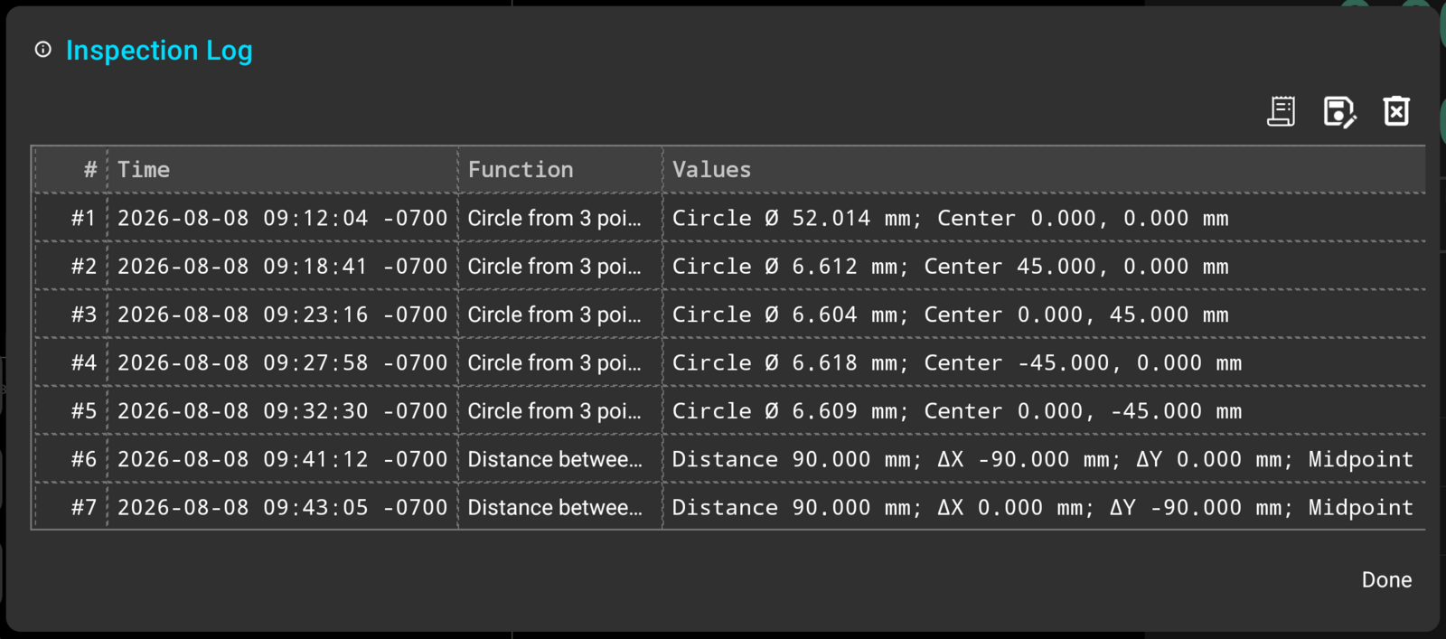
When you save a result, TouchDRO stores a coordinate. To keep the measured values as well, such as a diameter or a center distance, type a note into the field on the card and tap the log button beside it. TouchDRO will add the measurement to the inspection log, with the points behind it and your note.
The log is kept with the workspace. You can open it from the graphical view while no function is active, and export it as a text file or as a CSV file for a spreadsheet.
Taking the Measurements into CAD
At this point, the workspace has every hole center as a sub-datum, and the drawing has the fitted circles and the outline. For a simple cover, that is all you need, and you can skip to the next section. If the mating part needs features of its own, you can export the measurements and finish the design in your CAD package.
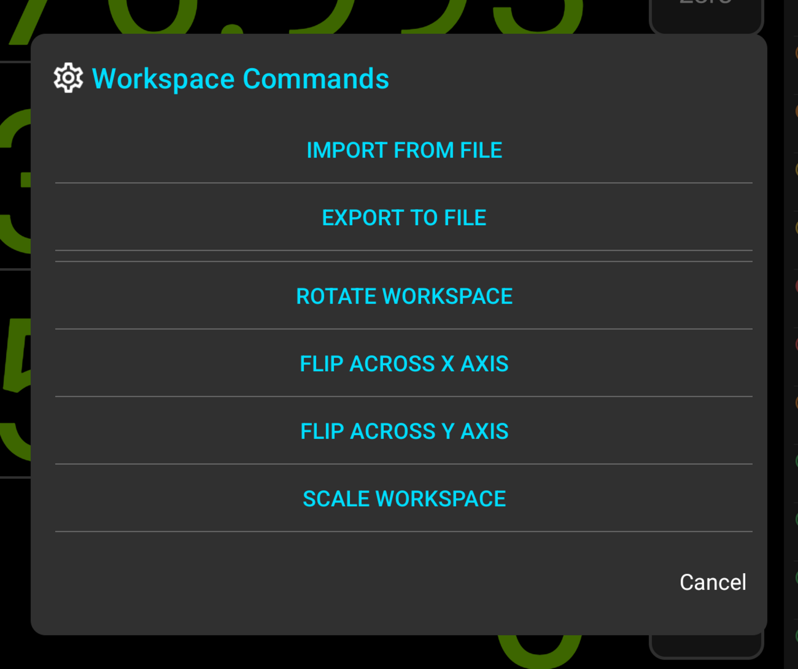
To export the drawing, open the "Workspace Commands" menu with the menu ("⋮") button in the upper-right corner of the sub-datum panel, and tap "Export to DXF File". TouchDRO writes the whole workspace at 1:1, with the sub-datums as points you can snap to and the measured circles and outlines on a layer named "MEASURED". The origin of the file is the origin you set on the part, so anything you draw over the top lines up with the part you measured. You can find the layer names and the units of the file in the "Exporting a Workspace to DXF" guide.
Note that the DXF file has the geometry, but the diameters, distances, and angles you measured are not in it. Those are in the inspection log, which is one more reason to log each measurement as you go.
Once the design is done, the "Machining to a CAD Drawing" guide covers bringing the drawing back to the mill.
Machining the Mating Part
Because you measured the flange on the mill, every saved hole is already a position you can crank back to. To drill a simple cover, you only need to line the workspace up with the new blank.
To start, clear the angle with "Clear" in the "Align Measurement Axes" dialog, so that the readouts follow the machine's axes again. Then tap the drafting compass button to leave measurement mode, and TouchDRO will switch the readouts back from the microscope to the spindle.
After that, take the flange off the table and clamp the cover blank square. If you measured from a corner of the flange, indicate the matching corner of the blank and set the absolute origin there. If you measured from a hole, position the spindle where one of the holes should be on the blank, long-press that hole's point in the graphical view, and choose "Align Sub-Datum to Spindle". TouchDRO will move the whole workspace so that the point is under the spindle, and the rest of the pattern will follow it.
Before drilling, think about which face of the cover is up. The flange was measured looking at its mating face. If you drill the cover with its outside face up, the pattern is the same as you measured it. If you drill it with the mating face up, the pattern is mirrored, and you will need to flip the workspace first with "Flip Across X Axis" or "Flip Across Y Axis" in the "Workspace Commands" menu.
Now tap the first hole in the sub-datum list. TouchDRO will make it a temporary zero, so the readouts show the distance left to travel. Crank both axes to zero, spot-drill, and tap the next hole. Once every hole is spotted, lay the cover against the flange and check that the spots line up with the holes before you drill through.
To cut the outline, apply an end mill in the "Tool Compensation" dialog and mill to the measured outline on the screen, the same way the "Machining to a CAD Drawing" guide mills to the lines of an imported drawing.
What a Microscope Can't Measure
With a microscope, you can only measure what you can see, in one plane. You need a clear line of sight and decent lighting, and glare from a shiny surface can make an edge hard to judge. You can't reach into a bore with it to measure below a chamfer or a step, and it doesn't measure depths or heights. For those, you still need a caliper or a depth micrometer.
For walls you can't see, a touch probe is the better instrument. You can use every measuring function except "Outline from Points" with a probe, and TouchDRO corrects for the tip in the functions that fit a line or a circle. The "Flagged Points" section of the "Measurement Functions" page explains where it can't.
How accurate the result is depends on your scales, on how well the microscope is aligned with the Z travel, and on how consistently you can place the crosshairs on an edge. To find out what your own setup does, measure something you know the size of, such as a ring gauge or a 1-2-3 block, the same way you measured the part, and compare the numbers. If a part needs a traceable inspection report, it has to go to a metrology lab.
This guide only used the functions the flange needed. The full reference is the "Measurement Functions" page, and the "Align Measurement Axes" page covers squaring the readouts in more detail. If the mating part only needs clearance holes, the "Machining a Part from a Photo" guide covers a quicker way to get them, working from a photo of the part.