DIY DRO Adapter Kit for iGaging and Shahe Scales
TouchDRO DIY Wireless DRO Kit (Unassembled) for 3V iGaging EZ-View DRO Scales, iGaging Absolute DRO Plus Scales, and Shahe Digital Liner DRO Scales. The adapter supports: four DRO scale inputs, tachometer input, and touch probe/tool height setter input. The kit contains the PCB and all of the parts needed to build a TouchDRO adapter board.
TouchDRO DIY Adapter Kit for iGaging and Shahe scales provides the functionality and features identical to the pre-assembled TouchDRO Adapter for iGaging or Shahe scales but comes with much lower price. It supports the following scales:
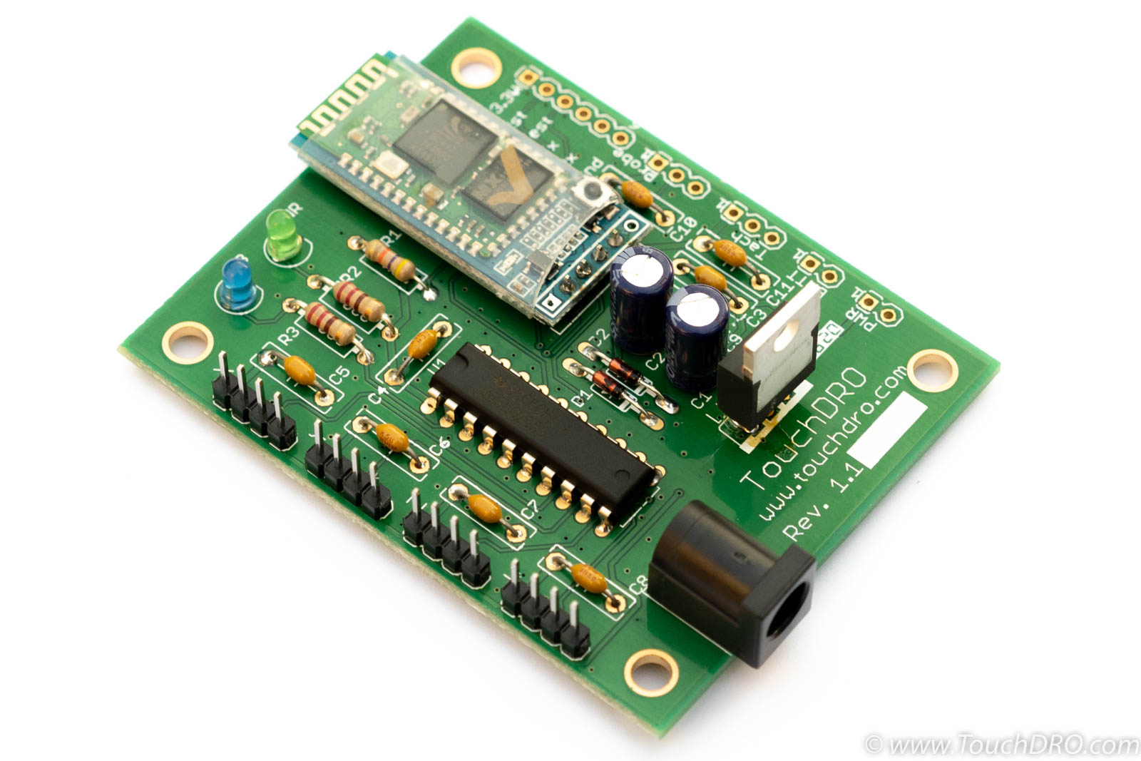
The kit comes pre-flashed with the same firmware version as the assembled TouchDRO Adapters and is designed to be easy to build by someone with only basic soldering skills. The circuit board is carefully laid out to ensure maximum resistance to electromagnetic interference and noise to ensure reliable DRO functionality.
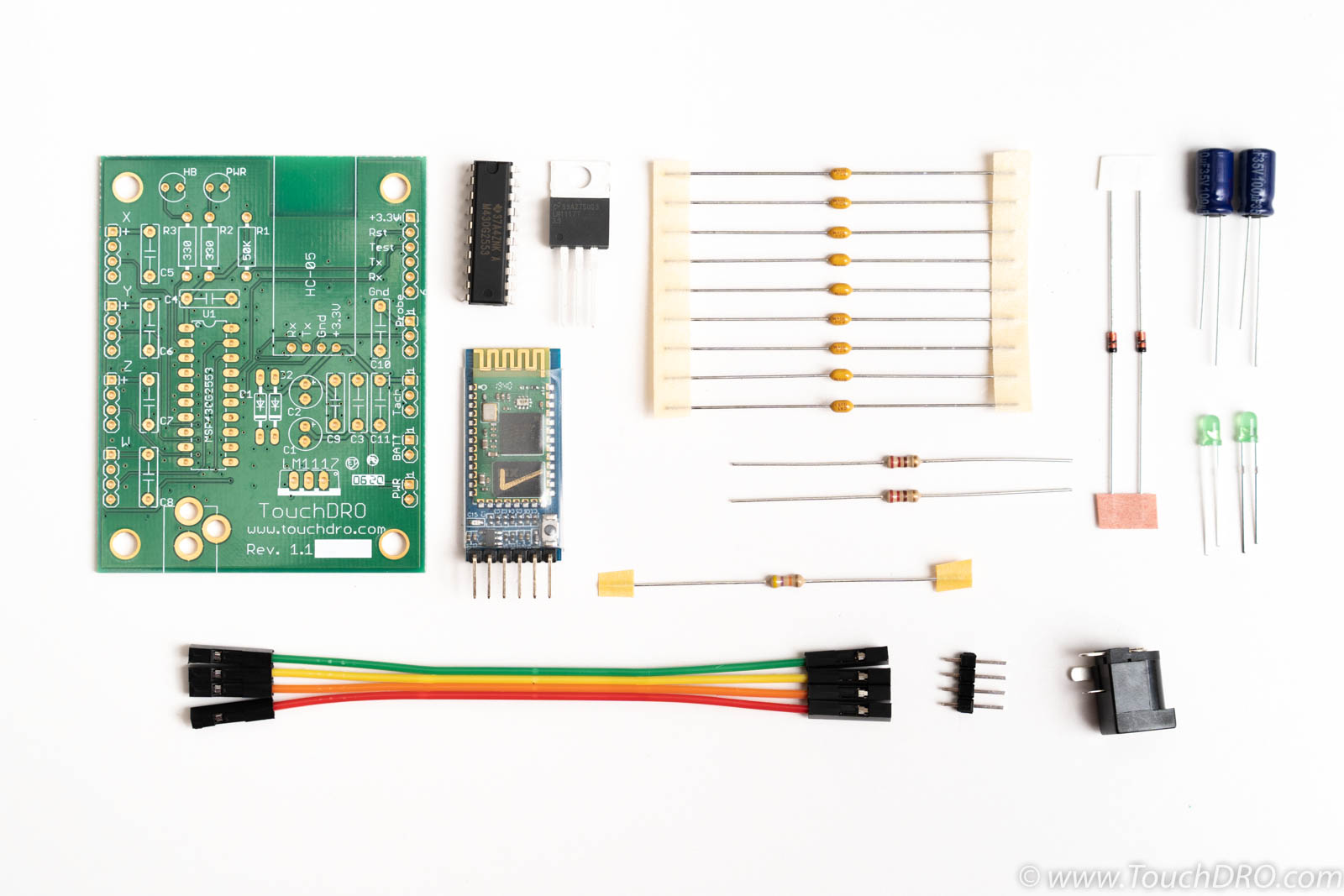
The kit includes the following components:
- Bare printed circuit board built to IPC-A-600 Class II quality standard
- MSP430 microcontroller, preprogrammed with TouchDRO firmware
- HC-05 Bluetooth transceiver
- Texas Instruments low dropout voltage regulator
- Durable Panasonic electrolytic capacitors
- Set of name brand resistors, ceramic capacitors, and LEDs
- Power supply jack, 4-pin headed, and 4-conductor ribbon cable
To complete a DIY DRO setup you will need to provide a set of compatible linear scales, 5V-9V power supply, and a suitable enclosure.
Supported Scales
DIY DRO adapter kit supports 3V capacitive linear scales that use iGaging 21-bit protocol, iGaging Absolute protocol and BIN6 protocol. This inludes:
- iGaging EZ-View DRO Plus
- iGaging DigiMag (and it's rebranded variants)
- iGaging Absolute DRO Plus
- Shahe 5403-xxx "Digital Liner DRO Scales with Round Display"
- Shahe 5403-xxxA/F "Digital Liner DRO Scales with Square Display"
If your scale displays look like one of the displays below (including color and markings), this adapter will work with them

Each circuit board is fully electrically tested by the manufacturer. Additionally, I personally program and test every microcontroller, inspect each PCB, and check the kit before shipping it out.
Specifications
Features
- Supports four linear axis inputs, tachometer, and touch probe or tool setter input
- The on-board linear voltage regulator provides a clean power supply to the scales
- Per-scale bypass capacitors filter out spikes on the power supply lines
- Provisions for a separate scale power supply from a battery pack for added reliability
| Scale Inputs | 4 |
|---|---|
| Tachometer Input | Yes |
| Probe/Height Setter | Yes |
| Power Supply | 5V DC - 9V DC |
| Current Draw | Approx. 50 mA |
| Width | 2.325" |
| Length | 2.9" |
Mechanical Drawings

Kit Contents
This DIY DRO kit includes all of the components needed to assemble a TouchDRO adapter.
| Value | Description | Qty. | Reference |
|---|---|---|---|
| PCB | TouchDRO Adapter PCB, Immersion Gold plated, Green solder mask, White silkscreen | 1 | N/A |
| MSP430G2553 | 16-Bit mixed-signal microcontroller (pre-programmed) | 1 | U1 |
| HC-05 | Bluetooth Transceiver, Slave | 1 | HC-05 |
| LM1117T-3.3 | Voltage Regulator, 3.3V 800 mA, LDO | 1 | LM1117 |
| Capacitor, 100 uF | Cap. electrolytic, 110uF, 35V | 2 | C1, C2 |
| Capacitor, 0.1uF | Cap. ceramic, 0.1uF 50V | 9 | C3-C11 |
| Resistor, 330 Ohm | Metal film resistor, 330 Ohm, 1/4W, 5% | 2 | R2, R3 |
| Resistor 47KOhm | Metal film resistor, 47 KOhm, 1/4W, 5% | 1 | R1 |
| Diode | Schottky Diode, 20 mA 40 Volt | 2 | D1, D2 |
| LED | LED, Green 3mm, 20 mA | 2 | HB, PWR |
| Power Jack | 2.1x5.5 mm power input jack, PCB mount | 1 | Pwr |
Documentation & Resources
Useful Resources
Port Functions
Important Note
Inputs on the board are unbuffered. I.e. they are connected directly to the GPIO (General Purpose Input/Output) pins of the MSP430 microcontroller. In order to work correctly, the microcontroller expects a "Low" signal of less than 0.65V and a "High" signal level of around 3V (3.3V nominal). A signal level above 3.6V can permanently damage the microcontroller. Conversely, a signal with a level below 2.25V will not trigger input interrupts reliably.

Axis Inputs
TouchDRO DIY Wireless DRO kit supports up to four capacitive axis inputs. During the power-up sequence, the microcontroller automatically detects scale protocol and configures the internal pull-up/down resistors to suit the scale's requirements. If no signal is detected on an input, the firmware will disable it until the next reboot.
Tachometer
The board supports non-directional tachometer input with a frequency range of 1Hz to 10KHz. The tachometer input pin is pulled down to the ground via an internal resistor; the tachometer should provide a sourcing output (either PNP or push/pull)
Touch Probe
Touch probe input is a binary on/off input. The pin is pulled down to the ground via an internal resistor. The firmware can handle either a normally-open or normally-closed probe. During boot time, it detects the state of the input and assumes that the probe is in "Off" state; the opposite state will be treated as "On".
Power Input
The board uses a center-positive 5.5mm x 2.1mm power input jack. The on-board voltage regulator can use supply voltage ranging from about 3.6V DC to 12V DC and can work with a range of power supplies. For best results, a power supply should provide at least 200 mA of current and 5V to 9V.
A 2-pin "Pwr." header is wired in parallel with the power jack. It provides an option to use a panel-mounted power jack with an inline On/Off switch.
Battery
This DIY DRO kit is designed to accept an external battery pack to power the scales, either continuously or as a backup during a power failure (please see "DIY DRO Kit Build Instructions" for more details on how to build the board to use a particular configuration).
Scale power is connected to the battery pack and/or the main voltage regulator through a Schottky diode. During the normal operating conditions, the diode has a forward dropout voltage of less than 0.3V. Therefore, the battery pack should provide a voltage between 3V and 3.3V. For best results use a pair of non-rechargeable AA or larger batteries.
Grounding
Proper grounding is very important for a stable operation of your DIY DRO setup. Capacitive DRO scales are inherently very sensitive to EMF and power supply fluctuations. The easiest way to reduce EMF issues is to ground the board to the machine's frame and ensure that the scales' cables are connected to the ground only on one side. Mounting holes on the board are tied to the ground fill, as are all of the ground pins. For more details please refer to the "Avoiding Common DRO Scale Problems" page.