Wireless DIY DRO Adapter for iGaging Scales
TouchDRO adapter for iGaging linear DRO scales supports iGaging EZ-View DRO Plus, iGaging DigiMag Remote DRO and iGaging Absolute DRO Plus scales with Micro-USB cables. Older iGaging scales and the new Shahe Remote Digital DRO Display scales can be connected by using appropriate breakout boards. The circuit is specifically designed to achieve excellent stability, reliability, and noise resistance with capacitive DRO scales.
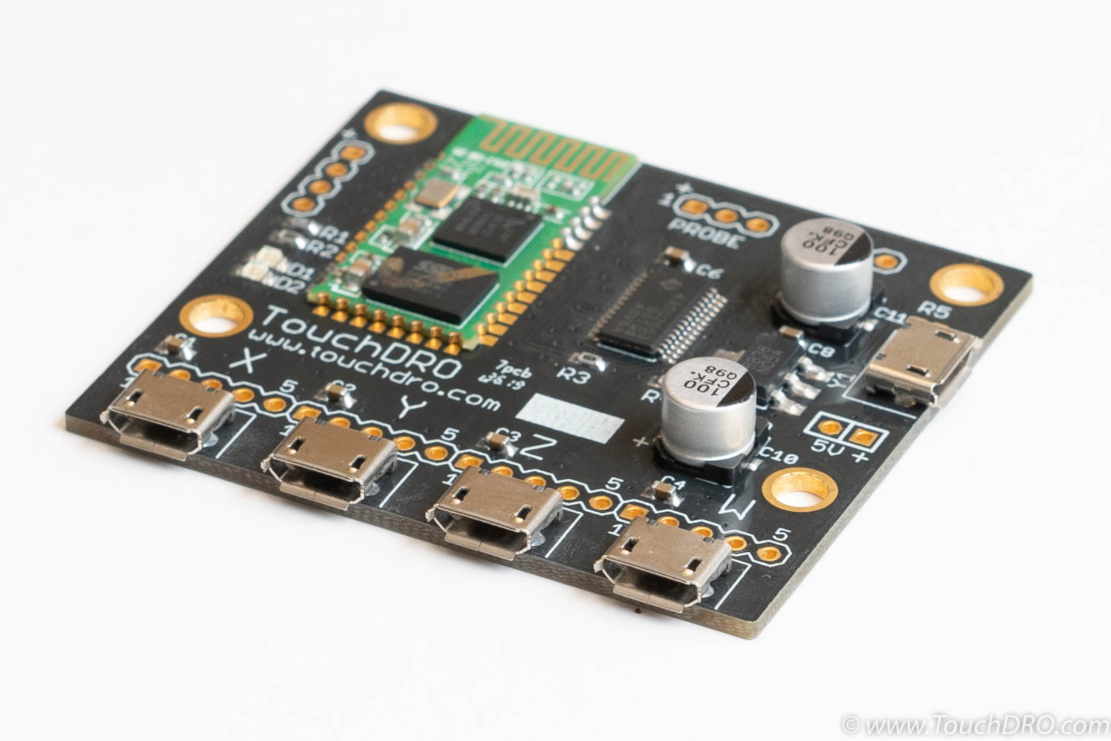
Designed from the ground up to provide the best performance and reliability, this is the most popular TouchDRO BlueTooth adapter. It is compatible with the classic iGaging DigiMag Remote DRO, AccuRemote, iGaging Absolute DRO+, iGaging EZ-View, and other 21-bit scales. In addition to four linear scale inputs, the controller supports a tachometer and a touch probe/height setter input.
This adapter was available as a bare board or as a kit with a custom 3D-printed enclosure. The kit included the fully assembled and tested adapter board, a two-color 3D printed enclosure, and the necessary mounting hardware.

Supported Scales
This DRO adapter firmware supports capacitive linear scales that use iGaging 21-bit protocol, iGaging Absolute protocol and BIN6 protocol. This inludes:
- iGaging EZ-View DRO Plus
- iGaging DigiMag (and it's rebranded variants)
- iGaging Absolute DRO Plus
If your scale displays look like the ones of the displays below (including color and markings), this adapter will work with them.

Note, older versions of the scales pictured above used Mini-USB cables. With the exception of the Absolute DRO Plus scales, Mini-USB scales can be connected ot this adapter by using straight Mini-USB Female to Micro-USB Male adapter cables. Older iGaging Absolute DRO Plus scales used a different pinout and need to be used with custom-wired Mini-USB breakout boards. Refer to the "Connecting the Scales" section below for connection details.
 and Mini-USB (right) connectors")
All genuine TouchDRO adapters are fabricated and assembled to stringent IPS-A-600/610 Class II or better standard and use quality name brand components for best reliability and durability. I personally inspect and program every board and run it through a full range of tests (scale connectivity, bluetooth, etc.) right before shipping it to you.
Specifications
Features
| Scale Inputs | 4 |
|---|---|
| Tachometer Input | Yes |
| Probe/Height Setter | Yes |
| Power Supply | 5V DC |
| Current Draw | Approx. 30 mA |
| Width | 1.9" |
| Length | 2.1" |
Mechanical Drawings

Documentation & Resources
Port Functions

| Port | Description |
|---|---|
| X,Y,Z,W Inputs | Inputs for four linear axes. |
| Tach | Tachometer input (unbuffered). Tachomter requires optical encoder with quadrature output |
| Probe (unbuffered) | Tool height setter/touch probe input |
| Power | Micro-USB Power supply input, 5V DC nominal. |
Scale Inputs
This DRO adapter board comes with pre-installed USB Micro-B female connectors. Next to each connector there is a set of holes for a 5-pin 0.1" header that break out Vcc, Ground, Clock and Data lines for the axis.
Tachometer
The board is setup to accept a tachometer that has either push-pull or line driver quadrature output.
Touch Probe
Inexpensive touch probes and tool height setters work similar to a simple electrical switch. Depending on the configuration, when the probe touches the workpiece, it either opens the circuit or closes it (normally-closed or normally-open, respectively). TouchDRO board supports (and automatically detects) both types.
The probe can be connected as follows: connect one side of the switch to Vcc and the other to the probe pin. If the probe has a LED, it has to be reverse-biased (backwards), or the input won't work. To test this, connect the probe to Vcc and Ground. If the LED lights up (either when the probe is touching or not touching), reverse the leads.
Power Supply
This DRO adapter is designed to be powered by a common Micro-USB power supply such as phone charger. Alternatively, +5V and Ground pins are broken out next to the Micro-USB connector to allow the use of a panel-mounted power supply jack instead.
Status LEDs
DRO scale adapter has two status LEDs:
- Green - Heartbeat/status
- Blue - BlueTooth
When the board powers up, the green LED will blink rapidly for 2 seconds indicating that the protocol detection is in progress. During protocol detection, DRO will not read the position. After two seconds, it will start blinking once-per-second indicating normal operation.
The blue LED is used to indicate the connection status. It can be in one of three modes:
- When the board is not paired, the LED will blink twice per second.
- Once paired, the blinking pattern will change to one brief pulse every 2 seconds.
- When the board is connected to the application, the LED will switch to two brief pulses every 2 seconds.
Connecting the Scales
- iGaging EZ-View DRO Plus, DigiMag "Remote DRO Display" and Absolute DRO Plus scales that come with Micro-USB cables can be plugged directly into the pre-installed USB Micro-B connectors
- iGaging DigiMag "Remote DRO Display" scales (and their rebranded versions such as Shars Digital Machine Scales and AccuRemote DRO scales) with Mini-UBS connectors can be connected using a straight USB Mini-to-Micro adapter
- iGaging Absolute DRO Plus and Shahe 5403-xxxA Linear Scales with Remote Square Display can be connected using a set of USB Mini-B breakout boards
- iGaging Absolute DRO Plus and Shahe 5403-xxxA Linear Scales with Remote Round Display require custom connector or a direct connection
- Disconnect the power supply
- Plug-in the scales
- Re-connect the power
Grounding
Proper grounding is vital to relaible funciton of iGaging DRO scales. Unreliable ground connection or ground loop can lead to such issues as drifting positon or random resets. In order to avoid ground loops, there should be a single reliable connection to the machine chassis. Ideally, scale frames should be isolated from the machine. If the cables are shielded, the shields should be tied to the ground only on one side, and as close to the central grounding point as possible.
The board provides a number of easily accessible grounding poins. Each port has a dedicate ground pint that is tied to the common ground pour. There are two ground pins next to each Micro-USB port and finally, the mounting holes are tied to the common ground as well.
3D Printed Enclosure Assembly
The adapter was also available as a kit with a custom two-color 3D printed enclosure. The kit contents were as follows:
- TouchDRO Adapter board for iGaging Scales
- Two-color 3D printed enclosure
- 4x M3 16mm stainless steel screw
- 4x M3 stainless steel nut

The required assembly is very minimal and consists of inserting the board into the enclosure and fastening four screws.
Flip the bottom [black] part of the enclosure and press in the M3 nuts into the recesses so the result looks similar to the photo below.

Place the board into the enclosure with components facing up and scale inputs aligned with the corresponding openings. The fit should be pretty close, so it is best to start at an angle and push the protruding part of the USB sockets into the corresponding opening in the enclosure, as shown in the picture. Then lower the board into its position and gently press on the back of the USB socket until the edge of the board is against the inner enclosure wall. The power input connector should now be aligned with its opening and the mounting holes will be concentric with the holes in the enclosure.

Before closing the lid, plug in the scales, power up the board, and pair it with your device to ensure that the setup works as expected.
Info about the status LEDs and connecting the scales is farther up this page.
Place the lid as shown in the photo below and ensure that the screw holes light number with the mounting holes and the holes in the enclosure bottom. Insert and lightly tighten the four M3 screws. Check the lid for alignment and, if everything looks good, fully tighten the screws.
