Tips For Building a Reliable DIY DRO Circuit
For someone with limited soldering experience and knowledge of electronics building a DIY DRO can be daunting. Fortunately, TouchDRO scale adapters have relatively simple circuits and large through-hole components; and following the tips and guidelines described on this page will help you build a solid and reliable DIY DRO.
Tools and Materials
Soldering requires some basic tools and materials. As a bare minimum it would be a soldering iron, suitable solder, and some means of cutting the leads and/or wires; the rest of the items in this list are by no means necessary.
Soldering Iron
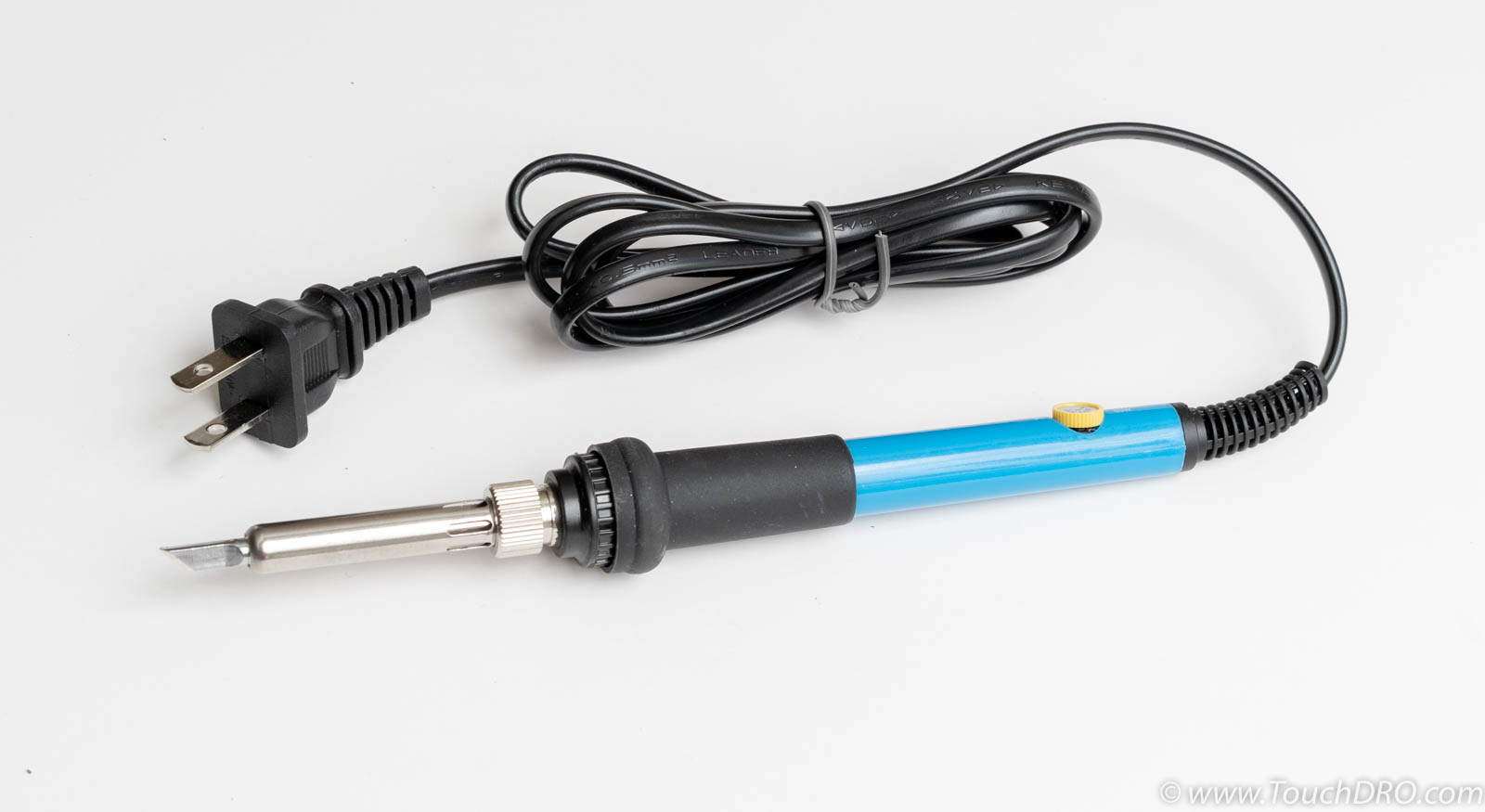
For casual DIY soldering a basic soldering iron in 60-80W range will be good enough and can be purchased for under $20. It's best to find a model that has a "knife" tip since it's more versatile than a straight chisel or a fine round tip.
Solder Wire
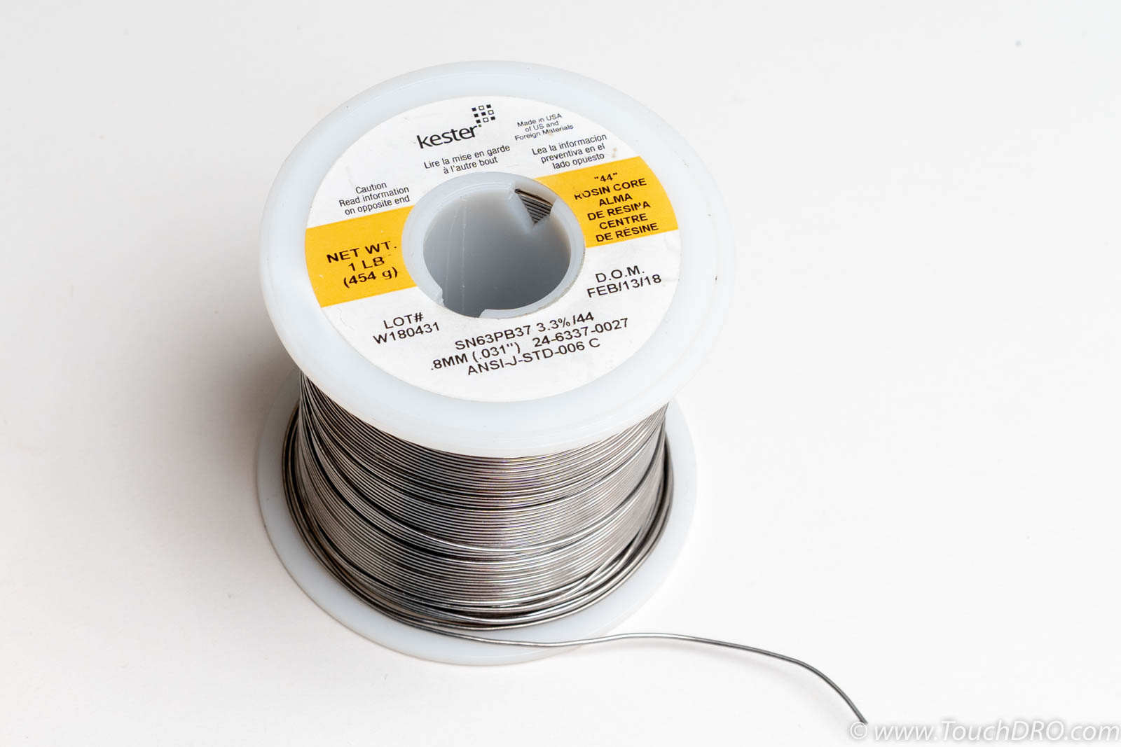
Solder intended for electronic assembly usually has a flux core. There are many different alloys and even more types of core flux; therefore, selecting the right combination is very important. Unless you have good experience with soldering, it's best to stick with leaded alloys. Two popular leaded alloys are Sn60/Pb40 and Sn63/Pb37, containing 60/40 and 63/37 tin-to-lead ratio respectively. For historical reasons 60/40 alloy is more commonly available at hobby and electronics stores, but Sn67/Pb37 works better in this case.
There are two main types of flux on the market - water-soluble and "no-clean". Water soluble fluxes are generally more aggressive and need to be thoroughly cleaned immediately after soldering. No-clean fluxes are much milder and more forgiving, so they can (and should) be left on the board after soldering.
In summary, for most hobby work that involves through-hole assembly, Sn63/Pb37 solder alloy with Rosin flux core in 0.030" diameter is ideal. A popular choice is Kester #44 Sn63/Pb37 0.031" diameter flux core solder. It's commonly sold in 1lb spools and at the time of this writing sells for around $25. Equivalent solder from other manufacturers might be available in smaller quantities too.
Flux Paste
Even though solder wire contains flux, being able to add more flux to the joint often comes very handy. For example, dipping component leads before soldering will help the solder to flow through the hole and create a better fillet on the underside. Similarly, during rework, when the flux that came from the solder wire boils off, adding a dab of fresh flux will make for a much better solder joint. Finally, when using an inexpensive soldering iron without precise temperature control, the extra flux will provide some safety margin if the joint is overheated.
For most DIY projects Rosin paste flux is best since it's non-corrosive and can be left on the board without any adverse effects. A 2 oz jar should cost no more than $10 and will last for many years of casual use if kept closed
Desoldering Wick
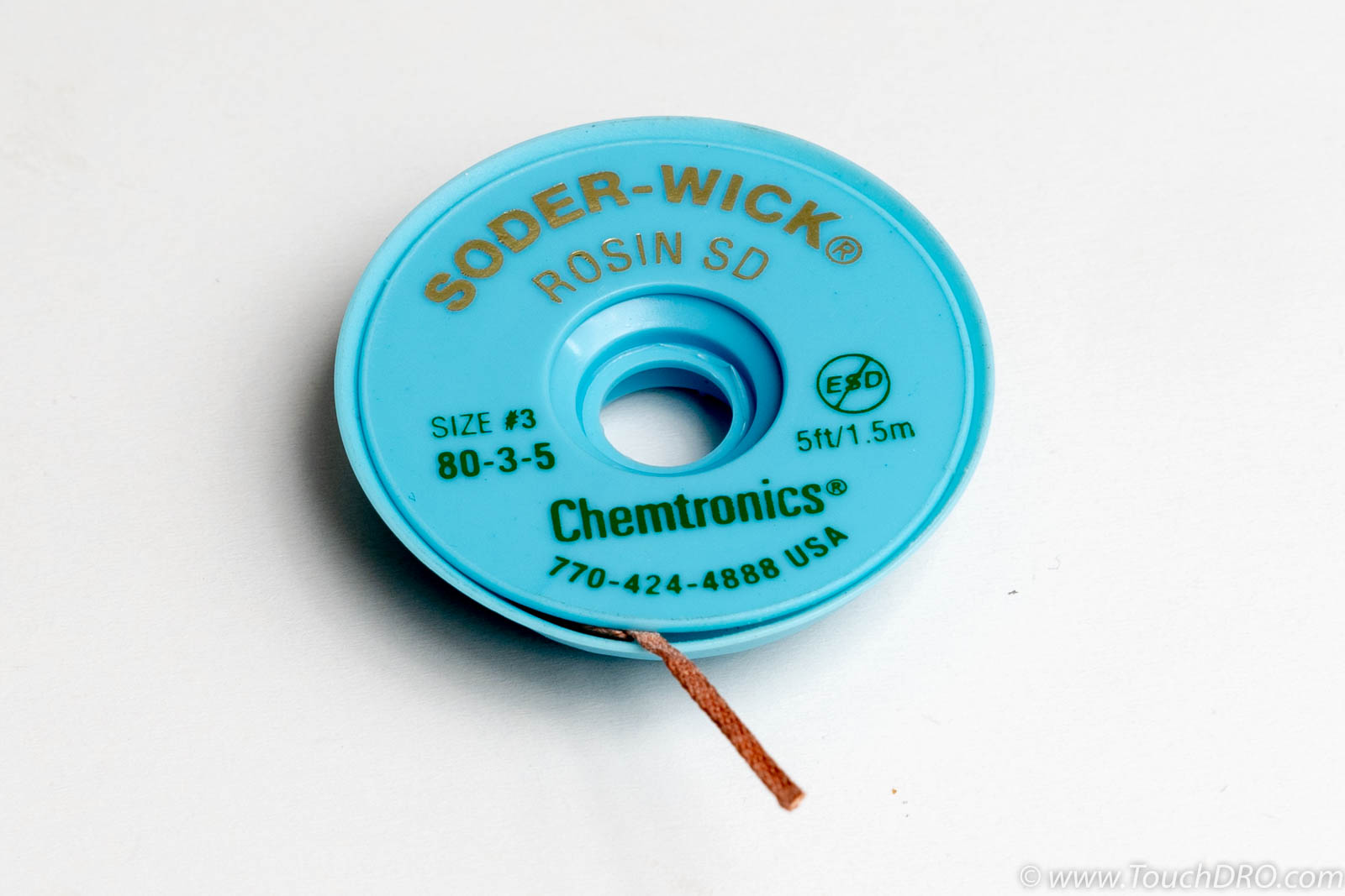
Desoldering wick, also commonly called "Desoldering Braid" or "Solder Wick", is a flattened piece of copper braid covered in rosin flux. As the name suggests, it's used to wick away solder and can be used to desolder simple parts or remove excess solder from a joint. It is usually readily available at most home improvement stores, car part stores and online retailers for well under $5 per container.
Clippers or Side Cutters
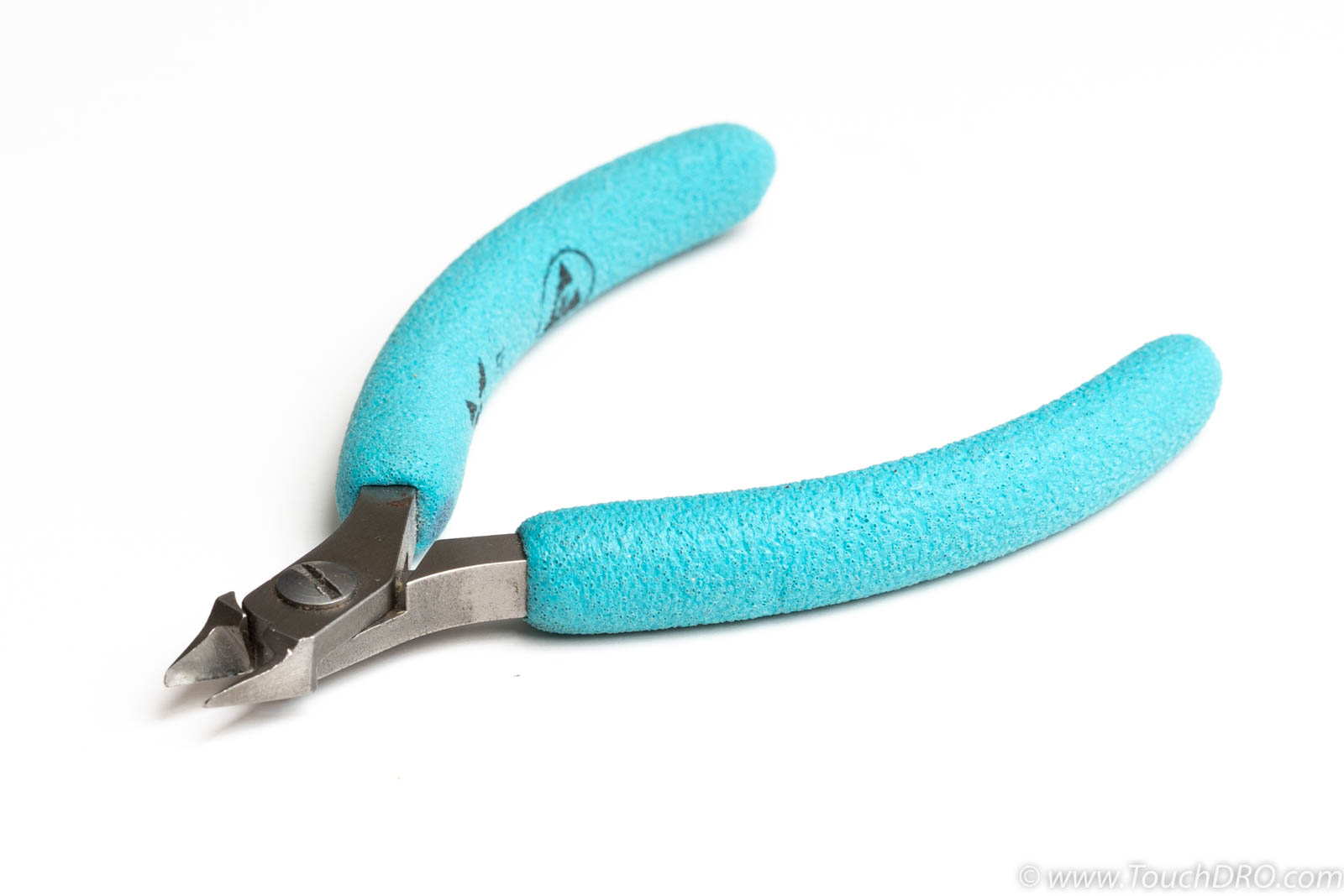
When building a DIY circuit, it's usually necessary to cut wires or trim component leads. A good pair of small clippers or side cutters is likely the second most used tool after the soldering iron. For casual use any small pair of cutters would suffice, but dedicated electrical flush-cutting side cutters are more convenient to use and cost less than $10
Needle-Nose Pliers or Tweezers
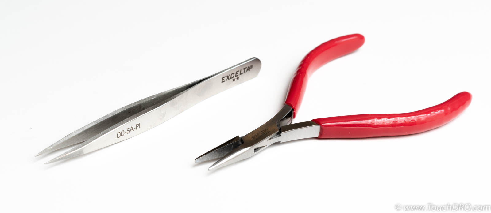
Tweezers and/or needle-nose pliers have many uses and are an essential tool when building DIY circuits. They can be used for forming component leads, holding the parts when soldering or desoldering them, and for many other things.
Part Preparation
Most electronic components, such as resistors, capacitors, diodes, leds, etc. come with leads that are too long, which usually need to be bent to match the hole distance and trimmed to length.
Axial Resistors, Capacitors and Diodes
Small resistors, diodes and ceramic capacitors most commonly come in axial configuration. That is, the leads stick out of either side of the part's body inline with it's the axis of rotation. Usually, these components are mounted horizontally (laying flat on the board) and the leads need to be bent at 90-degree angle at a certain distance from the body to fit the footprint on the board. This can be done by holding the lead in a pair of tweezers or needle nose pliers and bending the protruding lead. Since most boards use the same component lead spacing, it might be useful to put a "Sharpie" mark on the tweezer to get consistent size.
Please keep in mind, ceramic capacitors and glass diodes are very fragile and; so, it's best to avoid bending the leads right against the body or, in general, subjecting the part to mechanical stresses. Cracked capacitors will not function correctly and can fail in "closed" state if they absorb moisture. Diodes usually fail in "open" state.
Electrolytic Capacitors
Electrolytic capacitors usually come in radial configuration. I.e. the leads stick out from one side of the barrel and are placed along the centerline of the part. When the capacitor is mounted vertically, there is usually no additional prep besides cutting it off the tape if applicable. If the capacitor is to be laid flat against the board, the leads will need to be bent at a 90 degree angle. When doing so, make sure to avoid pulling on the leads since this can cause internal failures of the capacitor.
Integrated Circuits
Integrated Circuits (ICs) come in a plethora of different shapes and sizes. In most cases they don't need any additional prep or lead forming. If for some reason the leads need to be bent, it's best to avoid bending them too close to the IC's body since it can create sharp bends and can lead to lead cracking and subsequent failure.
Assembly Tips
Directional Parts
Many electronic components are directional and will not function correctly if inserted using incorrect orientation. This includes diodes, LEDs, transistors, electrolytic capacitors, integrated circuits, etc. Directional parts usually have a mark of some sort to indicate the first lead; on the PCB the orientation is usually shown on the silkscreen.
Holding Parts in Place
During the assembly process you will usually insert the parts from the top side and then need to flip the board to solder them. To prevent the parts from falling out it's convenient to slightly bend the leads outwards after the part is inserted, which will hold it in place. For pin headers or other parts with thick hard leads this will not work and holding the part with your finger while solder will likely burn your. In this case you might use a piece of masking tape to keep the part in place.
Order of Assembly
While there is usually no inherent order of assembly, it's best to add parts in order of their height. I.e. start by soldering resistors, small capacitors, and other low-profile parts. Then move on to parts that are slightly taller, and so on. This does two things. First of all, it's easier to insert and then inspect the low-profile parts without tall parts obstructing the view and access. Second, this will let you lay the board flat while soldering, which will provide for a much more stable platform.
Trimming Excess Leads
Leaving longer leads makes inserting the parts a bit easier and, once inserted, the leads can be bent to keep the part from falling out. Once the part is soldered, it's best to trim the leads before moving to the next set of parts. The leads should be trimmed a bit above the solder fillet to avoid cracking the solder joint. Please note, the trimmings are sharp and tend to fly in all directions, so it's very important to wear eye protection.
Soldering
Soldering is one of those operations that look easy, but when done incorrectly, can lead to an unending stream of reliability issues. There are three main ways that soldering can go wrong: solder bridges, cold solder, and heat damage. All three can be avoided by using correct solder alloy, enough flux and good heat control.
Flux
Flux performs two important functions during the soldering process. First and foremost, it removes oxidation from the mating surfaces to help the solder flow. Second, it keeps the surfaces and the molten solder clean during the soldering process. There are hundreds of fluxes on the market and the whole subject can be easily overcomplicated. The important parts to remember are:
Heat Control
Applying just the right amount of heat is the key to achieving a solid solder joint. During the soldering process, molten solder creates a very thin layer of alloy with the base metal that is called an intermetallic layer. Its thickness determines the electrical and mechanical properties of the joint. If too little heat is applied, the intermetallic layer will not form; so, the joint will be unreliable and will separate over time (this is called a cold solder joint). Counterintuitively, applying too much heat too fast will result in the same issue: if the flux boils off before the solder starts flowing, an oxide layer will form on the surfaces, preventing formation of the intermetallic layer. Conversely, applying heat for too long will result in excessively thick intermetallic layer, which will result in a brittle solder joint that might fail over time as well. Furthermore, overheating can lead to premature failure of many components such as ICs, electrolytic capacitors, etc.
To ensure good connection it's crucial to use soldering iron set to the correct temperature range. For Sn63/Pb37 solder 230°C/450°F is a good starting point. Always preheat both surfaces by touching them with the tip of the soldering iron for a few seconds. Then touch the solder wire to the junction between the component lead and the through-hole. If the surfaces are at the right temperature, you will see the solder flowing onto both surfaces. If it doesn't, pull back the wire, heat the surfaces for a few more seconds, and try again. Once the solder flows around the hole, wait for another second and remove the tip. The result should be a shiny concave solder fillet. Dull joint usually means that too much heat was applied and the flix burned off; convex fillet means either not enough heat or way too much solder was applied. To fix this, apply a bit more flux, clean the tip of the iron and reheat the joint just until the solder melts.
Solder Bridges
Solder bridges are very common when soldering multi-lead or closely spaced components such as ICs, pin headers, etc. Almost always they are a result of flux burning off, which reduces the surface tension of the molten solder. The easiest way to fix a bridge is to wait for the joint to cool down, apply a bit of flux (paste flux or flux pen come handy in this case) and reflow it by briefly melting the solder. If the bridge doesn't go away, there might be too much solder. In this case, wick away excell solder, either using a desoldering braid or cleaning the tip of the iron and "pulling away" the solder to it. Then let the joint cool down and reapply fresh solder.