DRO Adapter Components
A TouchDRO scale interface adapter is a digital microcontroller circuit whose job is to receive and process the signal from various DRO scales and send position data to the application. Since the TouchDRO system is designed to work with many different types and models of scales and encoders, there are a few different adapters. Conceptually, those adapters consist of smaller building blocks that are combined in various ways to work with different scales. This article provides a cursory overview of what those building blocks are in order to make sure that you build or buy the correct TouchDRO adapter.
Control Circuit
At the heart of a TouchDRO controller is the main control circuit that is responsible for doing all of the data processing and communication. It consists of the following three logical components:
The Microcontroller
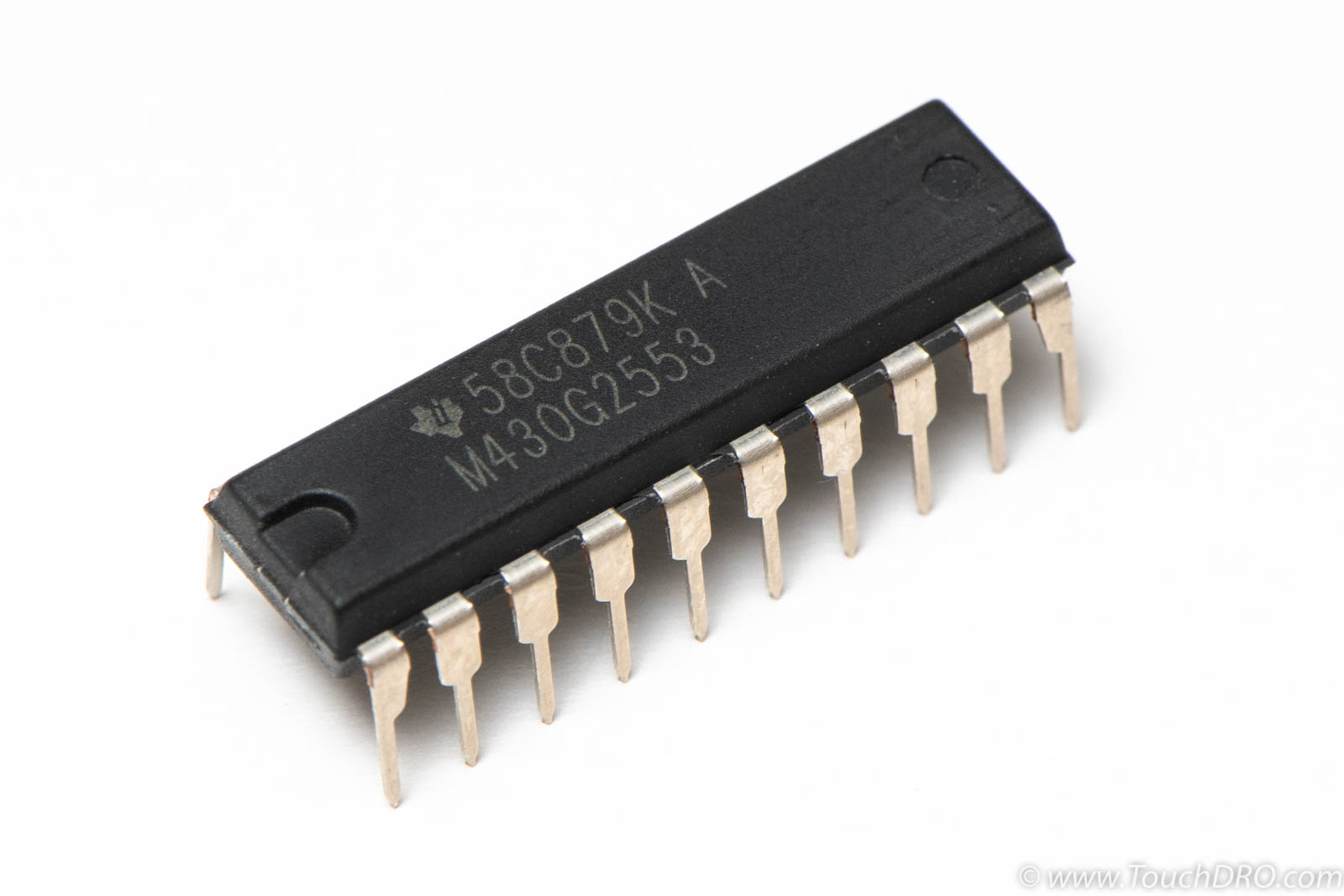
The microcontroller is the brain of a TouchDRO scale adapter and is basically a miniature self-contained computer that has a processor, RAM, non-volatile memory, inputs, and outputs. It does all of the work involved in receiving a signal from the scales, converting it to a usable value and passing it along to the communication device.
Bluetooth Module
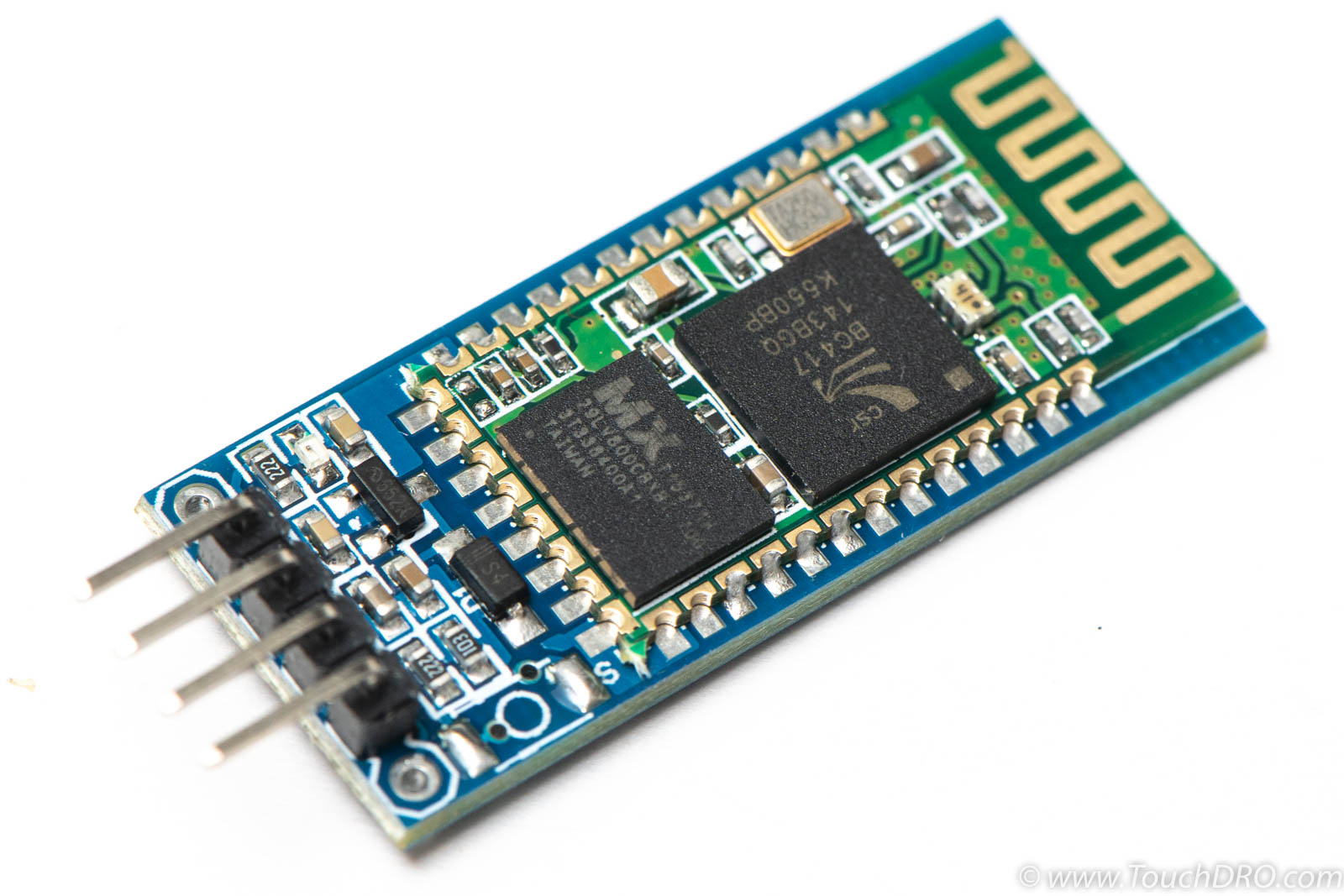
The microprocessor TouchDRO uses can't communicate with the application directly. Instead, it relies on a dedicated off-the-shelf BlueTooth transceiver module to send the data to the tablet.
Voltage Regulator
The microcontroller and the BlueTooth module require a clean and stable DC supply voltage of 3.3 Volts. A "wall wart" AC-DC converter can't provide the well-regulated voltage needed by those devices, so an on-board voltage regulator is needed.
Firmware
Just like your home PC would be useless without its software, the microcontroller would be without it's firmware. TouchDRO firmware is a custom piece of embedded software written for the particular microcontroller that performs some combination of the following tasks:
Initialization logic
Different scales have different input requirements, so the microcontroller has to have correct pull-up and/or pull-down resistors enabled. The firmware configures input pins on startup based on the type of scale protocol.
Protocol detection (optional)
The firmware that supports multiple-scale protocols has to be able to detect which scales are connected to each input. This is done during the first few seconds after boot up.
Input Pulse Processing
As raw pulses come from the scales, the firmware has to immediately capture them and store the value for future processing. Since scale signals are not predictable (in most cases scales decided when to send the stream), the firmware has to always be ready to receive and record the signal.
Position Counter (optional)
Quadrature encoders, such as glass and magnetic scales, don't have an internal logic to keep track of the position. Instead, they send raw pulses as the scale is moved. It's up to the DRO to keep track of the current position by incrementing or decrementing a value stored in memory. This is what the position counter is tasked with doing.
Datastream Decoder (optional)
Capacitive scales process raw encoder signals internally and periodically send the position to the adapter encoded using their particular data format. The firmware has to detect the beginning and the end of the stream and decode the data into normalized units.
Position Transmission
Several times per second (depending on the version) the firmware needs to convert the current position values to a standard format and send it to the UART controller for transmission.
Scale Power Supply
In order to operate correctly, DRO scales require specific DC voltage that might or might not be different from the voltage used by the microcontroller. Scales that use 1.5V or 5V supply voltage need a separate power supply, but even when using 3V scales, it might be desirable to power them from a separate power source (a battery bank, for example).
There are a few ways to provide the needed power supply:
External Voltage Source
The simplest approach is to add a second external power supply for the scales. For instance, scales that use a 1.5V power supply can be powered from a single "AA" cell for many months or even years. Similarly, if the main controller circuit is powered by a 5V regulated power supply (a phone charger, for instance), the same 5V supply can power glass or magnetic scales.
Voltage Divider
Capacitive scales that use 1.5V supply draw a very small amount of current in the Microampere range. Using a separate 1.5V voltage regulator might be unnecessary or even impossible since many voltage regulator chips need the load that draws a minimum current of several Milliamperes. In such a case, a simple voltage divider using two resistors will do the job just fine.
Secondary Voltage Regulator
When a 5V supply is needed, a common approach is to have a second voltage regulator powered from the same input as the microcontroller voltage regulator. Care must be taken to ensure that the input voltage is high enough to account for the dropout voltage of the regulator.
Step-Up DC-DC Converter
In case when the input voltage is not high enough to be used with a voltage regulator, an off-the-shelf inexpensive DC-DC boost converter can be used.
Input Stage
Microcontroller input pins have very strict voltage and current requirements. Similarly, many scales have specific input impedance needs. Very often, the two are not compatible, thus necessitating additional circuitry to operate correctly. For the lack of a better term, we can call this the "Input Stage". This stage can perform one or more of the following functions:
Signal Conditioning
The output signal from some scales might have excessive noise or voltage spikes. This can cause problems ranging from false pulses that throw off the reading to component damage. As a bare minimum, each scale input should have a bypass capacitor installed between positive and negative lines. Furthermore, many inductive and magnetic scales might cause negative voltage spikes on their signal lines and require flyback diodes.
Voltage Amplification
DRO scales output a stream of high and low pulses that need to be interpreted by the microcontroller as 0s and 1s by crossing the predefined voltage thresholds for "high" and "low" values. 1.5V scales' signal is too low and can't be reliably read by the microcontroller running at 3.3V and needs to be amplified.
Voltage Reduction
A microcontroller designed to run at 3.3V can be permanently damaged when subjected to a 5V signal. Many quadrature scales and rotary encoders output 5V signal that needs to be reduced to the safe level.
Differential Signal Decoding
Many modern glass and magnetic DRO scales provide a differential signal that consists of two complementary signals that are mirror images of each other. Since the microcontroller can't directly handle the differential signals, a special differential signal decoder circuit is needed.
Summary
As is evident from this article, a TouchDRO controller is not a monolithic device and, instead, consists of several logical components. By combining the base control circuit with appropriate firmware, input stage and power supplies, TouchDRO adapters can work with many different types and models of scales. Furthermore, since many components are shared between different adapters, it's relatively easy to modify an existing adapter to work with different scales, etc.