DIY DRO Adapter Kit
DIY DRO Adapter Kit (Unassembled) is based on the second generation 32-bit TouchDRO hardware. It supports up to four scale inputs, tachometer input, and touch probe/tool setter input. The kit includes a bare printed circuit board, a microcontroller pre-programmed with 32-bit TouchDRO Universal firmware, and all of the components needed for building a TouchDRO adapter.
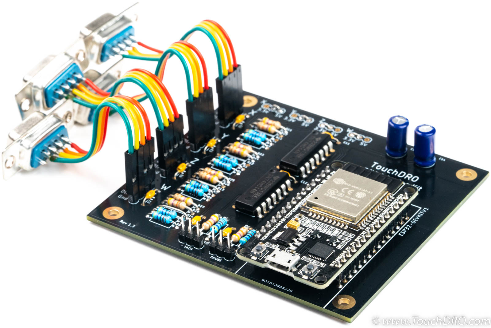
The DIY Digital Readout Adapter Kit is designed from the ground up to be cost-effective, easy to build and offers excellent performance and reliability. The kit comes pre-programmed with the second generation universal TouchDRO firmware and supports most modern 5V Glass and Magnetic DRO scales and many 3.3V capacitive scales. Each input line can be individually configured to provide 5V or 3.3V supply voltage.
The circuit uses a dedicated Schmitt trigger to provide fast 5 Volt-tolerant input for standard Glass and Magnetic scales and the necessary noise protection for the capacitive scales. In conjunction with the optimized 32-bit firmware, it can handle 1 micron DRO scales moving at 100 mm per second (100KHz edge rate). At the same time it can extract maximum performance from the iGaging/Shahe Capacitive DRO scales by applying digital filtering and glitch rejection.
Kit Contents
This kit comes with high-quality name brand components that are derated to provide ample headroom for long-term reliability and durability.
DRO Adapter Only

- Printed circuit board (HASL finish), electrically tested and inspected to meet IPC-A-600 Class II standard
- ESP32 DevkitC module
- Set of Texas Instruments ICs (74xx14)
- HIgh-quality Panasonic electrolytic capacitors
- Name brand resistors and capacitors
DRO Adapter With DB9 Connectors

In addition to the above, this options includes:
- D-Sub 9 connectors
- Pin headers
- Jumper wires for connecting various scale configurations
To complete the build, you will need to provide a set of compatible scales, a suitable non-metallic enclosure and a 5V 500mAh Micro-USB power adapter (an old phone charger works great for this purpose).
Each circuit board is fully electrically tested by the manufacturer. Additionally, I personally program and test every microcontroller, inspect each PCB, and check the kit before shipping it out.
Specifications
Features
- Supports four linear axis inputs, tachometer, and a touch probe or tool setter input
- Scale inputs are 5V tollerant and can be individually configure for 5V or 3.3V scales
- Per-scale bypass capacitors filter out transient spikes on the power supply lines
| Scale Inputs | 4 |
|---|---|
| Tachometer Input | Yes |
| Probe/Height Setter | Yes |
| Power Supply | 5V DC |
| Current Draw | Approx. 300 mA |
| Width | 87 mm (approx 3.4") |
| Length | 78 mm (approx 3.1") |
Supported Scales
This TouchDRO adapter supports a wide array of Glass and Magnetic DRO scales, many standard rotary encoders that output a quadrature signal with a 5V level, iGaging EZ-View DRO scales, iGaging Absolute DRO scales, and Shahe Remote DRO Linear Scales.
To ensure that your particular scales are supported, please refer to their documentation. For glass/magnetic scales, ensure that the scales use positive 5V power supply voltage and output quadrature signal with a 5V level.
For more information about supported quadrature scales, refer to the pages linked below:
For capacitive scales, if your displays looks like one of the displays below (including color and markings), this adapter will work with them. This includes:
- iGaging EZ-View DRO Plus
- iGaging DigiMag (and it's rebranded variants)
- iGaging Absolute DRO Plus
- Shahe 5403-xxx "Digital Liner DRO Scales with Round Display"
- Shahe 5403-xxxA/F "Digital Liner DRO Scales with Square Display"

Mechanical Drawings

Circuit Schematic

Bill Of Materials
This DIY DRO kit includes all of the components needed to assemble a TouchDRO adapter.
| Value | Description | Qty. | Reference |
|---|---|---|---|
| PCB | TouchDRO Adapter PCB, Tin/Led Plated, Green solder mask, White silkscreen | 1 | N/A |
| ESP32 Devkit V1 | ESP32 WROOM Dev. Kit | 1 | U1 |
| 74xx14 | SN74HC14N Hex Schmitt Trigger | 2 | IC1, IC2 |
| Capacitor, 100 uF | Cap. electrolytic, 100uF, 35V | 2 | C14, C15 |
| Capacitor, 0.1uF | Cap. ceramic, 0.1uF 50V | 8 | C1, C3, C5, C7, C9, C10, C11, C12 |
| Resistor, 4.7 KOhm | Metal film resistor, 4.7 KOhm, 1/4W, 5% | 10 | R1-10 |
| Resistor 47KOhm | Metal film resistor, 47 KOhm, 1/4W, 5% | 10 | R21-R30 |
| Pin Header | Pin Header, 4x1, 1" spacing | 4 | X,Y,Z,W |
| DB9 Connector | DSUB-9 Femal, 9 Pins | 4 | X,Y,Z,W |
| Jumper Wires | Dupond Jumper Wire, 100mm | 8 | X,Y,Z,W |
Documentation & Resources
Useful Resources
Port Functions
| Port | Description | 5V-Tolerant | Note |
|---|---|---|---|
| X,Y,Z,W | Inputs for four linear axes | Yes | Pulled up to scale Vcc |
| Tach. | Tachometer input | Yes | Pulled up to 5V |
| Probe | Touch probe input | Yes | Pulled up to 5V |
| Power | 5V Power input | N/A | USB Micro-B |
Axis Inputs
TouchDRO DIY DRO Adapter Kit supports up to four axis inputs. During the assembly, the inputs can be individually configured to work provide 3.3V or 5V power supply to each axis. Data lines for the input will be pulled up to the selected Vcc voltage.
Tachometer
The board supports non-directional tachometer input. The tachometer input pin is pulled up to 5V ; the tachometer should provide a sinking (NPN/open-collector) or push/pull output.
Touch Probe
Touch probe input is a binary on/off input. The pin is pulled up to 5V. The firmware can handle either a normally-open or normally-closed probe. During boot time, it detects the state of the input and assumes that the probe is in the "Off" state; the opposite state will be treated as "On".
Power Input
The board is powered by a standard 5V regualted power supply, such as a phone charger, etc. For best results, a power supply should provide at least 500 mA of current.
Grounding
Proper grounding is very important for the stable operation of your DIY DRO setup. In order to reduce EMF issues, ground the board to the machine's frame and ensure that the scales' cables are connected to the ground only on one side. Mounting holes on the board are tied to the ground fill, as are all of the ground pins. For more details please refer to the "Avoiding Common DRO Scale Problems" page.