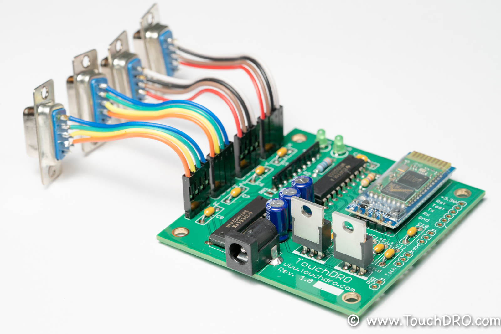
TouchDRO DIY DRO Adapter Kit for Glass Scales (Unassembled) supports up to four 5V quadrature scale inputs, tachometer
input, and touch probe/tool setter input. It includes a bare printed circuit board, a microcontroller pre-programmed
with TouchDRO firmware, and all of the components needed for building a TouchDRO adapter.
The DIY Digital Readout Adapter Kit for Glass/Magnetic Scales is designed from the ground up to be cost-effective,
easy to build and offers excellent performance and reliability. It supports the vast majority of modern Glass and
Magnetic DRO scales, as well as standard rotary encoders that output a single-ended 5V quadrature signal. During
the assembly, the inputs can be configured to work with PNP, NPN, and Push/Pull encoders for added flexibility.
The adapter uses a fast digital buffer to provide 5 Volt-tolerant input for standard single-ended Glass and Magnetic
DRO scales and other quadrature encoders. In conjunction with the optimized TouchDRO quadrature firmware, it can
handle a 5-micron movement speed of at least 100mm/second (4 inches/second) when a single axis is in motion or
at least 50mm/second when all four axes are moving at once.
This DIY adapter can be used with Glass and Magnetic DRO scales that output a differential signal by omitting
the complementary line connections, but for those scales, the pre-made TouchDRO Adapter for Glass and Magnetic
scales is recommended.
Kit Contents
This kit comes with high-quality name brand components that are derated to provide ample headroom for long-term
reliability and durability. This includes:
Printed circuit board (HASL finish), electrically tested and inspected to meet IPC-A-600 Class II standard
TI MSP430 microcontroller, preprogrammed with TouchDRO firmware
Tested HC-05 BlueTooth transceiver
Set of Texas Instruments ICs (74xx244 buffer and two LM1117 voltage regulators)
HIgh-quality Panasonic electrolytic capacitors
Name brand resistors, capacitors, and LEDs
D-Sub 9 connectors, pin headers, and jumper wires for connecting various scale configurations
To complete the build, you will need to provide a set of compatible Glass or Magnetic DRO scales, a suitable
non-metallic enclosure and a 7.2V-9V AC/DC power adapter with a center-positive 5.5mm barrel connector.
Each circuit board is fully electrically tested by the manufacturer. Additionally, I personally program and test
every microcontroller, inspect each PCB, and check the kit before shipping it out.
Specifications
Features
Supports four linear axis inputs, tachometer, and a touch probe or tool setter input
Scale inputs can be configured for use with PNP, NPN, and push/pull sensors
Two separate onboard linear voltage regulators provide clean power supply voltages to the 5V scale rail and
3.3V logic rail
Per-scale bypass capacitors filter out transient spikes on the power supply lines
Scale Inputs
4
Tachometer Input
Yes
Probe/Height Setter
Yes
Power Supply
7.2V DC - 9V DC
Current Draw
Approx. 200 mA
Width
2.7"
Length
2.8"
Supported Scales
This TouchDRO adapter supports a wide array of Glass and Magnetic DRO scales, as well as many standard rotary
encoders that output a quadrature signal with a 5V level. This includes most, if not all, brands of budget
Chinese Glass and Magnetic DRO scales, as well as the vast majority of modern brand-name DRO scales.
To ensure that your particular scales are supported, please refer to their documentation to ensure that the
scales use positive 5V power supply voltage and output quadrature signal with a 5V level.
For more information about Glass and Magnetic DRO scales, refer to the pages linked below:
Mechanical Drawings
Fig 1: Mechanical Dimensions
Circuit Schematic
Fig 2: Circuit Schematic
Kit Contents
This DIY DRO kit includes all of the components needed to assemble a TouchDRO adapter.
Value
Description
Qty.
Reference
PCB
TouchDRO Adapter PCB, Immersion Gold plated, Green solder mask, White silkscreen
1
N/A
MSP430G2553
16-Bit mixed-signal microcontroller (pre-programmed)
1
U1
74xx244
SN74HC244 Octal Buffer
1
U1
HC-05
Bluetooth Transceiver, Slave
1
HC-05
LM1117T-3.3
Voltage Regulator, 3.3V 800 mA, LDO
1
LM1117
LM1117T-5.0
Voltage Regulator, 5.0V 800 mA, LDO
1
LM1117
Capacitor, 100 uF
Cap. electrolytic, 100uF, 35V
3
C1, C2, C3
Capacitor, 0.1uF
Cap. ceramic, 0.1uF 50V
12
C4-C15
Resistor, 330 Ohm
Metal film resistor, 330 Ohm, 1/4W, 5%
2
R2, R3
Resistor 47KOhm
Metal film resistor, 47 KOhm, 1/4W, 5%
1
R1
Resistor Network
Resistor Network, 47KOhm, 10 Pin
1
RN1
LED
LED, Green 3mm, 20 mA
2
HB, PWR
Pin Header
Pin Header, 4x1, 1" spacing
5
X,Y,Z,W, HC-05 (optional)
Scale Connector
D-Sub 9 Pin, Female, Panel Mount
4
N/A
Power Jack
2.1x5.5 mm power input jack, PCB mount
1
Pwr
Documentation & Resources
Port Functions
Fig 3: Input Ports
Port
Description
5V-Tolerant
Note
X,Y,Z,W
Inputs for four linear axes
Yes
Pulled up/down depending on RN1 position
Tach.
Tachometer input
No
Pulled up to 3.3V
Probe
Touch probe input
No
Pulled up to 3.3V
Power
7.2V-9V Power input
N/A
2mm x 5.5mm barrel, center positive
PROG
Programming Port
No
Used to re-program MSP430
Note that the scale inputs on this adapter are 5-Volt tolerant since they are connected to the TTL digital buffer IC. On the
other hand, the tachometer and probe inputs are not 5V-tolerant since they are connected directly to the MSP430
microcontroller and will be damaged by voltage exceeding 3.3V.
TouchDRO DIY DRO Adapter Kit for Glass Scales supports up to four quadrature axis inputs. During the assembly,
the inputs can be configured to work with NPN, PNP, and Push/Pull sensors by altering the location of the pull
up/down resistor array.
Tachometer
The board supports non-directional tachometer input with a frequency range of 1Hz to 10KHz. The tachometer input pin is pulled up to 3.3V via an internal resistor; the tachometer should provide a sinking (NPN/open-collector) or push/pull output.
Touch Probe
Touch probe input is a binary on/off input. The pin is pulled up to 3.3V via an internal resistor. The firmware can handle either a normally-open or normally-closed probe. During boot time, it detects the state of the input and assumes that the probe is in the "Off" state; the opposite state will be treated as "On".
The board uses a center-positive 5.5mm x 2.1mm power input jack. The on-board voltage regulators can use supply voltage ranging from about 3.6V DC to 12V DC and can work with a range of power supplies. For best results, a power supply should provide at least 200 mA of current and 7.2V to 9V.
A 2-pin "Pwr." header is wired in parallel with the power jack. It provides an option to use a panel-mounted
power jack with an inline On/Off switch.
Grounding
Proper grounding is very important for the stable operation of your DIY DRO setup. In order to reduce EMF issues, ground the board to the machine's frame and ensure that the scales' cables are connected to the ground only on one side. Mounting holes on the board are tied to the ground fill, as are all of the ground pins. For more details please
refer to the "Avoiding Common DRO Scale
Problems " page.