Build a DIY Touchscreen DRO for Your Milling Machine or Lathe
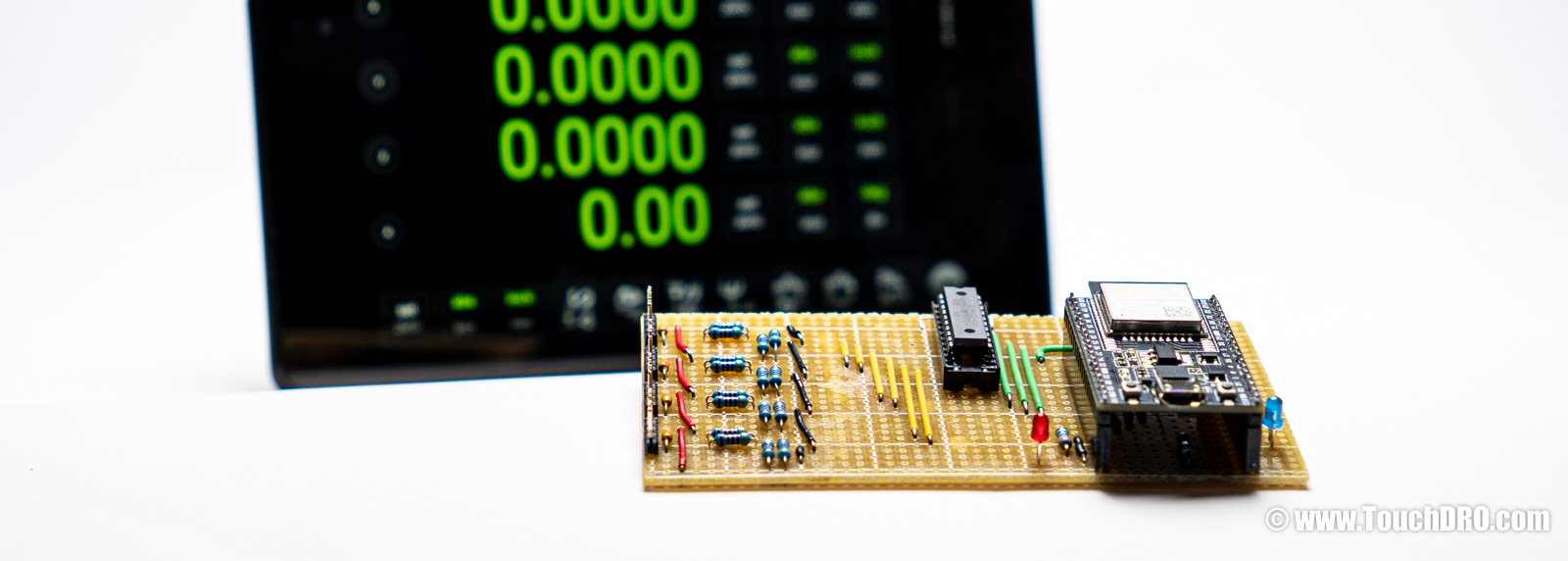
TouchDRO is a DIY-friendly digital readout system. It started as a DIY project back in 2012—when many people built adapters around an Arduino Uno and whatever parts they could source locally. Today we also sell turnkey adapters, but building your own TouchDRO adapter is still very much possible. If you're considering a DIY DRO, you have three practical paths:
- From scratch: flash our free firmware, use the TouchDRO Community app, and design/build your own interface circuit, connectors, and enclosure.
- Module + board: get the $99 module + board bundle, then add your own connectors and enclosure.
- Complete kit: buy the full TDK-40 kit for the fastest, lowest-risk DIY build.
If you'd rather write your own firmware, you can—TouchDRO's Bluetooth protocol is straightforward to implement. This page focuses on the supported DIY options using TouchDRO firmware.
TouchDRO Adapter Options at a Glance
| From Scratch | TDK-40 DIY Kit | Pre-Assembled | |
|---|---|---|---|
| Best if you want | Full control over your own hardware design | To build it yourself and still get Plus features | A turnkey DRO with tach, probe, and full warranty |
| Price | Under $50 for electronics (excludes enclosure, connectors, cables) |
$149 complete or $99 module + board or $59 module only |
$259–$299 |
| TouchDRO App Learn more | Community | Plus (included) | Plus (included) |
| Works First Try | Depends on your skills | Usually yes | Yes |
| Time to Build | 8+ hours | 1–2 hours | None |
| Support | Self-supported | Docs + community | Full support + 5-year warranty |
| Inputs & Scale Support | |||
| Glass/Magnetic Scales | Yes | Yes | Yes |
| Capacitive Scales | No | Yes | Yes |
| Reference Track | No | No | Yes |
| Tach Input | No | Yes | Yes |
| Probe Inputs | No | No | Yes |
Ready to build? Get the TDK-40 DIY Kit for the fastest path to a working DRO. Just want it to work? Skip the soldering and get a fully assembled milling machine DRO or metal lathe DRO with full support and a 5-year warranty.
How to Build a Do-it-Yourself DRO (Electronics Overview)
If you’re looking for a step-by-step walk-through of how to build a do-it-yourself digital readout for your mill or lathe, start with the DIY DRO Build Overview . That page covers the big-picture process: choosing scales, mounting them on the machine, and wiring everything to a DRO adapter (encoder interface box).
This guide focuses on the electronics side of a DIY tablet-based DRO—how to use the TDK-40 platform or a bare ESP32 module as the core of your own adapter (encoder interface box). The build options described above (kit, module plus carrier board, or free firmware) map to a few common hardware setups:
- TDK-40 kit or carrier board as a drop-in front end. You use the TDK-40 carrier board for all of the scale input conditioning (quadrature, SPC, BIN6, etc.), and your DIY work is mainly mechanical: connectors, enclosure, and wiring.
- Custom carrier board around a pre-programmed TDK-40 module. The ESP32 module handles all of the DRO logic and firmware, while your board provides the exact mix of buffered quadrature inputs and serial channels you need for your glass, magnetic, or capacitive scales. For this setup, most people start with the pre-programmed TDK-40 module .
-
Simplified ESP32 adapter with free firmware.
For a bare-bones build, you can design a small board with just enough buffering for a few quadrature
A/Binputs and pair it with the free firmware image—ideal for a low-cost DRO on a single machine or a dedicated axis such as a tailstock or rotary table.
The sections below dig into how the DIY kit compares to the pre-assembled adapters, what you need to know about the ESP32 hardware, and how to upload the firmware so you can choose the approach that best matches your budget and comfort level with electronics.
DIY Kit vs. Pre-Assembled TDA-4xx Adapter Differences
The DIY kit and the à-la-carte TDK-40 module use the same “Plus” version of the firmware as the pre-assembled mill and lathe DRO adapters. They offer the same core performance as the pre-made boards, can read the same scale protocols (including quadrature, SPC, and BIN6), and provide access to TouchDRO Plus application features. This generation of DIY options is fully featured, with the same scale support and input circuitry as the pre-assembled adapters; the main differences are in convenience features and warranty coverage.
In practical terms, the pre-assembled TDA-4xx adapters add several extras that the DIY kit and bare TDK-40 module do not include:
- Auxiliary inputs: pre-assembled adapters include one (TDA-410) or two (TDA-420) auxiliary inputs for an RPM sensor or a touch probe/tool-height setter.
- Scale reference input: they provide a dedicated reference input, so you can zero a scale at a known reference position.
- Position retention: TDA-4xx adapters can preserve scale position across power loss (as long as the scale is not moved while power is off).
- Warranty: pre-assembled adapters include a 5-year warranty; DIY kits and à-la-carte parts do not carry warranty coverage.
If you want the simplest path to a fully featured, long-term DRO with all of the convenience features already built in, a pre-assembled TDA-4xx adapter is usually the best choice. The DIY kit and à-la-carte TDK-40 module are a good fit if you enjoy electronics work, are comfortable giving up a few convenience features and the warranty, and would like to save some money or build something customized to your machines.
For a side-by-side feature comparison between the DIY options and the TDA-4xx adapters, see TouchDRO Adapter Feature Comparison .
Technical Details
All current-generation TouchDRO adapters are built around the ESP32 system-on-chip. The DIY kit and custom circuits use the same ESP32 core but are based on the ESP32-DevKitC-32E module for convenience since it includes an onboard voltage regulator, a USB-to-serial interface, and other supporting components. The pre-programmed module ships with the TouchDRO Plus firmware. The free firmware is pin-compatible but does not include TouchDRO Plus and cannot be upgraded to it.
ESP32-DevKitC-32E on Mouser: https://www.mouser.com/ProductDetail/Espressif-Systems/ESP32-DevKitC-32E
| Signal | GPIO | ESP32-WROOM Pin | DevKitC Header Pin |
|---|---|---|---|
| X axis A | GPIO25 | Pin 10 (IO25) | J2 pin 9 (D25) |
| X axis B | GPIO26 | Pin 11 (IO26) | J2 pin 10 (D26) |
| Y axis A | GPIO4 | Pin 26 (IO4) | J3 pin 32 (D4) |
| Y axis B | GPIO27 | Pin 12 (IO27) | J2 pin 11 (D27) |
| Z axis A | GPIO16 | Pin 27 (IO16) | J3 pin 31 (D16) |
| Z axis B | GPIO17 | Pin 28 (IO17) | J3 pin 30 (D17) |
| W axis A | GPIO18 | Pin 30 (IO18) | J3 pin 28 (D18) |
| W axis B | GPIO19 | Pin 31 (IO19) | J3 pin 27 (D19) |
| Heartbeat LED | GPIO2 | Pin 24 (IO2) | J3 pin 34 (D2) |
| Status LED | GPIO12 | Pin 14 (IO12) | J2 pin 13 (D12) |
The ESP32 should not be connected directly to the scales, even if the signal voltage looks safe. The input pins on the ESP32 have no built-in protection or signal conditioning. If any signal goes above 3.6 V, the ESP32 can be permanently damaged. The input pins also don’t have Schmitt triggers, which means they need clean, sharp pulses to read the scales reliably.
Because of this, you must use a proper buffer or interface circuit between the scales and the ESP32. For most DIY builds, the TDK-40 carrier board is the recommended option — it already includes the correct input circuits for both single-ended (TTL) and differential (RS-422) scales, so you don’t need to worry about the electronics. If you choose to design your own interface for special or older scales, we assume you’re comfortable working with electronics and understand how to create a safe, reliable input stage for the ESP32.
Firmware Upload Instructions
The firmware bundle can be downloaded here: touchdro-free-v3.2.zip. To flash it, you will first
need to install the Espressif tool set (including esptool.py) by following the instructions on
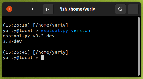
Espressif’s website. After installation, verify that esptool is working by running
esptool.py version from your command prompt or terminal.
Once the tool set is installed and verified, unzip the firmware files into a directory and open that directory in
your command prompt or terminal. Run the appropriate command for your operating system as shown below, making sure
to replace <port number> (or device name on macOS/Linux) with the correct serial port for your
ESP32 module.
On Windows, run this:
esptool.py ^
-p <your port number> ^
-b 460800 ^
--before default_reset ^
--after hard_reset ^
--chip esp32 write_flash ^
--flash_mode dio ^
--flash_size detect ^
--flash_freq 40m ^
0x1000 bootloader.bin ^
0x10000 partition-table.bin ^
0x20000 touchdro-v3_2-free.bin
On OSX or Linux run this:
esptool.py\
-p /dev/<the tty device name>\
-b 460800\
--before default_reset\
--after hard_reset\
--chip esp32 write_flash\
--flash_mode dio\
--flash_size detect\
--flash_freq 40m\
0x1000 bootloader.bin\
0x10000 partition-table.bin\
0x20000 touchdro-v3_2-free.bin
The output from the command should look similar to this:
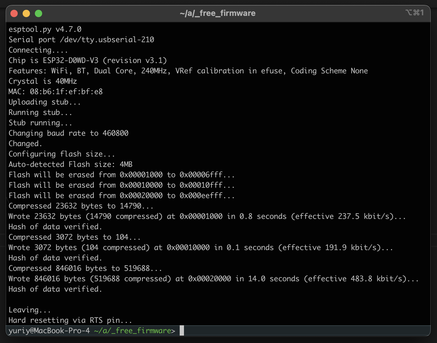
Now is a good time to check that the module works as expected. Power it from a USB power supply (the USB port on the computer might not be able to provide enough current for the Bluetooth transmitter) and pair the module to the tablet. Your module will appear as TouchDRO-Free in the device list.
Open the TouchDRO application and connect to the newly paired device. You will not see readings since there is nothing connected to the inputs, but the app should stay connected. If it fails to connect or quickly drops the connection, something is wrong with the module. Try reprogramming it, or use a different module if the problem persists.
Scale Connection Basics
The TouchDRO Plus firmware (preloaded on the pre-programmed TDK-40 ESP32 module) can read several common DRO scale types:
-
Optical and magnetic DRO scales that output quadrature
A/Bsignals (see Glass DRO Scales and Magnetic DRO Scales ). - Mitutoyo Digimatic / SPC scales and other Mitutoyo-compatible SPC outputs.
- iGaging Absolute DRO Plus scales (Mitutoyo-compatible SPC protocol).
- Chinese capacitive scales and calipers that output BIN6 serial data (covered in more detail in the Capacitive DRO Scales overview ).
Note: the free firmware image described later on this page supports only basic quadrature A/B inputs.
For full protocol support and advanced features, you will need
TouchDRO Plus firmware
on a pre-programmed TDK-40 module.
Quadrature Glass and Magnetic Scales
Most modern (and many legacy) glass or magnetic DRO scales run from a 5 V supply and output 0–5 V square-wave quadrature signals, either single-ended (TTL) or differential (RS-422).
The TDK-40 carrier/main board used in the TouchDRO TDK-40 DIY kit is designed specifically for these scales. It includes RS-422 line receivers that also handle single-ended quadrature inputs cleanly.
For that reason, we strongly recommend using the
TDK-40 carrier board
and fabricating simple connector pigtails to match your scale connectors. Once the pigtails are wired, hookup is
straightforward: plug each axis into the correct header. The pins for +5 V, 0 V,
A, and B are clearly labeled next to each input header on the PCB.
Mitutoyo Digimatic / SPC Scales
Mitutoyo Digimatic scales use an open-collector serial output in SPC format and a proprietary 10-pin round data connector. To connect these scales to a DIY touchscreen DRO, you will typically use a Digimatic SPC cable such as the Mitutoyo 905338 Digimatic SPC Connecting Cable (or an equivalent compatible cable) together with a small interface circuit.
On the SPC cable connector, the relevant signals and their mapping to TouchDRO are:
- Pin 8 – CLOCK → TouchDRO input A
- Pin 9 – DATA → TouchDRO input B
- Pin 10 – GROUND → common ground between the scale and TouchDRO
- Pin 6 – REQUEST → held low (pulled to ground through the interface circuit)
The scales are powered from their internal battery or external Mitutoyo power supply. The TouchDRO adapter does not provide power to the scales; it only reads the SPC signals and shares a common ground.
Using the TDK-40 Carrier Board
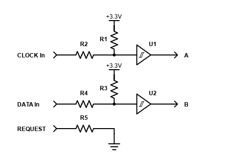
With TouchDRO Plus firmware, SPC scales can be connected directly to one of the TDK-40 SPC/BIN6 inputs. A minimal interface (shown in the diagram below) typically includes:
- Pull-up resistors on DATA and CLOCK (around 4.7 kΩ is common)
- A pull-down resistor on REQUEST
- Small series resistors on the signal leads (about 100–200 Ω) to limit inrush current and protect inputs
Wire CLOCK to the “A” input and DATA to the “B” input for that channel. Once wired this way, the TDK-40 handles the SPC timing and decoding. In the TouchDRO app, simply configure that axis as an SPC scale.
Custom Input Circuit
If you are designing a completely custom carrier board, you can omit dedicated receivers and instead use a non-inverting CMOS Schmitt-trigger buffer between the open-collector SPC lines and the ESP32 inputs. The basic idea is:
- Provide pull-ups from the SPC lines to the scale’s supply voltage
- Feed those signals through a Schmitt-trigger stage to clean up the edges
- Ensure the ESP32 sees safe logic levels referenced to its ground
Finding a non-inverting Schmitt trigger in a through-hole package can be tricky; for example, the DIP version of the 74HC7014 is no longer widely available. A practical workaround is to cascade two inverters from a CD74HC14 so the overall stage is non-inverting, as shown in the example schematic above.
iGaging Absolute DRO Plus Scales
iGaging Absolute DRO Plus scales use a Mitutoyo-compatible SPC protocol, but their electronics and cabling are different. They use a non-standard 5-conductor Micro-USB cable; the important signals and their mapping to TouchDRO are:
- USB D– (CLOCK) → TouchDRO input A
- USB D+ (DATA) → TouchDRO input B
- USB ID (REQUEST) → pulled low (tied to ground)
- USB GND → common ground between the scale and TouchDRO
- USB 5 V → powers the scale’s internal 3.3 V electronics (not the TouchDRO adapter)
The scales are powered from their own 5 V source; the TouchDRO adapter does not supply power to the iGaging scales, it only reads CLOCK/DATA and shares ground.
To connect these scales to your DIY DRO, you have two main options:
- Use the TouchDRO iGaging Absolute converter board and connect its output to one of the TDK-40 scale inputs.
- Build your own non-inverting Schmitt-trigger interface that provides pull-ups, level shifting, and edge conditioning between the Micro-USB lines and the ESP32 inputs (example below).
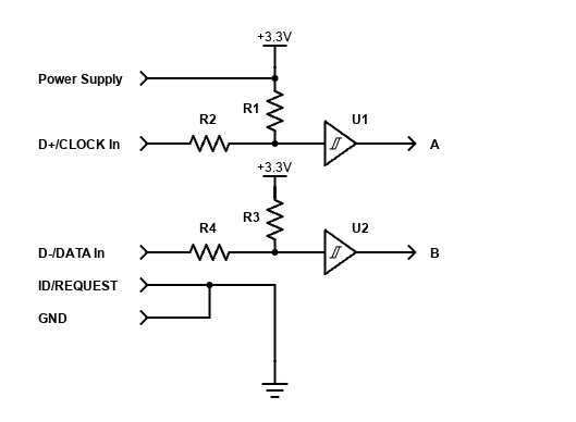
In both cases, the logical wiring is the same as for Mitutoyo SPC scales: CLOCK → A, DATA → B, and REQUEST held low. In the TouchDRO app, configure the axis as an SPC scale.
Chinese Capacitive Scales and Calipers (BIN6)
Many low-cost Chinese capacitive scales and digital calipers output a proprietary synchronous serial format commonly referred to as BIN6. TouchDRO Plus supports BIN6, but getting these scales working reliably is significantly more involved than wiring quadrature or SPC. For a deeper overview of the different families and quirks of these scales, see the Capacitive DRO Scales overview .
At a very basic level, BIN6 scales are usually wired like this:
- CLOCK → input A
- DATA → input B
- Ground → Ground
- Supply → the scale’s required voltage
In practice, there are several important complications:
- Non-standard supply voltages: some scales run around 1.5 V, others near 3 V, and many are not tolerant of higher voltages.
- Frame reference differences: some scales have a grounded frame; others have a “positive frame,” where the metal body is tied to the battery’s positive terminal. This can cause shorts or strange behavior if you mount them to a grounded machine and wire them like a normal grounded device.
- Poor documentation: pinouts and timing are rarely published, and similar-looking scales from different batches can behave differently internally.
Because of this, BIN6 integration should be treated as a small electronics project, not just a wiring task. At minimum, you should be comfortable:
- Measuring actual supply voltage before powering the scale
- Using an oscilloscope (strongly recommended) to verify idle levels, clock polarity, and signal integrity on CLOCK and DATA
- Dealing with grounding/frame issues and odd cable behavior
Once you have clean CLOCK and DATA signals referenced correctly to the scale ground and powered at the proper voltage, connect them to inputs A and B on the appropriate channel and configure that axis in the TouchDRO app as a BIN6 scale.
Wrapping Up
At this point you have the main pieces of a DIY TouchDRO build: an ESP32 module with the firmware loaded, a plan for how you will handle the scale inputs, and a sense of how the DIY kit and pre-assembled adapters differ. From here, the next steps are to mount your scales, connect them to the module or carrier board, and configure the app for your machine using the Quick Start Guide and the Initial Configuration instructions.
If you decide along the way that you would rather spend your shop time cutting metal than debugging electronics, you can always switch to a pre-assembled adapter and reuse the same scales and tablet. The TDK-40 DIY DRO Adapter Kit offers a partly built option, while the milling machine DRO and metal lathe DRO provide fully assembled TDA-4xx adapters. You can see all available adapters and accessories in the TouchDRO store. Either way, the end result is the same: a modern, tablet-based DRO with features normally reserved for high-end commercial systems, tailored to your machines and the way you like to work.