DIY DRO Adapter for iGaging Scales
TouchDRO adapter for iGaging linear DRO scales supports iGaging EZ-View DRO Plus, iGaging DigiMag Remote DRO and iGaging Absolute DRO Plus scales with Micro-USB cables. This is an upgraded version featuring faster position update rate, lower transmission lag and advanced digital signal processing for increased overall DRO performance and reliability.
This is an upgraded version of the TouchDRO adapter for iGaging Scales that uses a more powerful 32-bit processor and more advanced software. It supports up to four scale inputs, tachometer input, and touch probe/tool setter input.
The adapter is sold as a ready-to-use board with pre-installed Micro-USB Female connectors [USB Micro-B ]. It is built in an ISO-9001 factory using high-quality name-brand components and is inspected to meet stringent IPC-A-610 Class II standard. Each unit is carefully re-inspected, programmed and fully tested before shipping to ensure excellent performance and long-term reliability.
Features
- Four scale inputs via Micro-USB cables
- Tachometer input with a wide RPM range
- Touch probe/tool setter input
- Digital signal post-processing and jump detection*
- Powerful multi-core 32-bit processor
- Bluetooth connectivity for a clutter-free installation
- Ready for Lithium battery for scale power backup (battery not included)
Supported Scales
This DRO adapter supports the following iGaging scales without the need for additional soldering:
- iGaging EZ-View DRO Plus
- iGaging DigiMag (and the rebranded variants)
- iGaging Absolute DRO Plus
If your scale's display looks like one of the displays shown below (including color and markings), the scale will work with this TouchDRO adapter.

Older versions of the scales pictured above used Mini-USB cables. iGaging DigiMag, AccuRemote, and their unbranded versions use the same pinout and can be connected to the adapter via straight Mini-USB Female to Micro-USB Male adapter cables. iGaging Absolute DRO Plus scales use a different pinout and can be connected by directly soldering the wires to the board or using a set of Mini-USB breakout boards.
 and Mini-USB (right) connectors")
Other Supported Scales
In addition to the scales listed above, the adapter can work with the following scales and encoders:
- Shahe Remote DRO Readout Scales (5403-series)
- iGaging Absolute DRO Plus Scales Mini-USB version
- NPN rotary encoders (direct connection to the board)
- Glass and Magnetic DRO scales (via 5V-to-3.3V voltage reduction circuit)
Scale pinouts are described on the relevant scale details pages linked above.
Package Contents
TouchDRO Adapter for iGaging scales is a fully assembled, programmed and tested board sold either as a standalone board or as a kit with a 3D-printed plastic enclosure. To complete your DRO setup you will need to provide a set of compatible scales and a 5V Micro-USB power supply (common phone chargers work great in this application).
Adapter with 3D Printed Enclosure

- TouchDRO adapter for iGaging Scales
- 3D printed adapter enclosure with acrylic insert
- Stainless steel metric hardware (4 pcs. M3x20 screw; 4pcs. M3 nut)
Standalone Adapter Board
- TouchDRO adapter for iGaging Scales
Specifications
Capabilities
| Scale Inputs | 4 |
|---|---|
| Tachometer Input | Yes |
| Probe/Height Setter | Yes |
| Battery Backup | Yes (battery not included) |
| Power Supply | 5V DC, Micro-USB |
| Current Draw | Approx. 250 mA |
| Width | 2.5"/63.5mm |
| Length | 1.9"/48.3mm |
Recommended Operation Conditions
| Min | Typical | Max | |
|---|---|---|---|
| Tachometer Pulses/Second | 0.5 | 1,000 | 10,000 |
| Tachometer Accuracy | +/-1% | ||
| Position refresh rate | 1Hz (idle) | 8Hz (capacitive scales) 16Hz (glass/magnetic scales) |
|
| RPM refresh rate | 1Hz | 1Hz | |
| Probe/Limit switch trigger time | 1us | 20us (capacitive scales) 1us (glass/magnetic scales) |
100us (capacitive scales) |
Absolute Maximum Ratings
| Min | Typical | Max | |
|---|---|---|---|
| Supply Voltage* | 3.3V | 5.0V | 5.5V |
| Current Draw | 20mA | 120mA | 300mA |
| Scale Signal "High" Level | 2V | 3.0V | 3.3V |
| Scale Signal "Low" Level | 0V | 0.8V | 1.0V |
| Probe/Tach/Home signal "High" Level | 2.0V | 3.0V | 3.3V |
| Probe/Tach signal "Low" Level | 0V | 0.8V | 1.1V |
| Other inputs (Prog., JTAG, SPI) | 0V | 3.3V | 3.3V |
Mechanical Drawings

Documentation & Resources
Useful Resources
- iGaging EZ-View and DigiMag Scales
- iGaging Absolute DRO Scales
- Maximizing Capacitive Scale Reliability
- Common Problems with iGaging EZ-View Scales
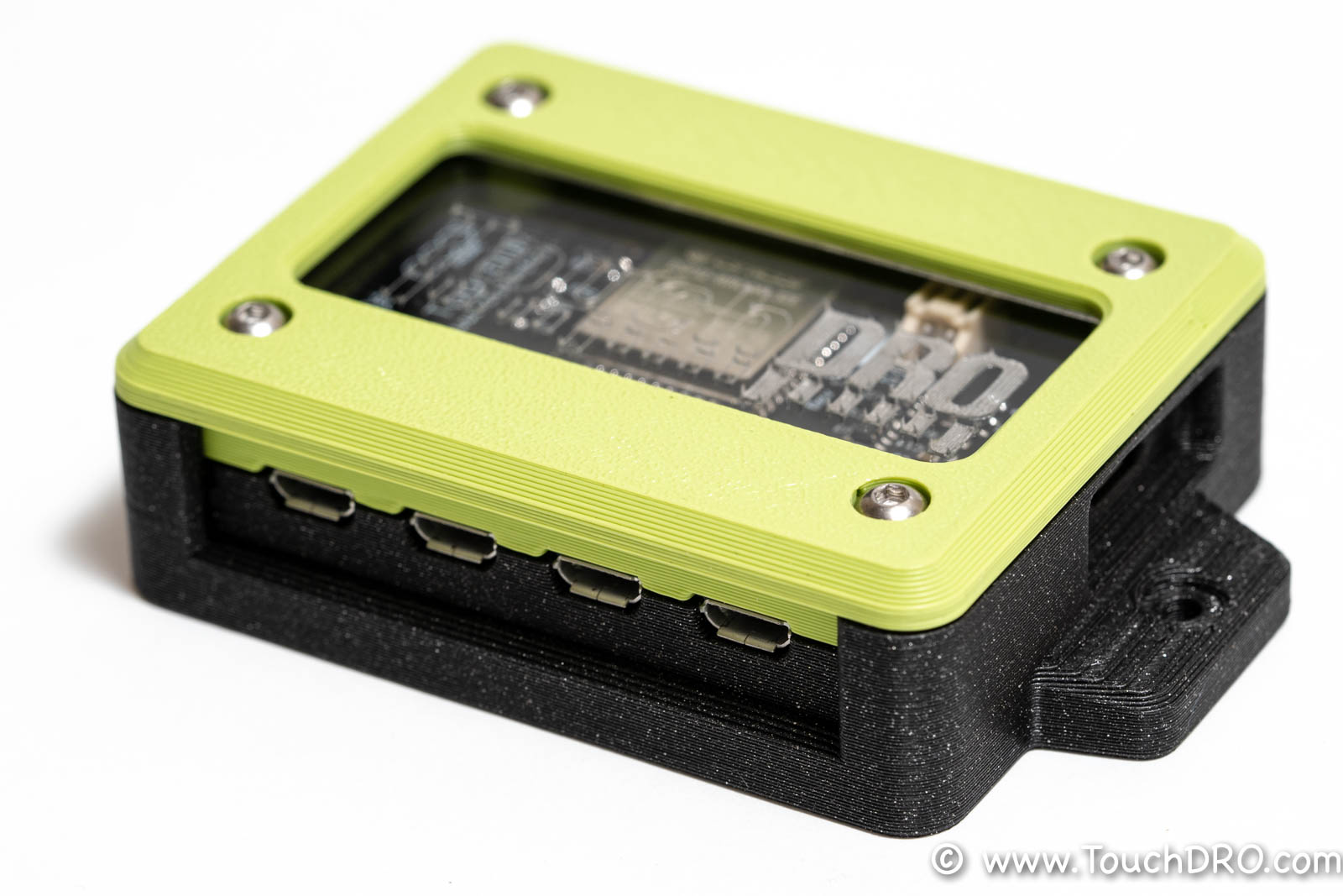
3D Printed Enclosure Assembly
Place the board into the enclosure with components facing up and power input aligned with the corresponding opening. The fit should be pretty close, so it is best to start at an angle and push the protruding part of the USB power sockets into the opening in the enclosure as shown in the picture. Then, lower the board into its position and gently press on it until it makes solid contact with the enclosure.

Insert the clear acrylic insert into the recess as shown in the photo below and place the lid on top of it. Ensure that the PCB mounting holes are aligned with the openings in the enclosure before inserting and tightening the four screws.

Port Functions

| Port | Description | 5V Tolerant | Note |
|---|---|---|---|
| X,Y,Z,W Inputs | Inputs for four linear axes | Yes | Pulled up to 3.3V |
| Tach | Tachometer input | Yes | Pulled up to 3.3V |
| Probe (unbuffered) | Tool height setter/touch probe input | Yes | Pulled up to 3.3V |
| PVR | Micro-USB Power supply input, 5V DC nominal | N/A | |
| 5V | 5V Power input/output | N/A | Connected in parallel with PWR |
| BAT | 1C LiPo battery connection | N/A | Optional, used to provide power backup to the scales |
Scale Inputs
This DRO adapter board comes with pre-installed USB Micro-B female connectors. Next to each connector, there is a set of holes for a 5-pin 0.1" header that breaks out Vcc, Ground, Clock and Data lines for the axis (pin functions are marked on the underside of the board).
Tachometer
Tachometer input is pulled up to 3V and works push-pull or open drain sensors that output 3.3V square wave.
Touch Probe
Inexpensive touch probes and tool height setters work similar to a simple electrical switch. Depending on the configuration, when the probe touches the workpiece, it either opens the circuit or closes it (normally-closed or normally-open, respectively). TouchDRO board supports (and automatically detects) both types.
The probe can be connected as follows: connect one side of the switch to Ground and the other to the probe pin. If the probe has a LED, it has to be reverse-biased (backwards), or the input won't work. To test this, connect the probe to Vcc and Ground. If the LED lights up (either when the probe is touching or not touching), reverse the leads.
Power Supply
This DRO adapter is designed to be powered by a common Micro-USB power supply such as phone charger. Alternatively, +5V and Ground pins are broken out next to the Micro-USB connector to allow the use of a panel-mounted power supply jack instead.
Battery
The optional 1-cell Lithium battery can be used to provide backup power in case the adapter's power supply is disconnected. It is designed to work with Lithium Polymer batteries that have built in over-discharge protection circuits and use 2-pin JST-PH (2.0mm pitch) connectors. The charging circuit is pre-set for 100mAh charge rate and can be used with any battery that is larger than 100 mAh. In practice, the battery capacity is constrained by the physical space available in the 3D printed enclosure, which is roughly 7mm x 30mm x 45mm.
Recommended batteries:

- Lithium Ion Polymer Battery - 3.7v 350mAh [Adafruit]
- Lithium Ion Polymer Battery Ideal For Feathers - 3.7V 400mAh [Adafruit]
- YDL 3.7V 650mAh 652540 Lipo Battery Rechargeable Lithium Polymer ion Battery Pack with JST Connector [Amazon]
- AKZYTUE 3.7V 550mAh 503041 Lipo Battery Rechargeable Lithium Polymer ion Battery Pack with JST Connector [Amazon]
Status LEDs
DRO scale adapter has three LEDs:
Green
Green LED is lit when the main processor is receiving power.
Blue
Blue LED indicates the current status. The codes are as follows:

Red
Red LED indicates the status of the battery charge monitor. When the battery is not connected, the state of the LED is irrelevant. Otherwise, the red LED is lit when the battery is charging and off when the battery is charged.
Connecting the Scales
- iGaging EZ-View DRO Plus, DigiMag "Remote DRO Display" and Absolute DRO Plus scales that come with Micro-USB cables can be plugged directly into the pre-installed USB Micro-B connectors
- iGaging DigiMag "Remote DRO Display" scales (and their rebranded versions such as Shars Digital Machine Scales and AccuRemote DRO scales) with Mini-USB connectors can be connected using a straight USB Mini-to-Micro adapter
- iGaging Absolute DRO Plus can be connected using a set of USB Mini-B breakout boards
- Glass/Magnetic Scales and other 5V quadrature encoders can be connected to the board using these instructions
IMPORTANT: Always disconnect the power supply and the battery when plugging or unplugging scales to avoid ESD damage to the scales or the adapter.
Grounding
Proper grounding is vital for reliable function of iGaging DRO scales. Unreliable ground connection or ground loop can lead to such issues as drifting position or random resets. In order to avoid ground loops, there should be a single reliable connection to the machine chassis. Ideally, scale frames should be isolated from the machine. If the cables are shielded, the shields should be tied to the ground only on one side and as close to the central grounding point as possible.
The board provides a number of easily accessible grounding points. Each port has a dedicated ground pin that is tied to the common ground pour. There are two ground pins next to each Micro-USB port and finally, the mounting holes are tied to the common ground as well.