
Wireless DRO Adapter for Glass/Magnetic Scales
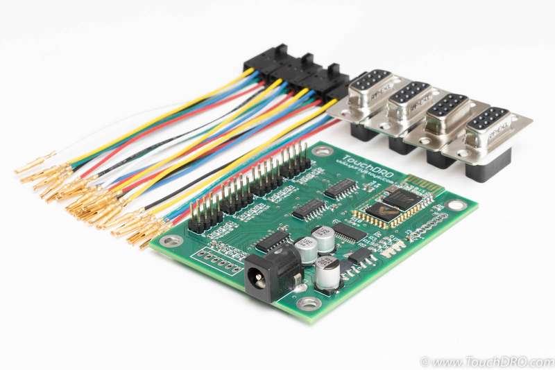
TouchDRO Adapter for Glass and Magnetic DRO scales includes a fully assembled adapter board and a set of harnesses with press-fit D-Sub 9 female connectors. The connectors can be customized to match the pinout of your particular scales without any additional soldering. The DRO adapter is optimized for demanding industrial applications. It supports most modern glass and magnetic scales and works with DRO scales and quadrature encoders that output either differential or single-ended signals.
Description
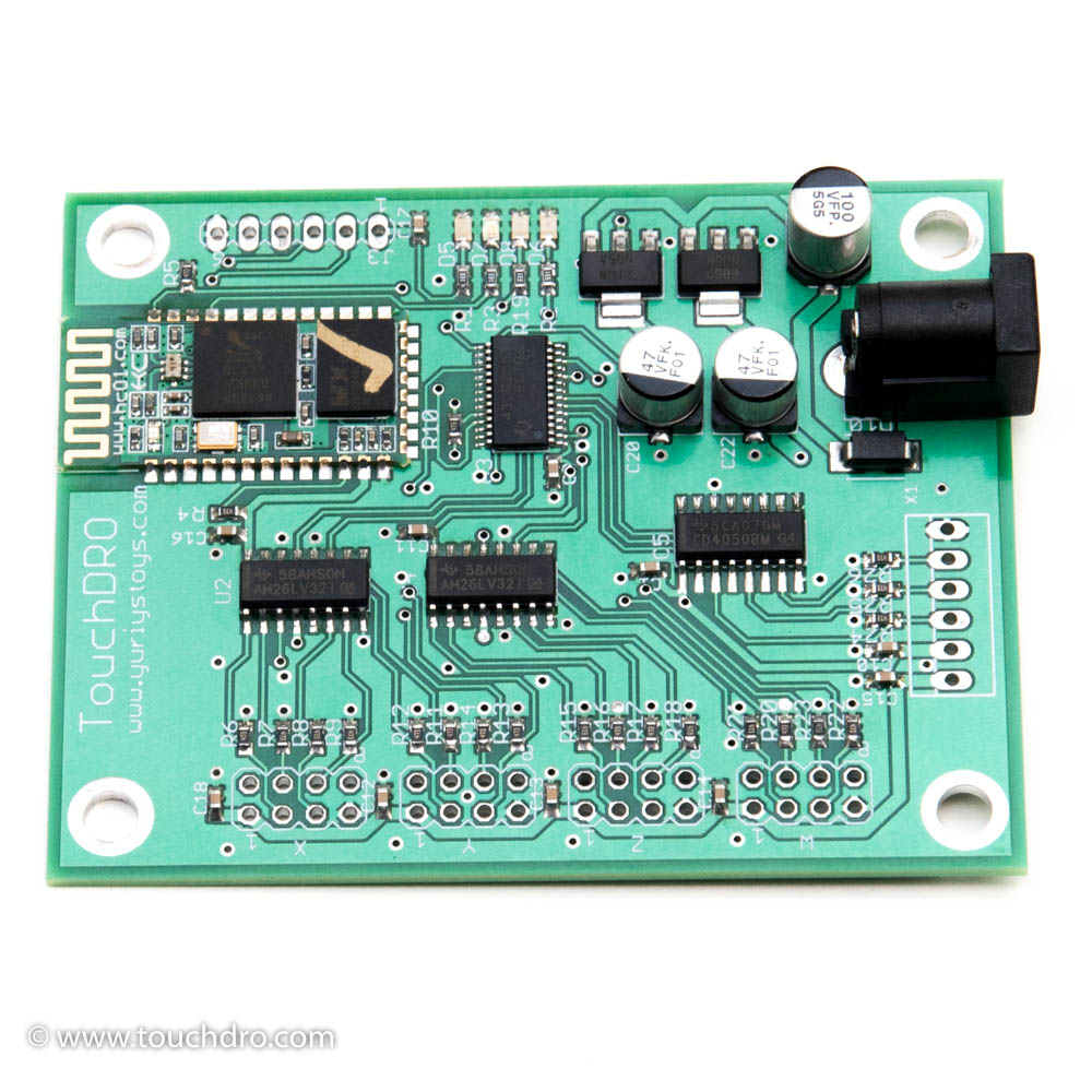
TouchDRO Quadrature DRO adapter kit works with Glass and Magnetic DRO scales that output either differential (RS-422) or single-sided (TTL) incremental quadrature signal. This includes most modern DRO scales on the market, including Ditron, Easson, Sino, some Acu-Rite models and many others. The circuit is engineered for industrial application and offers excelled noise immunity, reliability and repeatablity. To ensure long service life for the addapter and the scales, the circuit uses purpose-made RS-422 interface chips, name brand capacitors rated at at least double the expected input voltage, low dropout voltage regulator and high quality PCB.
Package Contents
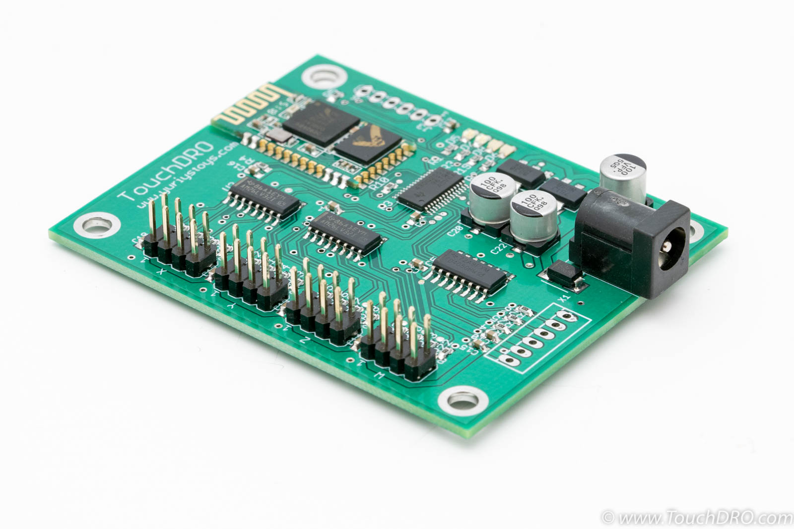
- Fully assembled and tested TouchDRO Adapter Board
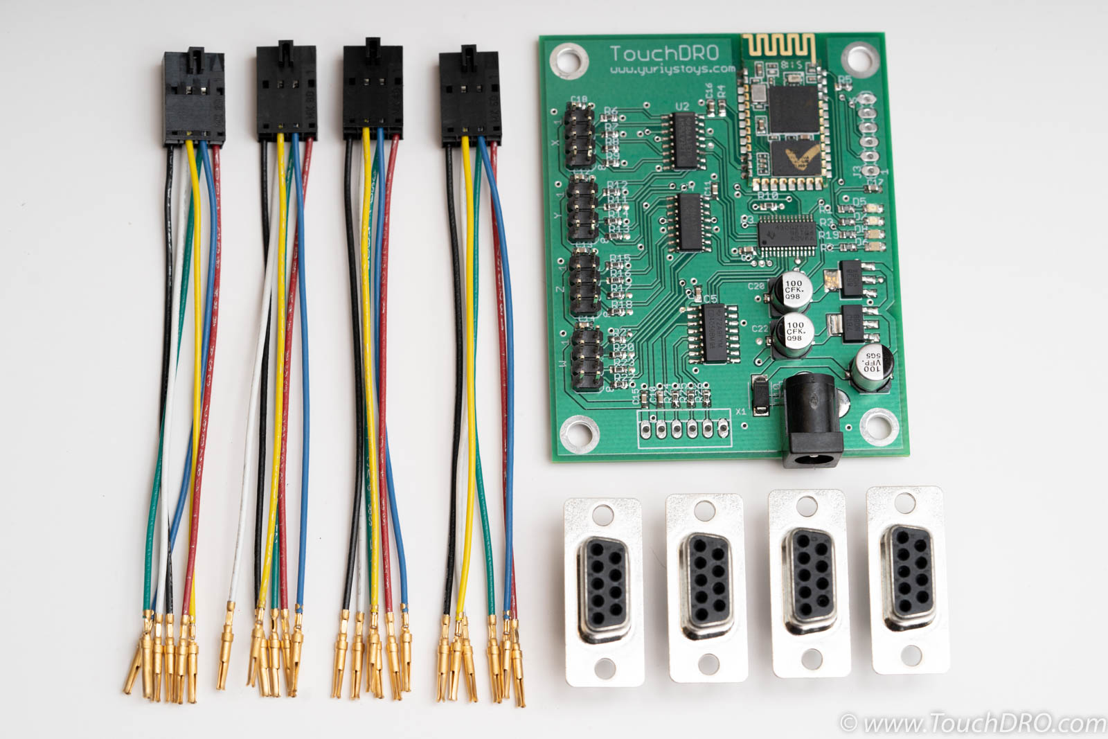
- Four press-fit D-Sub 9 Female Connectors
- Four pigtail cable aseemblies (2x4 header with six condictors)
All genuine TouchDRO adapters are assembled to stringent IPS-A-600/610 Class II or better standard and use quality name brand components for best reliability and durability. I personally inspect every board and run it through a full range of tests (scale connectivity, bluetooth, etc.) before shipping it to you.
Specifications
Features
| Scale Inputs | 4 |
|---|---|
| Angular Axis | Yes* |
| Tachometer Input | Yes |
| Probe/Height Setter | Yes |
| Power Supply | 7V DC - 12V DC |
| Current Draw | Approx. 50 mA |
| Width | 2.325" |
| Length | 2.9" |
Supported Scales
Controller supports most modern Glass and Magntic DRO scales that output TTL or RS-422 quadrature signal. This inludes:
- Ditron
- Eassong
- Sino
- Many others
Mechanical Drawings

Documentation
Port Functions

| Port | Description |
|---|---|
| X,Y,Z,W Inputs | Inputs for four linear axes. |
| Tach/Probe | Buffered tachometer and probe inputs. Directional tachomter requires optical encoder with quadrature input. For single pulse input use only "A" line |
| Power | Power supply input. Requires DC power source between 7V and 12V DC. Most optimal voltage is around 6V. Higher voltage will result in more heat around the voltage regulator; lower voltage might cause brownouts. |
Axis Input Pin Functions
Inputs for the scales are located along the left edge of the board, with first axis (X) on the top and last (W) at the bottom. Each connection uses a 2x4 pin header that has the following connections:
- Vcc - +5V supply for the scale
- A - primary input from A channel
- A' - complementary input from A channel
- B - primary input from B channel
- B' - complementary input from B channel
- Ground - 0V (connected to the chassis ground)
Inputs A' and B' are optional. If left unconnected, they will be pulled down to the ground and the readout will still work as expected. If the scales support differential output, it's recommended to use all four channels for better noise immunity. Otherwise the exposed pins of the unused wires need to be isolated to prevent them from shorting something out.
Tachometer
The board is setup to accept a directional tachometer that has either push-pull or line driver quadrature output. For directional input connect Vcc to either 3.3V or 5V (depending on your particular sensor), A and B output, and Ground. If B is not connected the tachometer will be non-directional.
Touch Probe
Inexpensive touch probes and tool height setters work similar to a simple electrical switch. Depending on the configuration, when the probe touches the workpiece it either opens the circuit, or closes it (normally-closed or normally-open, respectively). TouchDRO board supports (and automatically detects) both types.
The probe can be connected as follows: connect one side of the switch to Vcc (5v or 3.3V) and the other to the probe pin. If the probe has an LED, it has to be reverse-biased (backwards), or the input won't work. To test this, connect the probe to Vcc and Ground. If the LED lights up (either when the probe is touching, or not touching), reverse the leads.
Scale Connection
Step 1: Identify Pin Scale Function
Refer to your scale's documentation to determine the pin functions of the scale's D-Sub connector. Relevant pins are +5V, 0V, A and B; A' and B' are available only on scales with differential output.
Step 2: Assemble D-Sub Connectors
Press-fit the +5V, 0V, A and B, pins into the appropriate position on one of the female D-Sub connectors. To do so, hold the connector firmly in one hand and using a pair of small needle noze pliers, push the gold-plated pin into the hole until you feel a click and a positive stop.

- Red - +5V
- Black - 0V
- Green - A
- White - B
- Blue - A' [Optional]
- Yello - B' [Optional]
Plug in a scale into the X axis input (as shown in the next step), pair the board with TouchDRO app and confirm that the application is getting stable reading; assembled the rest of the connectors as needed.
Step 3: Plug The Cable Into The Adapter
Plug the cables into the adapter board with the tab facing invard.
Grounding
Proper grounding is very important for stable operation of the DRO unit. Although industrial-grade glass and magnetic scales aren't nearly as sensitive to EMF as their capacitive counterparts, electrical noise can still cause problems. The easiest way to reduce EMF issues is to ground the board to the machine's frame. Mounting holes on the board are tied to the ground fill, as are all of the ground pins.