DRO Adapter for Glass and Magnetic Scales V2
TouchDRO Adapter for Glass and Magnetic DRO scales is optimized for demanding industrial applications. It supports most modern glass and magnetic DRO scales, as well as incremental rotary encoders that output either differential or single-ended quadrature signal.
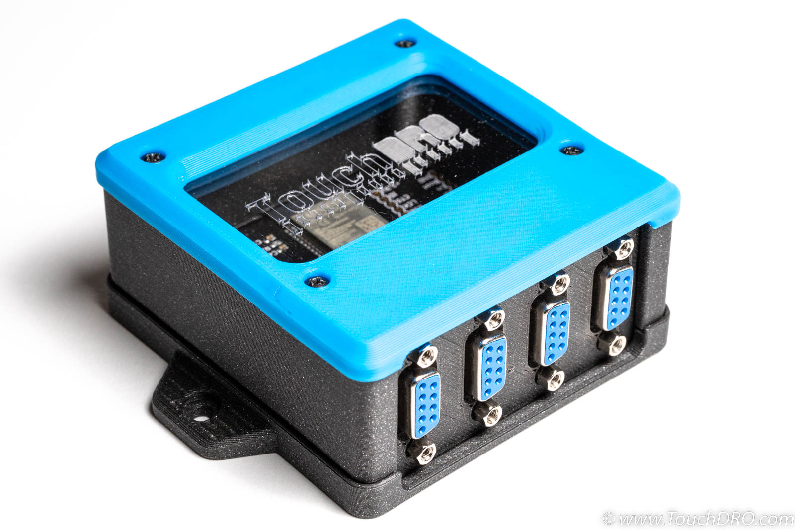
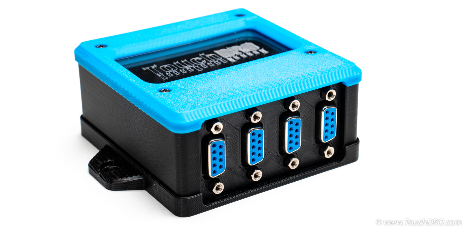
This is an updated version of the TouchDRO adapter for Glass and Magnetic Scales. It supports up to four scale inputs, tachometer input, touch probe/tool setter input, and up to four axis limit switches. The adapter can handle single-ended (TTL) and differential (RS-422) quadrature signals and supports most modern glass and magnetic DRO scales that output a 5V quadrature signal.
Each adapter is built from high-quality name-brand components to stringent IPC-A-610 Class II or better standard. I personally inspect, program, and test each and every unit before shipping to ensure excellent performance and long-term reliability.
Features
- Four scale inputs (differential and single-ended scales)
- Tachometer input with a wide RPM range
- Touch probe/tool setter input
- Limit switch inputs for each axis
- Powerful multi-core 32-bit processor for outstanding performance and reliability
- Bluetooth connectivity for a clutter-free installation
Purchase Options
4-axis DRO Kit with 3D Printed Enclosure
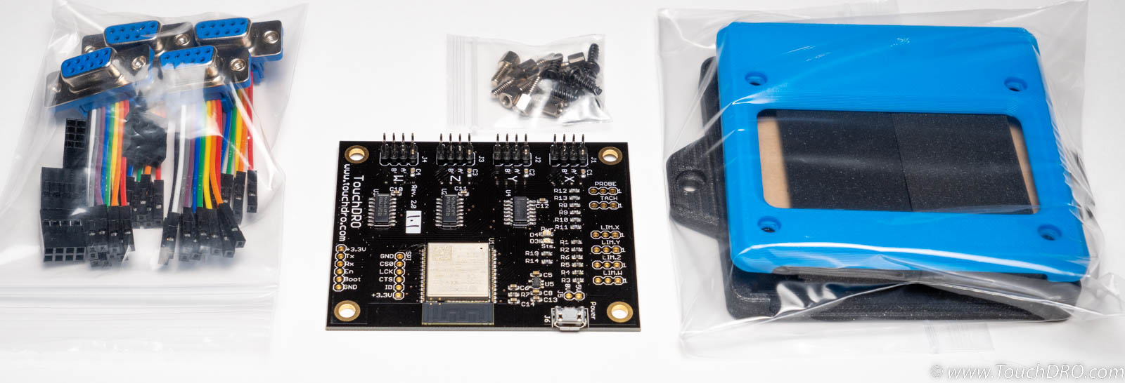
The "No Solder" kit comes with a set of press-fit D-Sub 9 pigtail connector assemblies, a lazer-cut acrylic enclosure kit and all of the necessary hardware. The contents are as follows:
- TouchDRO Glass scale Adapter mainboard
- Press-fit (no soldering required) D-Sub connector kit:
- Four press-fit panel mounted Dsub-9 female connector housings
- Four 4x2 Molex connector housings
- 24 pre-crimped leads (6 leads per axis)
- 4-axis stainless steel hardware kit
- 3D-Printed Enclosure (unassembled)
Fully Asembled TouchDRO Adapter
Fully assembled adapter comes pre-configured for scales from some popular manufacturers and is ready for use.
You will need to provide a compatible Micro-USB power supply, such as an phone charger.
Before placing an order, please confirm the pinout of your scales in the documentation provided by the supplier.
Current pinout options are as follows:
Option A - Electronica/EMS
This configuration is for Electronica/EMS scales sold by DRO Pros in the USA. If you are planning to purchase your scales from a different supplier, please confirm that the scales use the same pinout.
| Pin | 1 | 2 | 3 | 4 | 5 | 6 | 7 | 8 | 9 |
|---|---|---|---|---|---|---|---|---|---|
| RS-422 w/Reference | +Z | -Z | Vcc/5V | Shield | OV/Gnd | +A | -A | -B | +B |
Option B - Ditron/Sino/Aikron
Scales from Ditron, Sino and Aikron use identical pinout. Depending on the scale model, some pins might be left disconnected.
| Pin | 1 | 2 | 3 | 4 | 5 | 6 | 7 | 8 | 9 |
|---|---|---|---|---|---|---|---|---|---|
| RS-422 w/Reference | A'/A- | 0V | B'/B- | Shield/Ground | R'/Z' | A | +5V | B | R/Z |
| RS-422 w/o Reference | A'/A- | 0V | B'/B- | Shield/Ground | A | +5V | B | ||
| TTL w/Reference | 0V | Shield/Ground | A | +5V | B | R/Z | |||
| TTL w/o Reference | 0V | Shield/Ground | A | +5V | B |
Option C - Generic Chinese Scales
This is one of the common DB9 pin configurations used by various Chinese DRO scale resellers. In the USA, this includes Vevor and some other resellers on Amazon and eBay.
| Pin | 1 | 2 | 3 | 4 | 5 | 6 | 7 | 8 | 9 |
|---|---|---|---|---|---|---|---|---|---|
| TTL w/Reference | 0V | A | 5V | B | R1/Z |
Option D - Generic Chinese Scales
This is another common DB9 pin configurations used by various Chinese DRO scale resellers.
| Pin | 1 | 2 | 3 | 4 | 5 | 6 | 7 | 8 | 9 |
|---|---|---|---|---|---|---|---|---|---|
| TTL w/ Reference | +5 | 0V | A | B | R/Z/Abs | ||||
| TTL w/o Reference | +5 | 0V | A | B |
Custom Pinout
If your scales are not covered by one of the above configurations, the adapter can be configured with a custom pinout. Contact us after ordering and provide the documentation for your scales showing the connector pin assignment.
Specifications
Supported Scales
This TouchDRO adapter supports a vast majority of Glass and Magnetic DRO scales on the market that output 5-Volt quadrature signal. This includes virtually all Chinese DRO scales from brands like Easson, Ditron, Sino, and many others. The majority of modern scales from well known western DRO brands are supported, as long as they provide 5V quadrature output. This includes most EMS (Electronica Mechatronic Systems) magnetic scales, many Acu-Rite scales, etc.
To determine if your scales are supported, look for the pinout diagram or pin descriptions in the scale's manual or spec sheet.
Supported
- Scales that have pins labeled +5V, 0V (or Ground), "A" and "B" output "single-ended" quadrature signal.
- Scales that have are pins marked A' and B' (or alike) output "differential" signal.
Not Supported
- Scales that have pins labeled +1V, V1+/V1-, or V2+/V2- (or similar) output sine wave and need a priprietary interpolation circuit
- Scales that have pins labeled -5V, -7V or -24V require negative power supply and are not supported directly
- Scales that have pins labeled "Data", "Clock", "En", etc. are not compatible
Rotary Encoders
The adapter directly supports 5V incremental rotary encoders with push-pull or "open drain" (also called "open collector" or "NPN") output. Encoders with PNP, or "open sink" otput are not supported.
Capabilities
| Scale Inputs | 4 |
|---|---|
| Angular Axis | Yes* |
| Tachometer Input | Yes |
| Probe/Height Setter | Yes |
| Axis Limit Switches | 4 |
| Power Supply | 5V DC, Micro-USB |
| Current Draw | Approx. 250 mA |
| Width | 3.1"/78.7mm |
| Length | 2.5"/63.5mm |
Recommended Operation Conditions
| Min | Typical | Max | |
|---|---|---|---|
| Axis Input Edges/Second | 100,000 (100KHz) | 250,000 (250KHz) | |
| Tachometer Pulses/Second | 0.5 | 1,000 | 10,000 |
| Position refresh rate | 1Hz (idle) | 25Hz (active) | |
| RPM refresh rate | 1Hz | 1Hz | |
| Probe/Limit switch trigger time | 0.2s | 20us | 100us |
Absolute Maximum Ratings
| Min | Typical | Max | |
|---|---|---|---|
| Supply Voltage* | 3.3V | 5.0V | 5.5V |
| Current Draw | 20mA | 120mA | 300mA |
| Scale Signal "High" Level | 2V | 5.0V | 5.8V |
| Scale Signal "Low" Level | 0V | 0V | 0.8V |
| Probe/Tach/Home signal "High" Level | 3.9V | 5V | 5.5V |
| Probe/Tach/Home signal "Low" Level | 0V | 0V | 1.1V |
| Other inputs (Prog., JTAG, SPI) | 0V | 3.3V | 3.6V |
*Min. supply voltage requirement might be higher for some scales. 3.3V is the lowest level at which the main processor will operate.
Mechanical Dimensions

Documentation & Resources
Useful Resources
- Glass/Magnetic Scale Adapter Quick Start Guide
- Overview of Glass DRO Scales
- Overview of Magnetic DRO Scales
- Identifying Unknown Scale Pinouts
- TouchDRO Initial Configuration
- DRO DRO Calibration
Port Functions

| Port | Description | 5V-Tolerant | Note |
|---|---|---|---|
| X,Y,Z,W | Inputs for four linear axes | Yes | Pulled up to 3.3V via weak internal pull-ups |
| Tach. | Tachometer input | Yes | Pulled up to 5V |
| Probe | Touch probe input | Yes | Pulled up to 5V |
| LIM.X-LIM.W | Axis limit switch inputs | Yes | Pulled up to 5V |
| J6 | 5V Power input | N/A | Micro-USB input jack |
| J5 | 5V Power input/output | N/A | Connected in parallel to J6 |
| PROG | ESP32 Programming Port | No | Used to re-program ESP32 |
| J7 | Diagnostics switch | No | Disabled in production firmware |
| J8 | SPI Port | No | Not used; for future expansion |
Axis Input Pin Functions
Inputs for the scales are located along the left edge of the board, with the first axis (X) on the top and last (W) at the bottom. Each scale input uses a 2x4 pin header that has the following connections:
- Vcc - +5V supply for the scale
- A - primary input from A channel
- A' - complementary input from A channel
- B - primary input from B channel
- B' - complementary input from B channel
- Ground - 0V (connected to the chassis ground)
Inputs A' and B' are optional. If left unconnected, the readout will still work as expected. If the scales support differential output, it's recommended to connect the differential channels for better noise immunity when using long cable runs (over 5 meters).
Tachometer
The adapter uses a pulse-counter tachometer input that can work with sensors that output a 5V "push/pull" signal or "open drain" (also called "open collector" or "NPN") sensors. The firmware can calculate the RPM with pulse frequency as low as 0.5Hz and as high as 10KHz, but for best accuracy and reliability, it's recommended to use encoder disks that produce pulse frequency between 10Hz and 1KHz during normal operation.
Touch Probe/Tool Setter Input
Probe/Tool Setter input is a 5V-tolerant binary (on/off) input that can be used with either normally-open or normally-closed touch probes and tool height setters. The switch type is detected at boot time.
Axis Home Switch Inputs
Each of the four axis inputs has a corresponding limit switch input that can be used to manually home the machine. When used with repeatable switches, TouchDRO can simulate the functionality of high-end DRO scales that have "origin" marks or "home" areas.
The pins are pulled to 5V using large value resistors and should be used with normally-open switches. When a "limit" pin is pulled to the ground, the readout for the given axis is zeroed out in the firmware.
Assembly and Setup
Identify Scale Connector Pinout
Refer to your scale's documentation to determine the pin functions of the scale's D-Sub connector. Relevant pins are +5V, 0V, A, and B; A' and B' are available only on scales with differential output.
Unbranded Chinese scales often come with the wrong documentation or lack it altogether. Fortunately, most of these scales are based on the same circuit (with minor variations) and the pinout can be relatively easily reverse-engineered using instructions described in "How to Find the Pinout of an Unknown DRO Scale".
Connect the Scales
To operate correctly each scale needs to have +5V, Ground and at least A and B lines connected. Lines A' and B' (on differential scales) provide better noise immunity but are otherwise optional.
"No Soldering" Kit
Detailed assembly instructions for the Deluxe Kit can be found on the Glass/Magnetic Scale Adapter Quick Start page.
Standard Kit
The standard kit comes with panel-mounted female D-Sub 9 connectors and a set of Dupont jumper wires. To assemble the harnesses you will need to cut the jumper wires that you can use to make four sets of leads. The process is as follows:
- Separate the ribbon cable into sections with four or six wires (four for single-ended scales, six for differential).
- Cut each section in half and trim to the desired length. It's best to leave a bit of slack, so the cables are not under strain while mounted in the enclosure.
- Strip and tin the cut ends
- Solder the leads to the appropriate pins
- Using the diagram from the "Input Pin Functions", connect the female ends of the Dupont leads to the TouchDRO adapter.
Since the TouchDRO adapter will be likely subjected to vibration, it's recommended to hot-glue the connectors to the board to prevent them from coming loose during use.
Mount the Adapter into An Enclosure
TouchDRO adapters require a non-metallic enclosure in order for the Bluetooth signal to reach the tablet. Since the electronics don't produce much heat, there are no special material or size requirements for the enclosure, as long as the board fits it.
A standard 115mm x 90mm x 55mm ABS enclosure with clear top works very well for this adapter and can be purchased for under $10 (USD) from eBay and many other online retailers.
Press-fit the +5V, 0V, A and B, pins into the appropriate position on one of the female D-Sub connectors. To do so, hold the connector firmly in one hand and using a pair of small needle noze pliers, push the gold-plated pin into the hole until you feel a click and a positive stop.
Grounding
Proper grounding is very important for stable operation of the DRO unit. Although industrial-grade glass and magnetic scales aren't nearly as sensitive to EMF as their capacitive counterparts, electrical noise can still cause problems. The easiest way to reduce EMF issues is to ground the board to the machine's frame. Mounting holes on the board are tied to the ground fill, as are all of the ground pins.