DIY Adapter for Shahe/iGaging Scales
The 3V Shahe and iGaging scales work comfortably with 3.3V power supply and don't have any special input requirements. This means that the adapter is relatively simple and easy to build since it requires only a few additional parts on top of the base control circuit.
Since these scales use very little current, it's easy to power them from two 1.5V batteries instead of using the main 3.3V supply. A set of AA cells will power these scales for months or even years. This offers two advantages. First of all, the scales will not lose power when the adapter is powered off and will, therefore, behave more like absolute encoders. Second, separate power supply eliminates a ground loop in the setup and might help improve scale stability.
Required Tools and Supplies
Electrical TapeIn addition to the tools and supplies needed to build the base control circuit, you will need a small amount of electrical tape or a piece of heat-shrink tubing around 5mm in diameter and 20mm in length. It will be used to make a splitter cable described below.
Parts List
| Part | Qty | Price Each | Note |
|---|---|---|---|
| TI Value Line MSP430 Launchpad | 1 | $10-$12 | |
| MSP430G2553 | 1 | $3-$5 | |
| HC-05 Bluetooth Transceiver Module | 1 | $5-$7 | |
| Mini-B or Micro-B USB Breakout Board* | 4 | $1.50-$3.00 | 1 per scale |
| Dupont Jumper Wire (Female-to-Female) | 20 | $3-$5 | 4 or 5 per scale |
| 0.1uF Ceramic Axial Capacitor | 4 | $0.10-$1.0 | 1 per scale |
| 2x AA Battery Holder (optional) | 1 | $2-$5 | Optional |
| Schottky Diode | 2 | $0.25-$1 | Optional |
* It's best to buy USB breakout boards that include 0.1" headers in the kit or preinstalled; otherwise, you will need to obtain the headers separately.
Please note, the parts list above includes all of the needed components, including those covered in the base control circuit.
Mini/Micro-B Breakout Boards
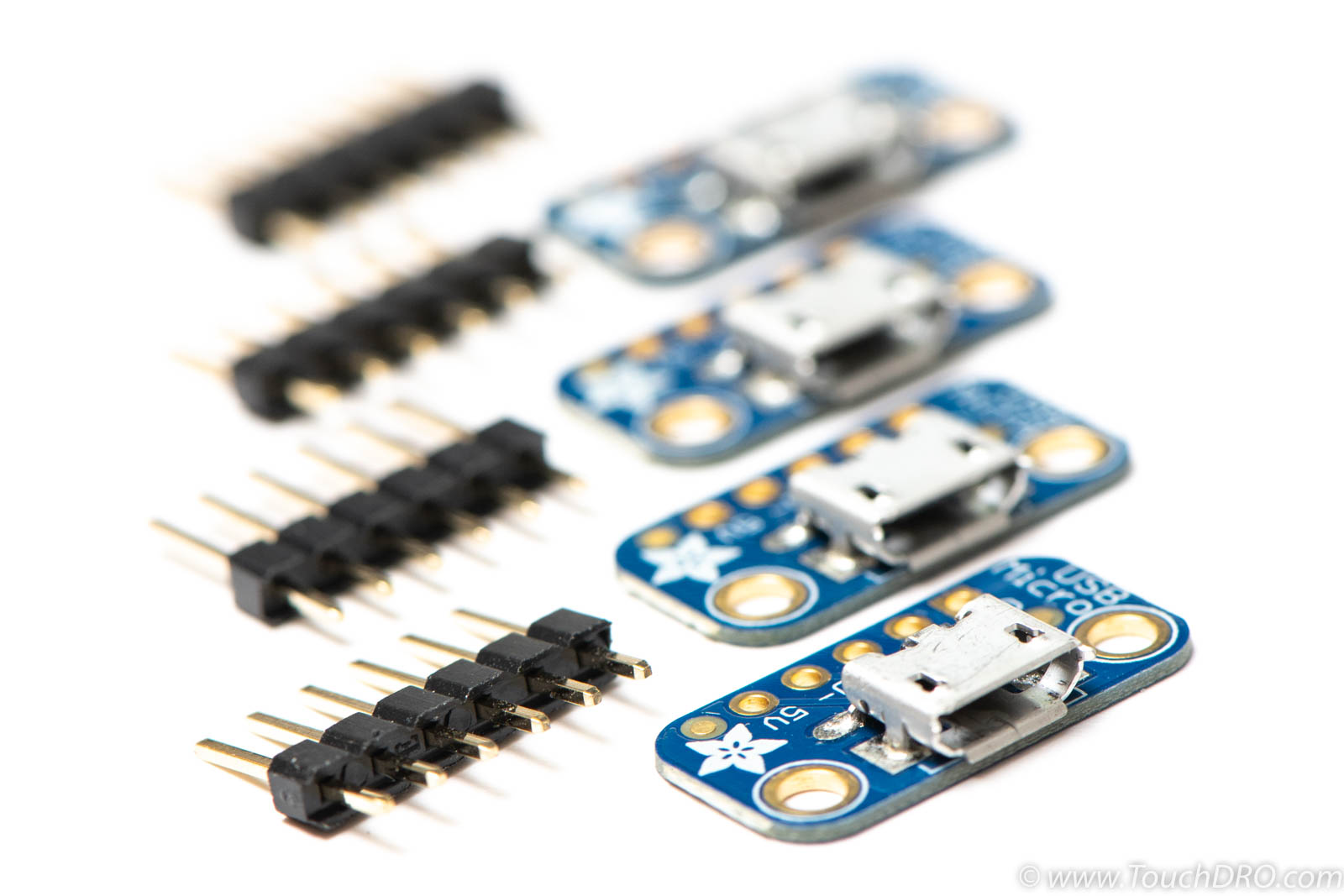
Depending on the USB connector type used by your scales, you will need to get the correct type of USB breakout boards. The boards are available from eBay, Amazon and many other online retailers. The price per unit is between $1 and $3 plus shipping. There are no big differences in quality between different brands, so you shouldn't spend more than $10 for a set, including shipping. Look for sellers that include 5-pin headers in the kit for each board.
DuPont Wires
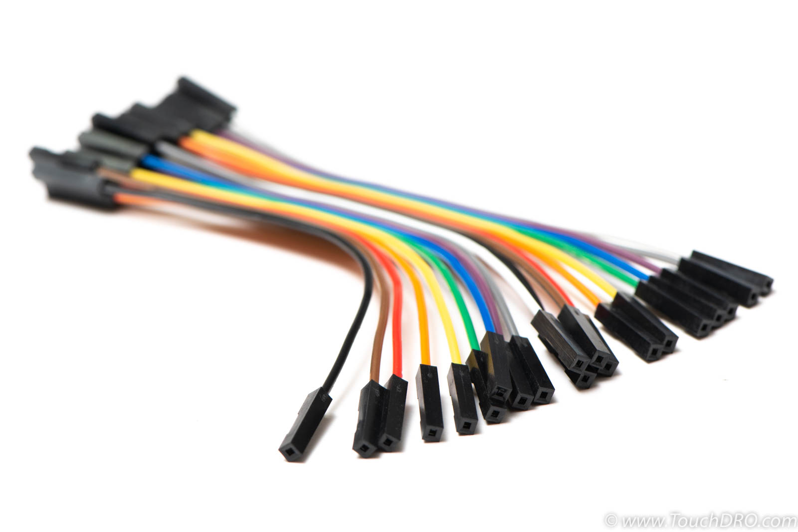
Jumper DuPont wires are connecting wires with pre-crimped 1-pin male or female connectors on both ends. They are commonly used in breadboard prototyping but make good enough connection for a permanent DRO setup. For this build, you will need four or five female-to-female wires per scale input. Since most sellers sell them in increments of 20 (as a ribbon cable), you will need one set, preferably 5cm or 10cm long; longer wires are harder to arrange and create extra opportunities for noise and interference.
Ceramic Capacitors
iGaging and Shahe scales benefit greatly from bypass capacitors in the 0.1uF range. These capacitors are very common and can be purchased for about $0.1/peace from any electronic component supplier, eBay, etc.
Battery Holder
As mentioned above, it's possible to power the scales from two 1.5V batteries. To do so, you will need a battery holder that can hold two cells. At least AA cells are recommended, but C or D cell will last much longer.

Schottky Diodes
Rather than powering the scales from the battery pack full time, you might want to provide battery backup that kicks in only when the Launchpad is powered off. Connecting the batteries in parallel with the 3.3V voltage regulator will result in them being charged and [likely] exploding. Likewise, you wouldn't want the batteries to be drained by powering the whole adapter circuit, you will need two Schottky diodes. Schottky diodes differ from regular diodes in that they have low forward voltage dropout. For the purposes of this circuit, any Schottky diode will do the job, since high current or voltage is not a concern.
Build Instructions
All versions of TouchDRO firmware are using the same MSP430 microcontroller pin functions that are explained on the "MSP430 Pin Functions" page. You will need to refer to this page throughout the build.
Step 1: Build and Test Base Control Circuit
Build and test the base control circuit following these build instructions.
Step 2: Make Wire Harnesses
Each scale requires a Vcc and Ground connection. Since MSP430 Launchpad doesn't have enough broken out pins to connect to each scale, you will need to make two cable harnesses as shown below. Using this style of a harness is better than daisy-chaining the scales since it doesn't create unnecessary ground loops that can pick up electrical noise.
The harness will need to have as many branches as you have scales. For the sake of this build, let's assume that you have four scales. Depending on whether or not you want to use a battery pack to power the scales or provide battery backup, the harness will need to be configured differently (more on that later).

Regardless of the type, to make a reliable harness you will want to twist the wires together, apply some flux (if available) and solder them making sure that all wire strands are covered with solder.

No Battery Power
Cut off the connector from one end of 10 DuPont wires, strip about 10mm of insulation and solder the wires together identically to the ground harness show above.
Battery Power for Scales
To power the scales from a battery, you will need to replace one of the legs of the positive wire harness with a battery holder. Additionally, the negative side of the battery will need to be connected to the Launchpad to provide a common ground. The finished harness should look similar to the picture below.

Battery Backup
The negative side of the harness for the battery backup is identical to the one used for battery power; positive side needs to have a few changes.
Start by cutting off connectors from five wires and strip about 10mm of insulation and solder them to the negative side of the diodes (the side with the band). The remaining wire needs to be soldered to the positive side of one of the diodes. The other diode should be soldered to the positive side of the battery holder. The negative side of the battery holder will need to be connected to the Launchpad to provide common ground reference.

If you have some heat shrink tubing, use it to insulate the solder joints, making sure to insulate the positive sides of the diodes so they don't touch.

Step 3: Prepare the Breakout Boards

Solder the 5-pin male header to the USB breakout boards. Soldering all of the pins at once can be a bit fiddly. It's easier to solder one pin, straighten the header and then solder the remaining four pins.
Step 4: Add Bypass Capacitors
Bypass capacitors help to clean up the power supply for the scales by providing a bypass path for short voltage spikes. They should be installed as close to the scale's encoder as possible. Ideally, they should be added to the encoder PCB; if you are uncomfortable with modifying the scales, another option is to add capacitors to the breakout boards.
Modifying the Scales
Idelly, bypass capacitors should be located as close to the relavant circuit component as possible. In this case the idal location is righ on the encoder PCB in the scale rading head. Conveniently, iGaging EZ-View DRO Plus, iGaging DigiMag, and other related 21-bit scales' encoder PCBs have test points to which a capacitor can be soldered. One side of the capacitor should be soldered to the "Vdd" pad, and the other to the ground, as shown in the pictures below.


Breakout Board Mounted
Refer to the details page for your scales to find out which pins on the breakout board are for Vcc and Ground. The pages are linked from the Compatible Capacitive DRO Scales page.

- Prepare the capacitors by cutting their leads so the total length is about 1.5 times the distance between the pins
- Bend the leads inwards slightly
- Soder one lead to the Vcc pin on the back side of the board; if available use some flux to dip the lead before soldering
- Carefully bend the leads more until the other lead makes contact with the Ground pin and solder it there
- Inspect the final assembly to make sure you did not create any solder bridges
Step 5: Connect The Breakout Boards
Refer to the details page for your scales (same as the step above) to identify the pin function mapping for your scales.
Ground
Ground pins of every scale need to be connected to one of the ground pins on the MSP430 board regardless of whether or not you are using a battery.
Vcc
Vcc, or positive voltage, pins of the scales need to be connected to the appropriate power supply. If you are using a battery to power the scales and followed the instruction in the section above, the battery holder is already connected to the harness. When using a battery backup or no batteries at all, Vcc harness needs to be connected to the LaunchPad's 3.3V supply.
Data and Clock Pins
Once the power supply lines are connected, connect the Clock and Data lines as described on the scale information page.
Step 6: Bench-Test the Adapter
Before other variables are introduced, ensure that the adapter is working as expected by testing each scale input with a known good scale. The suggested process is as follows:
- Power up the TouchDRO adapter from a AC-DC power adapter or a battery bank
- Connect the TouchDRO app to the adapter and ensure that it stays connected for at least 30 seconds and reads 0s for all inputs
- Plug a scale into one of the breakout boards
- Reset the adapter (press the reset button or cycle the power); wait for the adapter to finish the protocol detection routine (the status LED will start blinking one per second)
- Reconnect the app if needed (only if the adapter was power cycled)
- Move the scale slowly and ensure that the DRO output works correctly
- Repeat steps 3-6 for each input
Step 7: Finalize the Build
Once the adapter passes the test, it's a good idea to secure the connectors so they don't fall out from vibration. A good way to do so is to put a dab of hot glue on each connector making sure not to cover any surface mount parts. This will provide a secure connection but can be undone at a future point if needed. Alternatively, you can remove the plastic from the connectors and solder them to the pins.
Troubleshooting
Assuming that the adapter worked before the breakout board was connected, there are only a handful of things that might've gone wrong.
The Board No Longer Powers Up
This is most likely caused by a short between the Vcc and Ground pins on one of the breakout boards.
- Unplug all of the boards.
- Inspect the solder joints for any bridges.
- Using an ohm meter, confirm that there is no bridge between any of the adjacent pins
- Confirm that the adapter powers up. If it doesn't, measure the supply voltage to ensure that it's at 3.3V. If you get no reading, the voltage regulator circuit might be blown and the Launchpad will need to be replaced or repaired.
- Plug in one board at the time. If the adapter stops working, unplug it immediately and investigate the source of the short.
TouchDRO Displays "1"
This is caused by a bridge between Data line and either Clock line or Vcc line. Follow the steps in the above section to troubleshoot.
TouchDRO Reads "0" With the Scale Plugged In
This happens when TouchDRO adapter is not getting a reading from the scale or the scale is sending all 0s.
- Move the scale to ensure that the scale isn't indeed reading 0
- Check for shorts between Data or Clock lines and Ground following steps above
- Using a multimeter, check continuity between breakout board pins and their Launchpad counterparts
- Ensure that the scale pins are wired correctly
- Using a Voltmeter, check that the scale is receiving 3.3V from the board
- Check that the scale is functional when plugged into its own display
Scale Reading Jumps Erratically
This can be caused by a loose scale connection, or more likely, by Clock and Data lines being reversed.
- Check the connection using a multimeter
- Make sure Clock and Data lines are wired correctly
Conclusion
As you can see, building a TouchDRO adapter for iGaging and Shahe scales based on TI MSP430 Launchpad is relatively easy. Following the steps on this page should yield a working DRO adapter that will handle the noise in an average garage shop well. If your environment is exceptionally noisy or the resulting setup acts erratically when installed on the machine, there are some additional steps you can take to avoid many of the common stability problems.