How to Build the TouchDRO Control Circuit
All do-it-yourself versions of MSP430 TouchDRO adapter are built from the same foundation circuit. The circuit consists of MSP430G2553 microcontroller, HC-05 Bluetooth transceiver and a 3.3V voltage regulator. It can be easily built from individual components but a better option is to use the Texas Instruments Value Line MSP430 Launchpad development kit. The Launchpad includes the microcontroller and all of the necessary support electronics. The only other component needed to finish the base control circuit is a BlueTooth transceiver.
Parts List
| Qty | Note | Price Each |
|---|---|---|
| MSP430G2553* Microcontroller | 1 | $0-$5 |
| TI Value Line MSP430 Launchpad | 1 | $10-$12 |
| HC-05 Bluetooth Transceiver Module | 1 | $5-$7 |
| Dupont Jumper Wire (Female-to-Female) | 4 | $1-$3 |
*At the time of this writing TI Value Line MSP430 Launchpad includes an MSP430G2553 microcontroller
MSP430G2553 Microcontroller
The MSP430 microcontroller is the "brain" of the TouchDRO adapter that runs custom firmware to do all of the scale data processing. There are many different models of this IC with different built-in peripherals. TouchDRO firmware is written for MSP430G2553 and will not run correctly on a different MSP430 microcontroller family.
The Value Line MSP430 Launchpad kit includes MSP430G2553 chip, so you will not need to purchase it separately unless (it was missing or damaged. Since MSP430 is a very popular microcontroller, most reputable electronic component suppliers carry it. The price in the USA is around $3 for a single chip; in other countries, it might be higher.
MSP430 comes in many different packages. Since we are discussing a DIY build, the DIP20 version is the best choice. Otherwise, you will need to use an SMT carrier board and perform some fine-pitch soldering.
MSP430 Launchpad

Value Line MSP430 Launchpad is a development kit manufactured and sold by Texas Instruments. It consists of a small board that contains an in-circuit programmer/debugger, power supply, some buttons and status LEDs, and a DIP20 socket for MSP430 microcontroller with the pins broken out to 0.1" header.
The current version of the Value Line MSP430 Launchpad comes with MSP430G2553 microcontroller and sells for $10 on TI's website. In other parts of the world, you might need to buy the kit from a reseller and the price will likely be higher.
There are several versions of the TI Launchpad kit in general, and at least one that uses a larger and more advanced MSP430 microcontroller. For this build, you want the Value Line MSP430 version that comes with a DIP20 socket, not a large surface-mounted part.
HC-05 BlueTooth Module
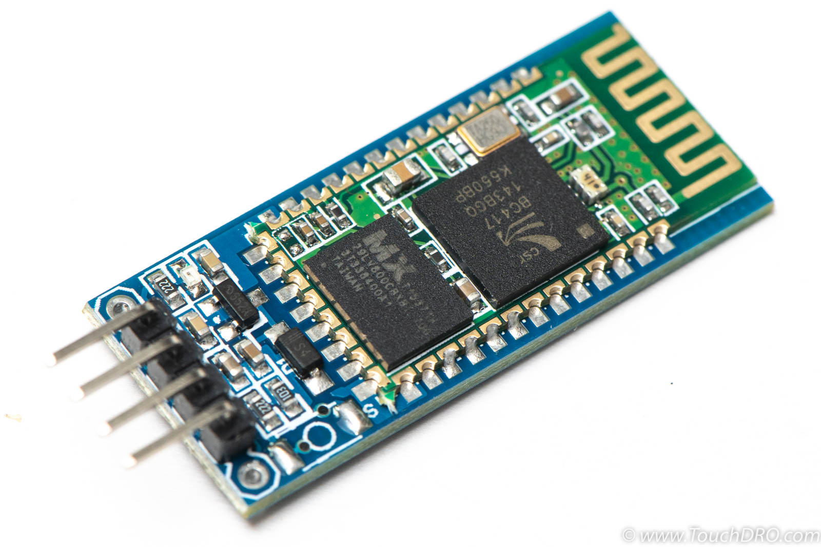
HC-05 BlueTooth modules were developed by Huicheng Information Technology Co., Ltd. in China and are now manufactured and sold by several different companies. There is no reliable way to tell the original modules from the copies, but both appear to work equally well.
For the TouchDRO adapter build it's better to get a module mounted to a carrier board (often called JY-MCU) that conveniently breakout out the necessary pins to a 4-pin header.
The module can be purchased from eBay and many other online retailers. Many sellers sell the module with a pre-installed 4-pin header and a set of jumper cables in the kit. The average street price in the USA is between $5-$7, including shipping.
DuPont Jumper Wires
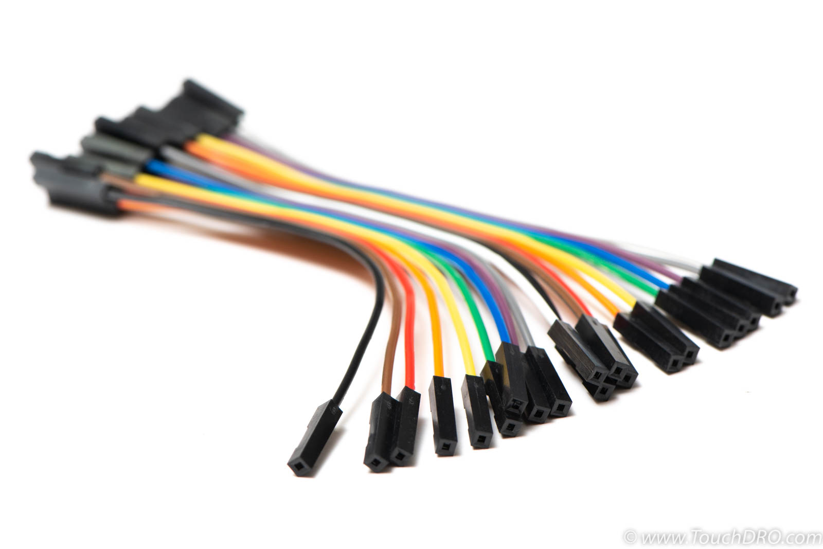
DuPont jumper wires are connecting wires with pre-crimped 1-pin male or female connectors on both ends. They are commonly used in breadboard prototyping but make good enough connection for a permanent DRO setup as well. Since MSP430 Launchpad comes with pre-installed male pin headers and so do most JY-MCU/HC-05 modules, female-to-female jumper wires provide an easy and flexible way to connect the two.
Many JY-MCU/HC-05 modules include a small ribbon cable, but if yours doesn't ,you can purchase 20-piece bundle of DuPont jumper wires in 5-10cm length for $2-$3.
Required Tools and Supplies
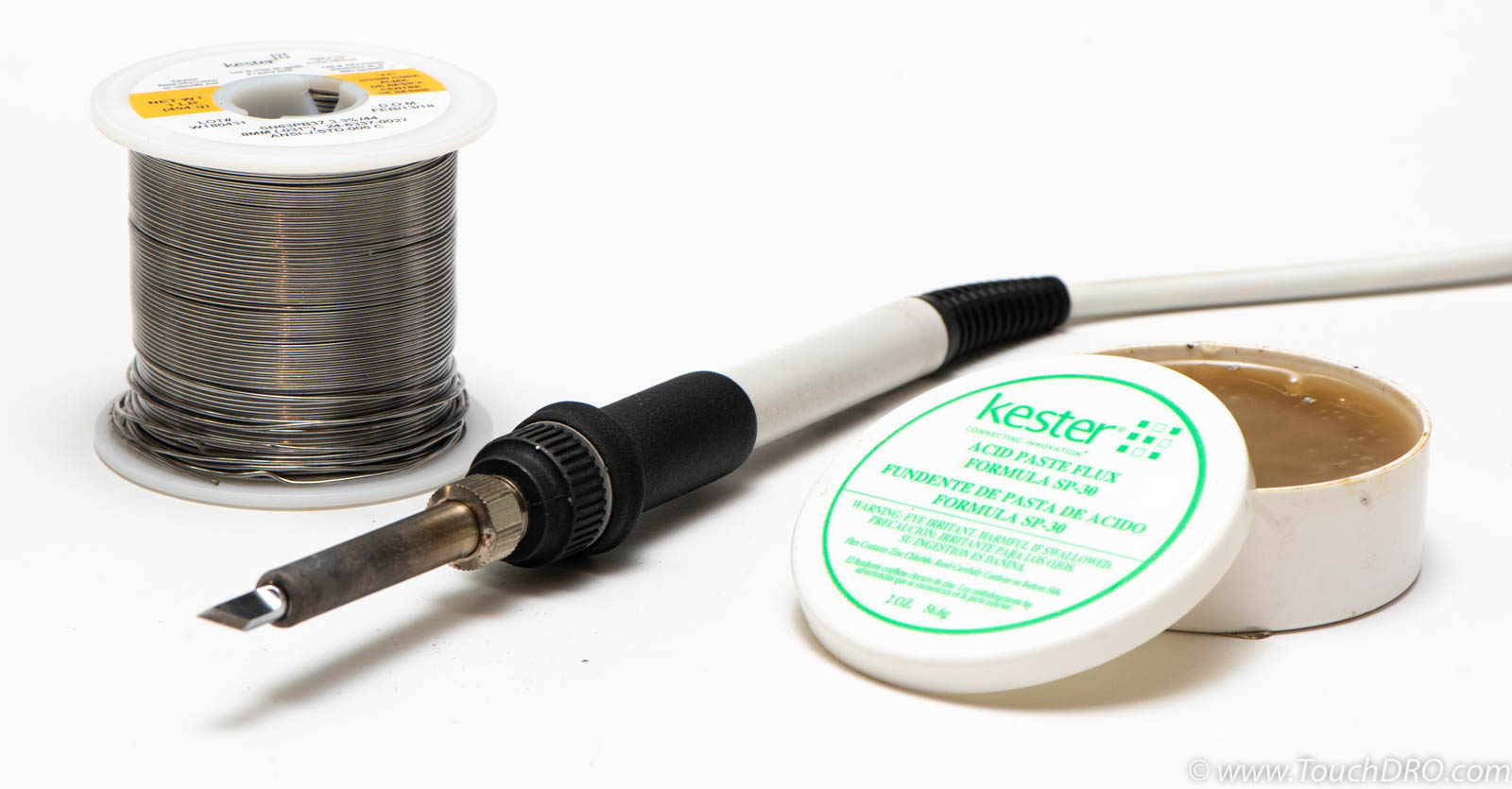
Soldering Iron
Since there is some soldering involved in building this adapter, you will need a soldering iron and some soldering supplies. The iron doesn't need to be particularly powerful or fancy since you will be making only a few connections but having a fine point would be a plus.
Solder
You will need a small amount of solder wire, preferably of Sn63/Pb37 or Sn60/Pb40 variety with rosin (or no-clean) flux core. Please don't use the solder that is not intended for electronic assembly.
Flux
Solder wire usually contains flux core but adding some paste flux to the solder joints will make soldering easier and the joints will be more solid. For this build you will need a small amount of paste flux. Rosin paste works best and is least corrosive when left on the board, but any kind of no-clean paste would work.
Hot Glue Gun and Glue
You will be connecting HC-05 [and possibly other component] to the Launchpad using jumper wires. The connection these wires make is generally secure enough but as an extra precaution it's not a bad idea to add a dab of hot glue to each connector. If you decide to glue the connectors, do it after the adapter is fully tested, though.
Build Instructions
Step 1: Flash the Firmware
Before going any further, ensure that the Launchpad is functional and the microcontroller can be successfully programmed.
Start by downloading and flashing the TouchDRO firmware into the microcontroller. Download links for the latest version of the firmware are located on the Download page along with links to pages that will help you select the correct version. Follow the instruction on the Flashing MSP430 Microcontroller page if you are not familiar with the flashing process.
Once the firmware is successfully flashed, power the launchpad from a phone charger or a battery bank and observe the status LEDs. If the microcontroller is working correctly, the "heartbeat" LED will blink once-per-second after the initial initialization routine.
Step 2: Connect The HC-05 Module
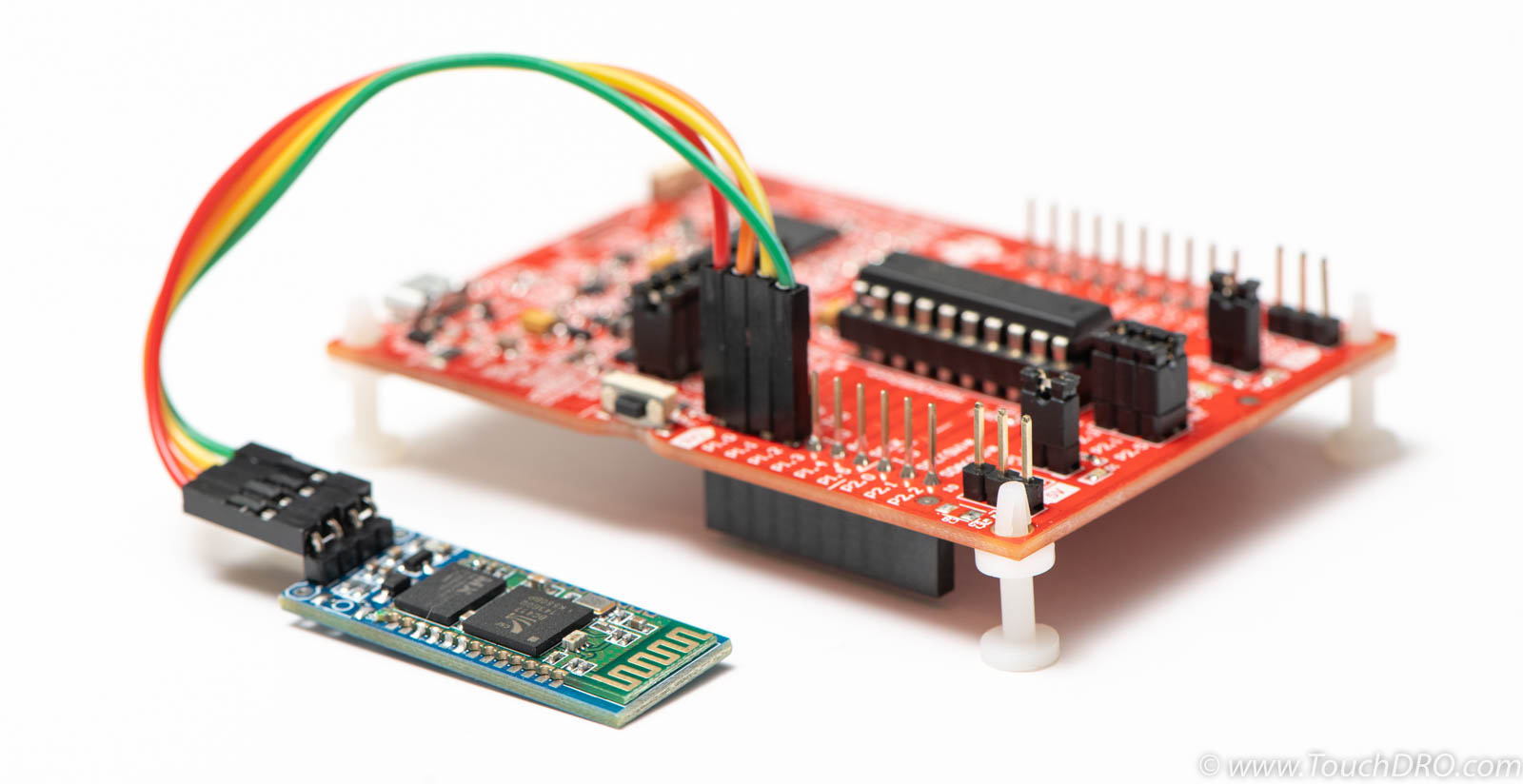
Now that you have confirmed that the Launchpad is in good working order, it's time to connect the HC-05 module to the board. If the module didn't come with pre-soldered 4-pin connector, add it now, so the end result looks similar to the picture below.

Use 4 DuPont jumper wires to connect the BlueTooth module to the Launchpad as shown below. The idea is to connect Vcc and Ground lines of the two devices and then connect Tx line to Rx line and vice versa. Note that Rx goes to Tx, not Rx to Rx, Tx to Tx.
Step 3: Test the Control Circuit
With the BlueTooth module connected and MSP430 microcontroller flashed, the basic control circuit is complete. At this point, it's a good idea to test the setup. This will ensure that the circuit is working correctly and can communicate with the tablet:
- Power up the circuit
- Ensure that the microcontroller status LED is still working as expected
- Ensure that the LED on the HC-05 modules is blinking
- Pair the adapter to the tablet
- Start TouchDRO application
- Connect to the adapter
- Wait for the app to display the "connected" status
- Wait for 30 seconds
- Ensure that the app is still connected and displays all 0s
Troubleshooting
Unless one of the parts you have is damaged or defective, there aren't many things that can go wrong at this point. If you run into any issues while flashing the firmware, the Flashing MSP430 Microcontroller page has useful troubleshooting information. For other issues refer to the Hardware Troubleshooting page.
Summary
Building the base TouchDRO adapter control circuit is very straight forward when using Value Line MSP430 Launchpad development kit. Following the instructions on this page, you should end up with a working TouchDRO adapter base circuit that can communicate with the application via it's BlueTooth module. Support for various DRO scales and encoders can be added by including the appropriate input stage circuit and possibly a secondary voltage regulator.