DIY DRO for iGaging and Shahe Scales
This is a DIY DRO adapter design that uses the 32-bit ESP32 DevKitC module to send data from DRO scales to the TouchDRO application. The DRO can decode data from up to four iGaging 21-bit scales, iGaging absolute scales, and Shahe BIN6 scales. The circuit is easy to build, and offers excellent performance and stability thanks to the advanced firmware, optimized to reduce noise and errors that are common with iGaging scales.
Circuit Overview
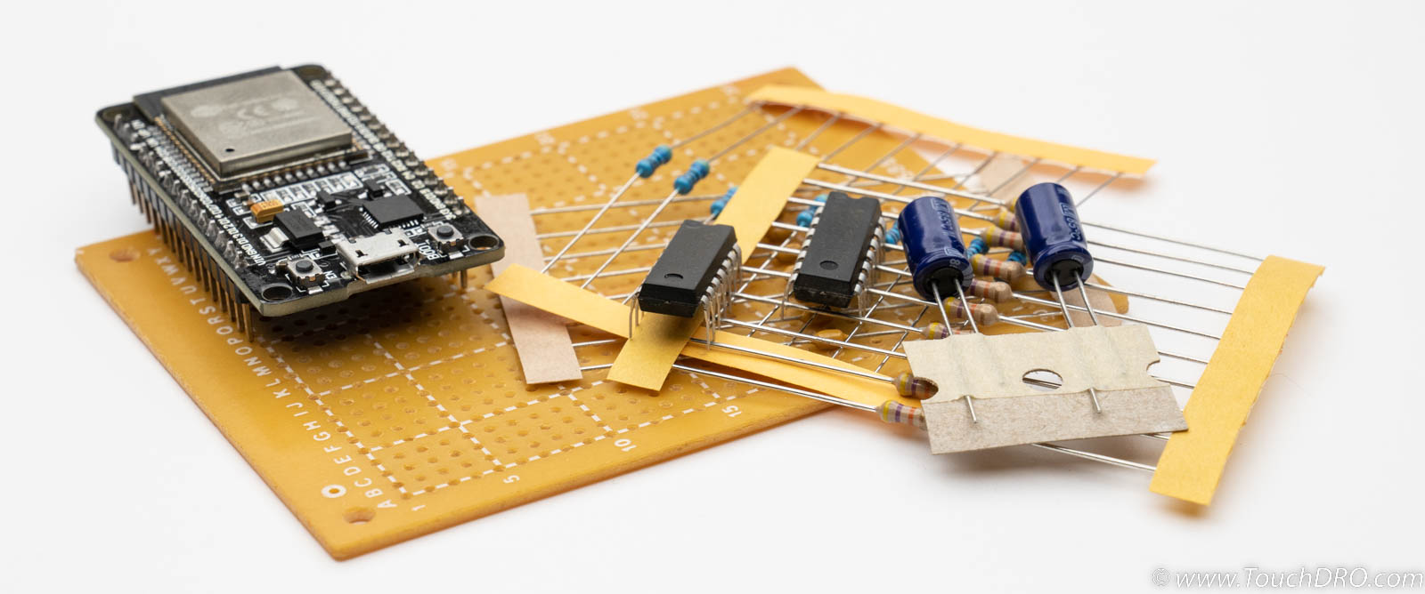
At the core of this adapter is the ESP32 DevKit C 32E development board. It is a self-contained circuit that includes the ESP32 WROOM module, USB-to-Serial interface, voltage regulator, and status LEDs. ESP32 WROOM has two powerful processors, hardware quadrature decoders, hardware tachometer, and built-in BlueTooth transceiver. Moreover, it's very inexpensive and readily available in most parts of the world. As a result, it makes a great platform for a DIY DRO.
The ESP32 module has one notable downside - it's not designed to be directly interfaced with the outside world, so its input pins don't have built-in Schmitt triggers. In order to safely connect scales to the module, the circuit for this DIY adapter uses two 74HC14 hex inverting Schmitt triggers. This to provides a robust and noise resistant input signal conditioning. Each scale input line has a series 4.7KOhm resistor and a NOT gate with a Schmitt trigger. The line is pulled up to the scales Vcc by a 47KOhm resistor.
The series resistor is necessary to protect the IC from overvoltage. Since 74HC14 is powered from 3.3V supply (so its output high signal is 3.3V).The 4.7K resistor will limit the current to a level that can safely be handled by the chip's internal diodes.
Additionally, each scale input has a 0.1uF bypass capacitors. Those are necessary to reduce noise on the scale's power supply line. The capacitors should be installed as close to the scale inputs as possible. Similarly, next to each of the 74HC14 there is a 0.1uF bypass capacitor.
Circuit Schematic
")
Bill Of Materials
| Value | Description | Qty. | Reference |
|---|---|---|---|
| ESP32 DevkitC-32E | ESP32 WROOM Dev. Kit | 1 | U1 |
| 74xx14 | SN74HC14N Hex Schmitt Trigger | 2 | IC1, IC2 |
| Capacitor, 0.1uF | Cap. ceramic, 0.1uF 50V | 8 | C1, C3, C5, C7, C11, C12 |
| Resistor, 4.7 KOhm | Metal film resistor, 4.7 KOhm, 1/4W, 5% | 10 | R1-10 |
| Resistor 47KOhm | Metal film resistor, 47 KOhm, 1/4W, 5% | 10 | R21-R30 |
Scale Input Configuration
For each input you will need to connect the Vcc pin to the 3.3V supply rail. If you follow the schematic, this will also connect the pull-up resistors to the same rail (this is very important; If you accidentally connect the resistors to 5V rail, you will permanently damage your scales). Additionally, iGaging 21-bit scales need to have the "CLOCK OUT" pin connected (R11-R14 on the schematic are simple wire jumpers).
DRO Firmware
For the ESP32 module to do anythig useful, you will need to download and flash (install) the TouchDRO firmware from the table below.
| Version | Description | Release Date | Files |
|---|---|---|---|
| 1.6 - Current | Fixed timing for iGaging EZ-View Rev. 1.7B Updated negative bit for Shahe scales |
Mar 12, 2023 | zip |
| 1.4 | Initial release for ESP32 DIY adapter | Oct 31, 2022 | zip |
To flash it into the ESP32 module you will need to install Espressif tool chain callend IDF. The process is more involved that upliading a sketch to an Arduino and requires installation of USB drivers and a few command line tools.The documentation is provide on the Espressif site.
To verify that the Espressif IDF is installed correctly, run the following command: esptool.py version
Your result should look similar to this:

Once you have a working environment, decompress the downloaded firmware into a folder and in the command line execute the following:
            esptool.py \
            -p /dev/ttyACM0 \
            -b 460800 \
            --before default_reset \
            --after hard_reset \
            --chip esp32  write_flash \
            --flash_mode dio \
            --flash_size detect \
            --flash_freq 40m \
            0x1000 bootloader.bin \
            0x8000 partition-table.bin \
            0x10000 touchdro-universal-32-v14.bin
Depending on your OS, the parameters will likely vary. Specifically, the -p parameter that specifies the port.
- On a UNIX/Linux based OS you can run 'ls /dev/TTy*' to see all TTY devices before you connect ESP32 to the USB port, and then run the same command after and find the difference (which will be the port for ESP32). In most cases it will be "TTy………."
- On Windows you can find the port used by ESP32 in the "Serial Ports" section of the device manager.
Build Tips and Testing
The build process for this adapter has two challenges:
- Flashing the firmware on ESP32 is a complicated process
- The input circuit requires a number of point-to-point connections
To simplify the testing you might want to break it into those two stages and test each stage individually.
ESP32 Firmware
ESP32 is a self contained module, and will run TouchDRO firmware just fine without the support circuitry. As such, your first step should be flashing the firmware onto the module and making sure that it works as expected:
- Power up the module from USB and confirm that red LED is lit and blue LED is blinking
- Pair the module with your Android tablet and make sure the pairing process succeeds. Device name in the BT device list should be "TouchDRO DIY"
- Open TouchDRO application and connect it to the module
- Leave TouchDRO running for at least a minute. The application should not lose the connection
Optionally, you can install a BlueTooth terminal application (such as BlueTerm) and do the following:
- Disconnect TouchDRO application (if connected)
- Connect to the DRO adapter via BlueTerm
- You should see a data stream that contains x0;y0;z0;w0;t0;p0;
- Find the probe pin (see pinout above) and short it to the ground
- The value for p in the data stream should change to p1; and the stream should speed up
- Disconnect the pin from the ground; p should return to p0;
If the tests pass, the firmware is running as expected.
Input Circuit
Once you build the input circuit (before connecting anything to the ESP32 module), it's a good idea to test each line to make sure the connections are working. For this, you can do the following:
- Connect 5V, 3.3V and Ground to the ESP32 module (see pinout above). Alternatively, you can use a bench power supply or even batteries.
- Using a Voltmeter, check voltage at each input pin. Since the pins are pulled up to Vcc, the voltage should be very close to nominal Vcc (5V or 3.3V, depending on your configuration)
- Using a Voltmeter, check the voltage at each output (the line that will be connected to ESP32). The voltage should be close to 0V, since 74HC14 is an inverting Schmitt trigger.
- Ground each input line and check the voltage at the output. It should be close to 3.3V
If all these tests pass, your circuit is working as expected and you can now connect it to the ESP32 module. Otherwise, re-check your connection, fix any problems and retest again.
Scale Wiring
To find out the wiring for your scales, refer to the Overview of Capacitive DRO Scales and follow the link to your particular scale model.
Mid-way on the page with the scale details there will be table(s) with the pinouts. Connect Vcc, Ground, Data, and Clock pins to the appropriate inputs on the adapter.
If you're using iGaging EZ-View scales, make sure to connect the "clock out" lines. Other scales don't need them.
Note that the bypass capacitors are very important, since these scales are very prone to noise and glitches. Ideally, these capacitors should be installed inside the scale's reading head. If you are not comfortable modifying the reading head, the capacitors should be installed on the USB breakout boards [unless you are planning to hard-wire the scales to the main PCB].